Hardware Maintenance Manual
Page 3
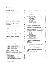
...CMV, and GAV 28 Product definition 28 FRU identification for replacing a system board 28 How to do first 31 Checkout guide 32 Lenovo Solution Center 32 Quick test programs 32 UEFI diagnostic program 33 Bootable diagnostic programs 33 Power system checkout 34 Checking the ac power ... computer 64 1010 Battery pack 64 1020 Bottom door 65 1030 Optical drive 66 1040 Hard disk drive or solid-state drive assembly 68 1050 Keyboard 69 1060 Memory module 72 i Safety information 1 General safety 1 Electrical safety 2 Safety inspection guide 3 Handling devices that are sensitive to ...
...CMV, and GAV 28 Product definition 28 FRU identification for replacing a system board 28 How to do first 31 Checkout guide 32 Lenovo Solution Center 32 Quick test programs 32 UEFI diagnostic program 33 Bootable diagnostic programs 33 Power system checkout 34 Checking the ac power ... computer 64 1010 Battery pack 64 1020 Bottom door 65 1030 Optical drive 66 1040 Hard disk drive or solid-state drive assembly 68 1050 Keyboard 69 1060 Memory module 72 i Safety information 1 General safety 1 Electrical safety 2 Safety inspection guide 3 Handling devices that are sensitive to ...

Hardware Maintenance Manual
Page 4
... Card for wireless WAN or mSATA solid-state drive 73 1080 PCI Express Mini Card for wireless LAN/WiMAX 79 1090 Backup battery 81 1100 Keyboard bezel 82 1110 ExpressCard reader board or ExpressCard dummy card 85 1120 Bluetooth daughter card 87 1130 I/O sub card 88 1140 Speaker assembly 89 1150...
... Card for wireless WAN or mSATA solid-state drive 73 1080 PCI Express Mini Card for wireless LAN/WiMAX 79 1090 Backup battery 81 1100 Keyboard bezel 82 1110 ExpressCard reader board or ExpressCard dummy card 85 1120 Bluetooth daughter card 87 1130 I/O sub card 88 1140 Speaker assembly 89 1150...
Hardware Maintenance Manual
Page 38
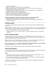
... from the Lenovo Support Web... information, along with the ThinkPad notebook computers. • ... been dropped. Lenovo Solution Center The Lenovo Solution Center program...lenovo.com/diagnose. It ...Lenovo Solution Center, click Start ➙ Control Panel ➙ System and Security ➙ Lenovo...Lenovo Solution Center program is not installed with the Lenovo Solution Center program, you are applicable to http://www.lenovo... Lenovo Hard Drive Quick Test and Lenovo ... or use of non-ThinkPad products, prototype cards,...been subjected to test only ThinkPad products. The use of ...
... from the Lenovo Support Web... information, along with the ThinkPad notebook computers. • ... been dropped. Lenovo Solution Center The Lenovo Solution Center program...lenovo.com/diagnose. It ...Lenovo Solution Center, click Start ➙ Control Panel ➙ System and Security ➙ Lenovo...Lenovo Solution Center program is not installed with the Lenovo Solution Center program, you are applicable to http://www.lenovo... Lenovo Hard Drive Quick Test and Lenovo ... or use of non-ThinkPad products, prototype cards,...been subjected to test only ThinkPad products. The use of ...
Hardware Maintenance Manual
Page 46
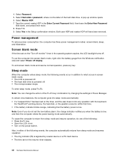
...: • The ring indicator (RI) is powered off display. Press F10. 9. To end screen blank mode and resume normal operation, press any operation with the keyboard, the TrackPoint® pointing device, the hard disk, or the parallel connector within that time. • If the battery indicator blinks orange, indicating that the...
...: • The ring indicator (RI) is powered off display. Press F10. 9. To end screen blank mode and resume normal operation, press any operation with the keyboard, the TrackPoint® pointing device, the hard disk, or the parallel connector within that time. • If the battery indicator blinks orange, indicating that the...

Hardware Maintenance Manual
Page 47
... 44 • "Undetermined problems" on page 44 The symptom-to restart the system. In the displays, n can also help you do any operation with the keyboard, the TrackPoint pointing device, the hard disk drive, or the parallel connector within that causes the system to go into hibernation mode, use the Power...
... 44 • "Undetermined problems" on page 44 The symptom-to restart the system. In the displays, n can also help you do any operation with the keyboard, the TrackPoint pointing device, the hard disk drive, or the parallel connector within that causes the system to go into hibernation mode, use the Power...
Hardware Maintenance Manual
Page 55
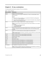
... the combination to put the computer into sleep mode. Fn key combinations The following device drivers must install the ThinkPad Power Management Driver on a conventional keyboard. Press Fn+F5 to open the Communications settings window. Wireless device drivers Press Fn+F6 to enable or disable...display becomes dimmer. Has the same function as the Pause key on ThinkPad L430 and L530 models. © Copyright Lenovo 2012 49 To return to lock the computer. Fn+Spacebar is not supported on a conventional keyboard. Fn+F4 Press Fn+F4 to put the computer into hibernation ...
... the combination to put the computer into sleep mode. Fn key combinations The following device drivers must install the ThinkPad Power Management Driver on a conventional keyboard. Press Fn+F5 to open the Communications settings window. Wireless device drivers Press Fn+F6 to enable or disable...display becomes dimmer. Has the same function as the Pause key on ThinkPad L430 and L530 models. © Copyright Lenovo 2012 49 To return to lock the computer. Fn+Spacebar is not supported on a conventional keyboard. Fn+F4 Press Fn+F4 to put the computer into hibernation ...

Hardware Maintenance Manual
Page 59
... http://www.lenovo.com/support. CRU information and replacement instructions are concealed by an access panel that a Service Provider install the CRU according to find a list of this Hardware Maintenance Manual. See your product. Chapter 7. ThinkPad computers contain the following types of the replacement..., and hard disk drive. You might include the memory module, wireless card, keyboard, and palm rest with the replacement CRU; Other self-service CRUs depending on installing the CRU, Lenovo will be found at any time upon request. Examples of these types of self...
... http://www.lenovo.com/support. CRU information and replacement instructions are concealed by an access panel that a Service Provider install the CRU according to find a list of this Hardware Maintenance Manual. See your product. Chapter 7. ThinkPad computers contain the following types of the replacement..., and hard disk drive. You might include the memory module, wireless card, keyboard, and palm rest with the replacement CRU; Other self-service CRUs depending on installing the CRU, Lenovo will be found at any time upon request. Examples of these types of self...

Hardware Maintenance Manual
Page 60
Major FRUs and CRUs 1 27 26 2 3 25 4 24 23 5 22 6 21 7 20 19 8 18 9 10 11 17 12 16 15 13 14 No. Description Self-service CRU Optional-service CRU 1 LCD unit No No 2 PCI Express Mini Card for wireless LAN/WiMAX No Yes 3 Memory module (under the keyboard) No Yes 4 Keyboard bezel No No 5 DC-in cable No No 6 RJ45 sub card and Always On USB connector board No No 7 Microprocessor No No 54 Hardware Maintenance Manual
Major FRUs and CRUs 1 27 26 2 3 25 4 24 23 5 22 6 21 7 20 19 8 18 9 10 11 17 12 16 15 13 14 No. Description Self-service CRU Optional-service CRU 1 LCD unit No No 2 PCI Express Mini Card for wireless LAN/WiMAX No Yes 3 Memory module (under the keyboard) No Yes 4 Keyboard bezel No No 5 DC-in cable No No 6 RJ45 sub card and Always On USB connector board No No 7 Microprocessor No No 54 Hardware Maintenance Manual

Hardware Maintenance Manual
Page 61
... some models) No No 23 ExpressCard reader board (on some models) No No 24 Thermal fan assembly No No 25 Backup battery No Yes 26 Keyboard No Yes 27 Trackpoint cap Yes No Chapter 7. Locations 55 No.
... some models) No No 23 ExpressCard reader board (on some models) No No 24 Thermal fan assembly No No 25 Backup battery No Yes 26 Keyboard No Yes 27 Trackpoint cap Yes No Chapter 7. Locations 55 No.

Hardware Maintenance Manual
Page 75
Removing or replacing a FRU 69 Removal steps of hard disk drive or solid-state drive bracket 1 1 1 1 Step 1 Screw (quantity) M3 × 2.8 mm, flat-head (4) Color Silver Torque 0.392 Nm (4.00 kgfcm) 2 1050 Keyboard For access, remove these FRUs in order: • "1010 Battery pack" on page 64 • "1020 Bottom door" on page 65 Chapter 9.
Removing or replacing a FRU 69 Removal steps of hard disk drive or solid-state drive bracket 1 1 1 1 Step 1 Screw (quantity) M3 × 2.8 mm, flat-head (4) Color Silver Torque 0.392 Nm (4.00 kgfcm) 2 1050 Keyboard For access, remove these FRUs in order: • "1010 Battery pack" on page 64 • "1020 Bottom door" on page 65 Chapter 9.

Hardware Maintenance Manual
Page 76
Step 1 Screw (quantity) M2 × 14 mm, flat-head, nylon-coated (2) Color Black Torque 0.181 Nm (1.85 kgfcm) Press the keyboard as shown in the following illustration until the hooks on the rear edge of keyboard 1 1 When installing: Ensure that the screws are detached from the keyboard bezel. 2 2 Lift the keyboard up 3 , and then detach the keyboard connectors 4 . 70 Hardware Maintenance Manual Removal steps of the keyboard are fastened and the keyboard is secured.
Step 1 Screw (quantity) M2 × 14 mm, flat-head, nylon-coated (2) Color Black Torque 0.181 Nm (1.85 kgfcm) Press the keyboard as shown in the following illustration until the hooks on the rear edge of keyboard 1 1 When installing: Ensure that the screws are detached from the keyboard bezel. 2 2 Lift the keyboard up 3 , and then detach the keyboard connectors 4 . 70 Hardware Maintenance Manual Removal steps of the keyboard are fastened and the keyboard is secured.

Hardware Maintenance Manual
Page 77
When the front side of the keyboard are attached firmly to slide the keyboard toward you until it snaps into position. Removing or replacing a FRU 71 3 4 When installing: Ensure that the hooks on the front edge of the keyboard is housed firmly, gently press the keys with your palms to the system board. When installing: Ensure that all the connectors are under the frame as shown in the following illustration. Chapter 9.
When the front side of the keyboard are attached firmly to slide the keyboard toward you until it snaps into position. Removing or replacing a FRU 71 3 4 When installing: Ensure that the hooks on the front edge of the keyboard is housed firmly, gently press the keys with your palms to the system board. When installing: Ensure that all the connectors are under the frame as shown in the following illustration. Chapter 9.
Hardware Maintenance Manual
Page 78
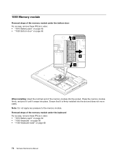
... firmly installed into place. 1060 Memory module Removal steps of the memory module under the keyboard For access, remove these FRUs in order: • "1010 Battery pack" on page 64 • "1050 Keyboard" on page 69 • "1100 Keyboard bezel" on page 65 1 2 1 When installing: Insert the notched end of the memory module...
... firmly installed into place. 1060 Memory module Removal steps of the memory module under the keyboard For access, remove these FRUs in order: • "1010 Battery pack" on page 64 • "1050 Keyboard" on page 69 • "1100 Keyboard bezel" on page 65 1 2 1 When installing: Insert the notched end of the memory module...

Hardware Maintenance Manual
Page 79
... module firmly, and pivot it until it is to be installed on the computer you are servicing, install it in the slot located under the keyboard. If only one memory module is firmly installed into the slot and does not move easily. Ensure that it snaps into the socket. 1 2 1 When installing... door" on page 65 Depending on model, the computer you are servicing might come with one under the bottom door and the other under the keyboard. 1070 PCI Express Mini Card for wireless WAN, or mSATA solid-state drive.
... module firmly, and pivot it until it is to be installed on the computer you are servicing, install it in the slot located under the keyboard. If only one memory module is firmly installed into the slot and does not move easily. Ensure that it snaps into the socket. 1 2 1 When installing... door" on page 65 Depending on model, the computer you are servicing might come with one under the bottom door and the other under the keyboard. 1070 PCI Express Mini Card for wireless WAN, or mSATA solid-state drive.

Hardware Maintenance Manual
Page 85
2 1080 PCI Express Mini Card for wireless LAN/WiMAX For access, remove these FRUs in order: • "1010 Battery pack" on page 64 • "1050 Keyboard" on page 69 Chapter 9. Removing or replacing a FRU 79
2 1080 PCI Express Mini Card for wireless LAN/WiMAX For access, remove these FRUs in order: • "1010 Battery pack" on page 64 • "1050 Keyboard" on page 69 Chapter 9. Removing or replacing a FRU 79

Hardware Maintenance Manual
Page 87
Chapter 9. Any other battery could ignite or explode. Removing or replacing a FRU 81 3 Note: WiMAX is supported on L530 models for Japan only. 1090 Backup battery For access, remove these FRUs in order: • "1010 Battery pack" on page 64 • "1050 Keyboard" on page 69 Removal steps of backup battery DANGER Use only the authorized battery specified for your computer.
Chapter 9. Any other battery could ignite or explode. Removing or replacing a FRU 81 3 Note: WiMAX is supported on L530 models for Japan only. 1090 Backup battery For access, remove these FRUs in order: • "1010 Battery pack" on page 64 • "1050 Keyboard" on page 69 Removal steps of backup battery DANGER Use only the authorized battery specified for your computer.

Hardware Maintenance Manual
Page 88
2 1 When installing: Ensure that the battery connector is attached firmly to the system board. 1100 Keyboard bezel For access, remove these FRUs in order: • "1010 Battery pack" on page 64 • "1020 Bottom door" on page 65 • "1030 Optical drive" on page 66 • "1040 Hard disk drive or solid-state drive assembly" on page 68 • "1050 Keyboard" on page 69 82 Hardware Maintenance Manual
2 1 When installing: Ensure that the battery connector is attached firmly to the system board. 1100 Keyboard bezel For access, remove these FRUs in order: • "1010 Battery pack" on page 64 • "1020 Bottom door" on page 65 • "1030 Optical drive" on page 66 • "1040 Hard disk drive or solid-state drive assembly" on page 68 • "1050 Keyboard" on page 69 82 Hardware Maintenance Manual

Hardware Maintenance Manual
Page 89
Removal steps of keyboard bezel 2 1 21 1 1 2 2 2 2 22 2 1 1 Step 1 2 Screw (quantity) M2 × 5 mm, flat-head, nylon-coated (6) M2 × 3 mm, flat-head, nylon-coated (9) Color Black Black Torque 0.392 Nm (4 kgfcm) 0.181 Nm (1.85 kgfcm) 3 3 3 Step 3 Screw (quantity) M2 × 8 mm, flat-head, nylon-coated (3) Color Black Torque 0.181 Nm (1.85 kgfcm) Chapter 9. Removing or replacing a FRU 83
Removal steps of keyboard bezel 2 1 21 1 1 2 2 2 2 22 2 1 1 Step 1 2 Screw (quantity) M2 × 5 mm, flat-head, nylon-coated (6) M2 × 3 mm, flat-head, nylon-coated (9) Color Black Black Torque 0.392 Nm (4 kgfcm) 0.181 Nm (1.85 kgfcm) 3 3 3 Step 3 Screw (quantity) M2 × 8 mm, flat-head, nylon-coated (3) Color Black Torque 0.181 Nm (1.85 kgfcm) Chapter 9. Removing or replacing a FRU 83
Hardware Maintenance Manual
Page 91
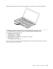
Release the keyboard bezel from the frame using a plastic pry tool as shown in the following illustration. 10 1110 ExpressCard reader board or ExpressCard dummy card For access, ... • "1030 Optical drive" on page 66 • "1040 Hard disk drive or solid-state drive assembly" on page 68 • "1050 Keyboard" on page 69 • "1100 Keyboard bezel" on page 82 If the computer you are servicing supports the ExpressCard, follow the following instructions to remove or replace the ExpressCard...
Release the keyboard bezel from the frame using a plastic pry tool as shown in the following illustration. 10 1110 ExpressCard reader board or ExpressCard dummy card For access, ... • "1030 Optical drive" on page 66 • "1040 Hard disk drive or solid-state drive assembly" on page 68 • "1050 Keyboard" on page 69 • "1100 Keyboard bezel" on page 82 If the computer you are servicing supports the ExpressCard, follow the following instructions to remove or replace the ExpressCard...
Hardware Maintenance Manual
Page 94
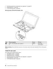
• "1040 Hard disk drive or solid-state drive assembly" on page 68 • "1050 Keyboard" on page 69 • "1100 Keyboard bezel" on page 82 Removal steps of bluetooth daughter card 1 2 Step 1 Screw (quantity) M2 × 3 mm, flat-head, nylon-coated (1) Color Black Torque 0.181 Nm (1...." on page 65 • "1030 Optical drive" on page 66 • "1040 Hard disk drive or solid-state drive assembly" on page 68 • "1050 Keyboard" on page 69 • "1100 Keyboard bezel" on page 82 88 Hardware Maintenance Manual
• "1040 Hard disk drive or solid-state drive assembly" on page 68 • "1050 Keyboard" on page 69 • "1100 Keyboard bezel" on page 82 Removal steps of bluetooth daughter card 1 2 Step 1 Screw (quantity) M2 × 3 mm, flat-head, nylon-coated (1) Color Black Torque 0.181 Nm (1...." on page 65 • "1030 Optical drive" on page 66 • "1040 Hard disk drive or solid-state drive assembly" on page 68 • "1050 Keyboard" on page 69 • "1100 Keyboard bezel" on page 82 88 Hardware Maintenance Manual


