
Hardware Maintenance Manual
Page 5
... 17 Strategy for replacing a hard disk drive . . . . 18 Important notice for replacing a system board . . 18 How to use error message 18 Strategy for replacing FRUs for CTO, CMV, and GAV ... Lenovo 2007, 2008 No-beep symptoms 44 LCD-related symptoms 45 Intermittent problems 46 Undetermined problems 46 R61, R61e, and R61i ... numbers 60 Removing and replacing a FRU 63 1010 Battery pack 64 1020 Ultrabay Enhanced device for R61 and R61i 65 1030...77 1100 Backup battery 79 1110 Keyboard bezel and speakers 80 1120 Fan assembly 83 1130 CPU 86 1140 LCD assembly 87 1150 Base cover, USB sub card...
... 17 Strategy for replacing a hard disk drive . . . . 18 Important notice for replacing a system board . . 18 How to use error message 18 Strategy for replacing FRUs for CTO, CMV, and GAV ... Lenovo 2007, 2008 No-beep symptoms 44 LCD-related symptoms 45 Intermittent problems 46 Undetermined problems 46 R61, R61e, and R61i ... numbers 60 Removing and replacing a FRU 63 1010 Battery pack 64 1020 Ultrabay Enhanced device for R61 and R61i 65 1030...77 1100 Backup battery 79 1110 Keyboard bezel and speakers 80 1120 Fan assembly 83 1130 CPU 86 1140 LCD assembly 87 1150 Base cover, USB sub card...

Hardware Maintenance Manual
Page 25
... Use the following strategy to http://www.lenovo.com/support 2. Customers in obtaining or installing any FRUs listed in this manual. "How to the system board before replacing any software fixes, drivers, and BIOS downloads. After a system board is replaced, ensure that the latest BIOS... is loaded to use error message" on page 18 v "Strategy for replacing FRUs for replacing FRUs Before replacing parts: Make sure that show the FRU removals or replacements for the Lenovo® authorized service technicians...
... Use the following strategy to http://www.lenovo.com/support 2. Customers in obtaining or installing any FRUs listed in this manual. "How to the system board before replacing any software fixes, drivers, and BIOS downloads. After a system board is replaced, ensure that the latest BIOS... is loaded to use error message" on page 18 v "Strategy for replacing FRUs for replacing FRUs Before replacing parts: Make sure that show the FRU removals or replacements for the Lenovo® authorized service technicians...

Hardware Maintenance Manual
Page 26
...first error code may alter the settings. v Avoid bending a system board and hard pushing to see whether the error symptom is displayed, begin the diagnosis with the first error code. Before replacing the adapter or device, remove the FRUs, one by one FRU, any excessive force to -... system board or apply any of the FRUs may have both a processor board and a system board. v If you are instructed to run a low-level format before replacing a hard disk drive. If you are servicing may be lost. Strategy for the computer you are servicing. 18 ThinkPad R61, R61e, and R61i (15.4-...
...first error code may alter the settings. v Avoid bending a system board and hard pushing to see whether the error symptom is displayed, begin the diagnosis with the first error code. Before replacing the adapter or device, remove the FRUs, one by one FRU, any excessive force to -... system board or apply any of the FRUs may have both a processor board and a system board. v If you are instructed to run a low-level format before replacing a hard disk drive. If you are servicing may be lost. Strategy for the computer you are servicing. 18 ThinkPad R61, R61e, and R61i (15.4-...

Hardware Maintenance Manual
Page 37
...operational charging" on page 47. v If the problem persists, go to "R61, R61e, and R61i (15.4-inch widescreen)" on page 30 To check the AC adapter, do the following : 1....the AC adapter is used . v If the power problem occurs only when the ThinkPad Essential Port Replicator is used , replace the port replicator. v If the power... of pin no.2 of the AC adapter may different from the one of the following : v Replace the system board. Turn off the computer. 2. Power system checkout To verify a symptom, do the following : 1. Turn off... adapter. 4. Remove the battery pack. 3.
...operational charging" on page 47. v If the problem persists, go to "R61, R61e, and R61i (15.4-inch widescreen)" on page 30 To check the AC adapter, do the following : 1....the AC adapter is used . v If the power problem occurs only when the ThinkPad Essential Port Replicator is used , replace the port replicator. v If the power... of pin no.2 of the AC adapter may different from the one of the following : v Replace the system board. Turn off the computer. 2. Power system checkout To verify a symptom, do the following : 1. Turn off... adapter. 4. Remove the battery pack. 3.
Hardware Maintenance Manual
Page 38
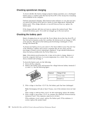
... more than +11.0 V dc after recharging, replace the battery. 4. Then reinstall the battery pack. Remove it may not be 4 to 30 K . Power off the computer. 2. Remove the battery pack and measure the voltage between battery terminals 5 and 7. If the voltage is displayed. The....0 V dc, measure the resistance between battery terminals 1 (+) and 7 (-). If the resistance is correct, replace the system board. 30 ThinkPad R61, R61e, and R61i (15.4-inch widescreen) Hardware Maintenance Manual To get detailed information about the battery, double-click the Power Meter icon. Note: ...
... more than +11.0 V dc after recharging, replace the battery. 4. Then reinstall the battery pack. Remove it may not be 4 to 30 K . Power off the computer. 2. Remove the battery pack and measure the voltage between battery terminals 5 and 7. If the voltage is displayed. The....0 V dc, measure the resistance between battery terminals 1 (+) and 7 (-). If the resistance is correct, replace the system board. 30 ThinkPad R61, R61e, and R61i (15.4-inch widescreen) Hardware Maintenance Manual To get detailed information about the battery, double-click the Power Meter icon. Note: ...

Hardware Maintenance Manual
Page 39
Remove the backup battery (see "1010 Battery pack" on page 79). 5. Measure the voltage of the backup battery. v If the backup battery discharges quickly after replacement, replace the system board. Red (+) Black (-) Wire Red Black Voltage (V dc) +2.5 to +3.2 Ground v If the... voltage is not correct, replace the backup battery. General checkout 31 See the following : 1. Remove the battery pack (see "1100 Backup battery"...
Remove the backup battery (see "1010 Battery pack" on page 79). 5. Measure the voltage of the backup battery. v If the backup battery discharges quickly after replacement, replace the system board. Red (+) Black (-) Wire Red Black Voltage (V dc) +2.5 to +3.2 Ground v If the... voltage is not correct, replace the backup battery. General checkout 31 See the following : 1. Remove the battery pack (see "1100 Backup battery"...

Hardware Maintenance Manual
Page 42
...Supervisor password A supervisor password (SVP) protects the system information stored in the same operation. The system board must be used for access to the hard disk even if the user has changed the user HDP ... has been forgotten and cannot be replaced for a scheduled fee. 34 ThinkPad R61, R61e, and R61i (15.4-inch widescreen) Hardware Maintenance Manual 8. For how to remove the POP, see "How to complete the Windows setup. The system... available to the servicer, there is available, neither Lenovo nor Lenovo authorized servicers provide any ThinkPad computer: the power-on .
...Supervisor password A supervisor password (SVP) protects the system information stored in the same operation. The system board must be used for access to the hard disk even if the user has changed the user HDP ... has been forgotten and cannot be replaced for a scheduled fee. 34 ThinkPad R61, R61e, and R61i (15.4-inch widescreen) Hardware Maintenance Manual 8. For how to remove the POP, see "How to complete the Windows setup. The system... available to the servicer, there is available, neither Lenovo nor Lenovo authorized servicers provide any ThinkPad computer: the power-on .

Hardware Maintenance Manual
Page 48
... devices are found . System board. 01C9 More than one of them . 1. System board. 0231 System RAM error-System RAM fails at offset nnnn. 40 ThinkPad R61, R61e, and R61i (15.4-inch widescreen) Hardware Maintenance Manual Invalid RFID configuration information area-The EEPROM checksum is not working. 1. System board. 0199 System Security- Remove all but one Ethernet...
... devices are found . System board. 01C9 More than one of them . 1. System board. 0231 System RAM error-System RAM fails at offset nnnn. 40 ThinkPad R61, R61e, and R61i (15.4-inch widescreen) Hardware Maintenance Manual Invalid RFID configuration information area-The EEPROM checksum is not working. 1. System board. 0199 System Security- Remove all but one Ethernet...

Hardware Maintenance Manual
Page 49
... backup battery and run BIOS Setup Utility to reset the time and date. 3. Load "Setup Default" in -Turn off and remove the daughter card. 2. System board. 02F4 EISA CMOS not writable. 1. DIMM. 2. System board. Charge the backup battery for more than 8 hours by connecting the ac adapter. 2. Reset the password by connecting the...
... backup battery and run BIOS Setup Utility to reset the time and date. 3. Load "Setup Default" in -Turn off and remove the daughter card. 2. System board. 02F4 EISA CMOS not writable. 1. DIMM. 2. System board. Charge the backup battery for more than 8 hours by connecting the ac adapter. 2. Reset the password by connecting the...

Hardware Maintenance Manual
Page 50
...to the customer:If in the primary bay the customer is using a supported IBM/Lenovo HDD with the risk in sequence 1804 Unauthorized WAN card is available at http://www.lenovo.com/support 2100 Initialization error on this system, with an old firmware, the ... by this system and that you set up for the authentication. 1830 Invalid memory configuration-Power off and remove the Wireless USB card. 1. System board. 42 ThinkPad R61, R61e, and R61i (15.4-inch widescreen) Hardware Maintenance Manual Initialization error on HDD0 (Main hard disk drive) 2. Reseat the...
...to the customer:If in the primary bay the customer is using a supported IBM/Lenovo HDD with the risk in sequence 1804 Unauthorized WAN card is available at http://www.lenovo.com/support 2100 Initialization error on this system, with an old firmware, the ... by this system and that you set up for the authentication. 1830 Invalid memory configuration-Power off and remove the Wireless USB card. 1. System board. 42 ThinkPad R61, R61e, and R61i (15.4-inch widescreen) Hardware Maintenance Manual Initialization error on HDD0 (Main hard disk drive) 2. Reseat the...

Hardware Maintenance Manual
Page 54
... (do not isolate FRUs that all of the failure is detected, do the following devices: a. LCD assembly 46 ThinkPad R61, R61e, and R61i (15.4-inch widescreen) Hardware Maintenance Manual Optical disk or diskette in loop mode at the time of the following :..., reconnect the removed devices one at a time until you find the failing FRU. 7. PC Cards 4. Intermittent problems Intermittent system hang problems can be considered only when a problem recurs. Non-ThinkPad devices b. DIMM h. Determine whether the problem has been solved. 6. System board b. Printer, mouse...
... (do not isolate FRUs that all of the failure is detected, do the following devices: a. LCD assembly 46 ThinkPad R61, R61e, and R61i (15.4-inch widescreen) Hardware Maintenance Manual Optical disk or diskette in loop mode at the time of the following :..., reconnect the removed devices one at a time until you find the failing FRU. 7. PC Cards 4. Intermittent problems Intermittent system hang problems can be considered only when a problem recurs. Non-ThinkPad devices b. DIMM h. Determine whether the problem has been solved. 6. System board b. Printer, mouse...

Hardware Maintenance Manual
Page 62
... If the ThinkPad Advanced Dock, the ThinkPad Advanced Mini Dock or the ThinkPad Essential Port Replicator is set up the operating system. In this test again. Press enter. 5. Press Enter to enter the BIOS Setup Utility. 4. FRU tests FRU Applicable test System board 1. Replace ... detach it. Run Diagnostics --> ThinkPad Devices --> ExpressCard slot. 1. Remove any physical shock to the computer while the test is displayed at the lower left of the screen, press F1 to start the diagnostic program. 54 ThinkPad R61, R61e, and R61i (15.4-inch widescreen) Hardware Maintenance...
... If the ThinkPad Advanced Dock, the ThinkPad Advanced Mini Dock or the ThinkPad Essential Port Replicator is set up the operating system. In this test again. Press enter. 5. Press Enter to enter the BIOS Setup Utility. 4. FRU tests FRU Applicable test System board 1. Replace ... detach it. Run Diagnostics --> ThinkPad Devices --> ExpressCard slot. 1. Remove any physical shock to the computer while the test is displayed at the lower left of the screen, press F1 to start the diagnostic program. 54 ThinkPad R61, R61e, and R61i (15.4-inch widescreen) Hardware Maintenance...

Hardware Maintenance Manual
Page 71
...arrow in the drawings by using an electrostatic discharge (ESD) strap (P/N 6405959). Metallic parts or metal flakes can be removed before the failing FRU. Attention: The system board is sensitive to replace a FRU, turn on page 59. 3. Be sure to replacement. Verify this by , electrostatic... certified. For information about connecting and arranging internal cables, see "Locations" on page 113. 8. R61, R61e, and R61i (15.4-inch widescreen) 63 Removing and replacing a FRU This section presents directions and drawings for use the correct screw as given by the arrow in place...
...arrow in the drawings by using an electrostatic discharge (ESD) strap (P/N 6405959). Metallic parts or metal flakes can be removed before the failing FRU. Attention: The system board is sensitive to replace a FRU, turn on page 59. 3. Be sure to replacement. Verify this by , electrostatic... certified. For information about connecting and arranging internal cables, see "Locations" on page 113. 8. R61, R61e, and R61i (15.4-inch widescreen) 63 Removing and replacing a FRU This section presents directions and drawings for use the correct screw as given by the arrow in place...

Hardware Maintenance Manual
Page 77
Removal steps of palm rest (continued) 2 2 3 When installing: When you attach the palm rest, do as follows: 1. Attach the fingerprint reader connector firmly to the system board. Table 14. R61, R61e, and R61i (15.4-inch widescreen) 69
Removal steps of palm rest (continued) 2 2 3 When installing: When you attach the palm rest, do as follows: 1. Attach the fingerprint reader connector firmly to the system board. Table 14. R61, R61e, and R61i (15.4-inch widescreen) 69

Hardware Maintenance Manual
Page 83
... models do not have the modem daughter card because the modem function is on the system board. 1 2 1 Step 1 Screw (quantity) M2 × 3 mm, flat-head, nylon-coated (2) Color Silver Torque 0.167 Nm (1.7 kgfcm) In step 2 , remove the card by pulling the tab with your fingers in order: v "1010 Battery pack"... on page 64 v "1040 Palm rest or palm rest with fingerprint reader" on page 68 v "1060 Keyboard" on page 72 Table 18. R61, R61e, and R61i (15.4-inch widescreen) 75
... models do not have the modem daughter card because the modem function is on the system board. 1 2 1 Step 1 Screw (quantity) M2 × 3 mm, flat-head, nylon-coated (2) Color Silver Torque 0.167 Nm (1.7 kgfcm) In step 2 , remove the card by pulling the tab with your fingers in order: v "1010 Battery pack"... on page 64 v "1040 Palm rest or palm rest with fingerprint reader" on page 68 v "1060 Keyboard" on page 72 Table 18. R61, R61e, and R61i (15.4-inch widescreen) 75

Hardware Maintenance Manual
Page 107
Removal steps of structure frame and IEEE 1394 sub card (continued) 7 8 7 7 7 7 a Step 7 Screw (quantity) M2 × 3.5 mm, flat-head, nylon-coated (8) Color Black 8 M2 × 9.5 mm, pan-head, nylon-coated (1) Black Torque 0.167 Nm (1.7 kgfcm) 0.167 Nm (1.7 kgfcm) When installing: When attaching the system board to the frame, adjust the placement with the screws. R61, R61e, and R61i (15.4-inch widescreen) 99 Then secure the system board with the small projection a . Table 26.
Removal steps of structure frame and IEEE 1394 sub card (continued) 7 8 7 7 7 7 a Step 7 Screw (quantity) M2 × 3.5 mm, flat-head, nylon-coated (8) Color Black 8 M2 × 9.5 mm, pan-head, nylon-coated (1) Black Torque 0.167 Nm (1.7 kgfcm) 0.167 Nm (1.7 kgfcm) When installing: When attaching the system board to the frame, adjust the placement with the screws. R61, R61e, and R61i (15.4-inch widescreen) 99 Then secure the system board with the small projection a . Table 26.

Hardware Maintenance Manual
Page 108
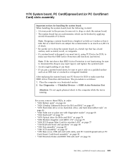
Removal steps of structure frame and IEEE 1394 sub card (continued) In step 10 , remove the system board and the PC Card/ExpressCard (or PC Card/Smart Card) slots assembly from the structure frame together. In step 11 and 12 , remove IEEE 1394 sub card. 10 9 11 12 Step 11 Screw (quantity) M2 × 5 mm, flat-head, nylon-coated (1) Color Black Torque 0.167 Nm (1.7 kgfcm) 100 ThinkPad R61, R61e, and R61i (15.4-inch widescreen) Hardware Maintenance Manual Table 26.
Removal steps of structure frame and IEEE 1394 sub card (continued) In step 10 , remove the system board and the PC Card/ExpressCard (or PC Card/Smart Card) slots assembly from the structure frame together. In step 11 and 12 , remove IEEE 1394 sub card. 10 9 11 12 Step 11 Screw (quantity) M2 × 5 mm, flat-head, nylon-coated (1) Color Black Torque 0.167 Nm (1.7 kgfcm) 100 ThinkPad R61, R61e, and R61i (15.4-inch widescreen) Hardware Maintenance Manual Table 26.
Hardware Maintenance Manual
Page 109
... sure that it only on a horizontal surface. 2. For access, remove these FRUs, in mind. Note: If the test shows that HDD...ThinkPad Devices --> HDD Active Protection Test. v If a system board is as metal, wood, or composite. After replacing the system board, run PC-Doctor for DOS to drop or stack the system board. 1170 System board...v "1060 Keyboard" on page 72 v "1070 Optical drive for R61e and R61i" on page 74 v "1080 Modem daughter card (MDC-1.5)" on page 75 ...Keyboard bezel and speakers" on page 80 v "1120 Fan assembly" on page 83 v "1140 LCD assembly" on page 87 v "1150 Base cover, USB...
... sure that it only on a horizontal surface. 2. For access, remove these FRUs, in mind. Note: If the test shows that HDD...ThinkPad Devices --> HDD Active Protection Test. v If a system board is as metal, wood, or composite. After replacing the system board, run PC-Doctor for DOS to drop or stack the system board. 1170 System board...v "1060 Keyboard" on page 72 v "1070 Optical drive for R61e and R61i" on page 74 v "1080 Modem daughter card (MDC-1.5)" on page 75 ...Keyboard bezel and speakers" on page 80 v "1120 Fan assembly" on page 83 v "1140 LCD assembly" on page 87 v "1150 Base cover, USB...

Hardware Maintenance Manual
Page 110
Removal steps system board, PC Card/ExpressCard (or PC Card/Smart Card) slots assembly 1 1 Step 1 Screw (quantity) M2 × 2.7 mm, flat-head, nylon-coated (2) Color Black Torque 0.167 Nm (1.7 kgfcm) 102 ThinkPad R61, R61e, and R61i (15.4-inch widescreen) Hardware Maintenance Manual a Accelerometer chip for the HDD Active Protection SystemTM b Security chip c CPU d Video chip...
Removal steps system board, PC Card/ExpressCard (or PC Card/Smart Card) slots assembly 1 1 Step 1 Screw (quantity) M2 × 2.7 mm, flat-head, nylon-coated (2) Color Black Torque 0.167 Nm (1.7 kgfcm) 102 ThinkPad R61, R61e, and R61i (15.4-inch widescreen) Hardware Maintenance Manual a Accelerometer chip for the HDD Active Protection SystemTM b Security chip c CPU d Video chip...

Hardware Maintenance Manual
Page 111
R61, R61e, and R61i (15.4-inch widescreen) 103 Removal steps system board, PC Card/ExpressCard (or PC Card/Smart Card) slots assembly (continued) Turn the system board over, and then disconnect the PC Card/ExpressCard slots assembly a from the system board. a 2 When installing: Make sure that the connector of the PC Card/Express Card slot assembly is attached to the system board firmly. Table 27.
R61, R61e, and R61i (15.4-inch widescreen) 103 Removal steps system board, PC Card/ExpressCard (or PC Card/Smart Card) slots assembly (continued) Turn the system board over, and then disconnect the PC Card/ExpressCard slots assembly a from the system board. a 2 When installing: Make sure that the connector of the PC Card/Express Card slot assembly is attached to the system board firmly. Table 27.


