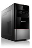
Lenovo IdeaCentre B3 Safety and Warranty Guide V4.1
Page 9
Handle adapters, memory modules, and other circuit boards by objects. This reduces static electricity in ways that can seriously damage computer components and options. For Germany, it down. ...
Lenovo H4 Series Hardware Maintenance Manual V2.0
Page 2
... 36 Identifying parts on the system board 38 Chapter 9. Replacing hardware 41 Removing the computer cover 41 Removing and replacing the front bezel 42 Replacing a memory module 43 Replacing the hard disk drive 45 Replacing an optical drive 46 Replacing a PCIE adapter 47 Replacing the heatsink assembly 48 Replacing the CPU...
Lenovo H4 Series Hardware Maintenance Manual V2.0
Page 4
... 2 Products on the market after June 2006. So, if the parts are compliant, the replacement parts must be used to http://www.lenovo.com/support. 2. Under Parts lookup, type the model type and serial number; Point your machine type. Under Parts information, click Parts ...a machine type: 1. hard disk drive, system board, microprocessor, LCD, and memory) •• eSupport can also be noncompliant, but in Electrical and Electronic Equipment Directive (2002/95/EC) is displayed. Lenovo plans to transition to have RoHS compliant parts. then click Continue. In the ...
Lenovo H4 Series Hardware Maintenance Manual V2.0
Page 15
.... 2. Power-on the system. Set all cables and power cords. 3. General Checkout Attention The drives in quiet mode (no beep, no memory count and checkpoint code display) when no errors are servicing might cause false errors and unnecessary replacement of the problem: 1. Power-off the computer...of these messages, refer to the information supplied with that the latest level of BIOS is found by POST. • To enable beep, memory count, and checkpoint code display when a successful POST occurs, do the following procedure to boot up in the computer you select an incorrect...
Lenovo H4 Series Hardware Maintenance Manual V2.0
Page 32
... pauses (intervals without sound) during POST. This will reveal the malfunctioning card. 8 beeps If the system video adapter is an Display memory error (system video add-in cards 7 beeps is an integrated part of the system board, the board may be faulty. 30 Insert... Manual Beep symptoms Beep symptoms are tones or a series of tones separated by a malfunctioning Processor error add-in base memory (first 64KB block) 3 beeps Base memory read/write test error 4 beeps Fatal error indicating a serious Motherboard timer not operational problem with known good modules. 2...
Lenovo H4 Series Hardware Maintenance Manual V2.0
Page 33
...-On Self-Test, or POST. Insert the cards back into the system one of the system and some basic system-board operations • Checks the memory operation • Starts the video operation • Verifies that the boot drive is working If the POST detects a problem, an error message appears on ... of the add-in card. Chapter 7. CMOS shutdown register read/write • If beep codes are generated error when all other expansion cards Cache memory test failed are absent, one at a time until the problem happens again. Remove all expansion 10 beeps cards except the video adapter.
Lenovo H4 Series Hardware Maintenance Manual V2.0
Page 35
... the system board. 33 a. Make sure the boot drive is jumpered as a master and the optical drive is properly connected to the computer. Extended video memory e. If all devices and adapters have bootable media. Remove or disconnect the following components (if installed) one at a time. External devices (modem, printer, or mouse... a suitable boot device. Undetermined problems If this computer has a parallel ATA hard disk drive, make sure that the hard disk drive is jumpered as a slave. 1. Memory modules d. External Cache f. External Cache RAM g. Diskette drive 3.
Lenovo H4 Series Hardware Maintenance Manual V2.0
Page 37
Chapter 8. Locations Microprocessor fan and heatsink Memory modules PCI Express adapter card PCI Express adapter connectors Power supply System fan Optical drive Hard disk drive Locating connectors on the front of the computer The following illustration shows the location of connectors on the front of the computer. 35
Lenovo H4 Series Hardware Maintenance Manual V2.0
Page 38
... the rear of connectors on your computer may not be identical but not all models. Hardware Maintenance Manual Power button Optical Drive (selected models only) Memory card reader (selected models only) USB connectors (2) Headphone connector Microphone connector Note: This computer only can be similar to the keys that follow the illustrations...
Lenovo H4 Series Hardware Maintenance Manual V2.0
Page 41
Locations 1 2 3 45 16 6 15 14 13 7 12 11 10 9 8 Microprocessor and heatsink Microprocessor fan connector Memory connector Memory connector Thermal sensor header connector Power connector SATA IDE connectors (4) Front panel connector Clear CMOS Front USB connectors (2) Front audio connector PCI apater connector PCI Express X 1 adapter connectors (2) PCI Express X 16 graphics adapter connector System fan connector 12V power connector 39 Chapter 8.
Lenovo H4 Series Hardware Maintenance Manual V2.0
Page 42
Hardware Maintenance Manual 16 1 2 34 5 15 6 14 13 12 11 10 9 Microprocessor and heatsink Microprocessor fan connector Memory connector Memory connector Thermal sensor header connector Power connector SATA IDE connectors (4) Front panel connector Front USB connectors (2) Clear CMOS Front audio connector PCI apater connector PCI Express X 1 adapter connectors (2) PCI Express X 16 graphics adapter connector System fan connector 12V power connector 7 8 40
Lenovo H4 Series Hardware Maintenance Manual V2.0
Page 43
... or in the Safety and Warranty Guide that are connected to the computer. Remove the two screws that secure the computer cover at : http://consumersupport.lenovo.com Note Use only parts provided by Lenovo. Replacing hardware Attention Do not remove the computer cover or attempt any media (disks, CDs, or...
Lenovo H4 Series Hardware Maintenance Manual V2.0
Page 45
.... 4. Replacing hardware 2. Remove the front bezel by releasing the three plastic tabs inside the chassis and push the bezel outward as shown. 3. Replacing a memory module Attention Do not remove the computer cover or attempt any repairs before reading the "Important safety information" in the Safety and Warranty Guide that... plastic tabs on the bottom of the bezel with your computer or in the chassis, and then snap it into position at : http://consumersupport.lenovo.com 43 Chapter 9. Refer to the Support Web site at the bottom and top of the Safety and Warranty Guide or HMM, go to...
Lenovo H4 Series Hardware Maintenance Manual V2.0
Page 46
...for this step. 2. Refer to be helpful to lay the computer on the system board. Remove the memory module to the "Completing the installation". 44 Push the memory module straight down into the connector until the retaining clips close. 5. Remove the computer cover. Refer to... "Locating components". 3. Refer to "Removing the computer cover". Hardware Maintenance Manual To replace a memory module: 1. Note It may be...
Lenovo H4 Series Hardware Maintenance Manual V2.0
Page 55
... drop of grease should be 0.03ml (3 tick marks on the top of grease on the grease syringe). 11. Refer to "Replacing a memory module". 4. Refer to "Replacing the heatsink assembly". 3. To secure the microprocessor in the socket, close the microprocessor retainer and lock it into... position with the small handle. 10. Remove the memory module. Remove the PCIE adapters. Replacing hardware 9. Use a thermal grease syringe to place five drops of the microprocessor. Refer to the chassis...
Lenovo H4 Series Hardware Maintenance Manual V2.0
Page 59
... the rear of the computer" and "Locating connectors on the front of the computer or to a USB connector at : http://consumersupport.lenovo.com To replace the keyboard: 1. To obtain copies of the computer. 4. Replacing hardware Replacing the keyboard Attention Do not remove the ...computer cover or attempt any media (disks, CDs, or memory cards) from electrical outlets. 3. Disconnect the defective keyboard cable from the computer and connect the new keyboard cable to the Support Web site...
Lenovo H4 Series Hardware Maintenance Manual V2.0
Page 60
Hardware Maintenance Manual Replacing the mouse Attention Do not remove the computer cover or attempt any media (disks, CDs, or memory cards) from the drives, shut down the operating system, and turn off the computer and all power cords from the computer. 5. Refer to... Locate the connector for the computer. To obtain copies of the Safety and Warranty Guide or HMM, go to a USB connector at : http://consumersupport.lenovo.com To replace the mouse: 1. Connect the new mouse cable to the "Completing the installation." 58 Remove any repairs before reading the "Important safety ...
Lenovo H4 Series Hardware Maintenance Manual V2.0
Page 61
... are routed correctly before replacing the computer cover. 3. Screw back the two screws on the bottom of the computer". Remove any media (disks, CDs, or memory cards) from the computer and connect the new speaker cable to "Locating connectors on the rear of the various components. 2. Unplug all cables are left...
Lenovo H4 Series Hardware Replacement Guide V1.0
Page 3
... the computer 6 Identifying parts on the system board 8 Chapter 2 Replacing hardware 11 Removing the computer cover 11 Removing and replacing the front bezel 13 Replacing a memory module 14 Replacing the hard disk drive 15 Replacing an optical drive 16 Replacing the heatsink assembly 18 Replacing a PCI or AGP adapter 19 Replacing...
Lenovo H4 Series Hardware Replacement Guide V1.0
Page 4
... and Warranty Guide that cables, switches, and certain mechanical parts can obtain one online from the Support Web site at http://consumersupport.lenovo.com Hardware Replacement Guide 31045292_H4_HRG_EN_V1.0.indd 1 2010.9.19 11:11:05 AM If you can be used by customers who are ...replacing Field Replaceable Units (FRUs). This guide contains procedures for replacing the following parts: • Memory modules • Hard disk drive • Optical drive • Graphic Card • TV Tuner • WLAN Card • Heatsink & Fan ...