User Guide
Page 2
... following basic rules for a replacement. There are frayed power cords and broken plugs. Do not Open the Display. Contact your dealer. Keep children from the wall outlet. There are Dangerous High Voltages inside . Operate the display only from a power source indicated in any way, please contact the manufacturer or the nearest authorized repair service provider for its installation, use another power cord, make sure that have in potential...
... following basic rules for a replacement. There are frayed power cords and broken plugs. Do not Open the Display. Contact your dealer. Keep children from the wall outlet. There are Dangerous High Voltages inside . Operate the display only from a power source indicated in any way, please contact the manufacturer or the nearest authorized repair service provider for its installation, use another power cord, make sure that have in potential...
User Guide
Page 3
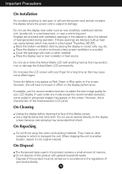
... heat source. If these openings are provided with cloth or other material. Do not rub or strike the Active Matrix LCD with your local authority. Do not press the LCD screen with anything to transport the unit. However, this product contains a small amount of mercury. On Cleaning Unplug the display before cleaning the face of the fixed-resolution LCD panel. Do not use...
... heat source. If these openings are provided with cloth or other material. Do not rub or strike the Active Matrix LCD with your local authority. Do not press the LCD screen with anything to transport the unit. However, this product contains a small amount of mercury. On Cleaning Unplug the display before cleaning the face of the fixed-resolution LCD panel. Do not use...
User Guide
Page 4
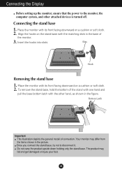
... in the base of the monitor. 3. Place the monitor with the matching slots in the figure. Slots Hook Removing the stand base 1. Place the monitor with the other attached devices is turned off. Do not carry the product upside down holding only the stand base. To remove the stand base, hold the bottom of connection. A3 Connecting the Display Before setting up the monitor, ensure that the power to disconnect...
... in the base of the monitor. 3. Place the monitor with the matching slots in the figure. Slots Hook Removing the stand base 1. Place the monitor with the other attached devices is turned off. Do not carry the product upside down holding only the stand base. To remove the stand base, hold the bottom of connection. A3 Connecting the Display Before setting up the monitor, ensure that the power to disconnect...
User Guide
Page 5
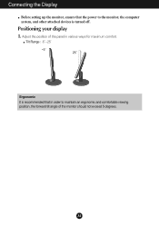
Adjust the position of the monitor should not exceed 5 degrees. Connecting the Display Before setting up the monitor, ensure that in order to the monitor, the computer system, and other attached devices is recommended that the power to maintain an ergonomic and comfortable viewing position, the forward tilt angle of the panel in various ways for maximum comfort. A4 Positioning your display 1. Tilt Range : -5˚~25˚ Ergonomic It is turned off.
Adjust the position of the monitor should not exceed 5 degrees. Connecting the Display Before setting up the monitor, ensure that in order to the monitor, the computer system, and other attached devices is recommended that the power to maintain an ergonomic and comfortable viewing position, the forward tilt angle of the panel in various ways for maximum comfort. A4 Positioning your display 1. Tilt Range : -5˚~25˚ Ergonomic It is turned off.
User Guide
Page 6
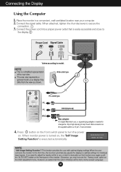
... the user connects the monitor for individual input signals. However, be aware that is executed automatically. Connect the signal cable. Place the monitor in use , a separate plug adapter is a simplified representation of the monitor. NOTE ' Self Image Setting Function'? NOTE This is needed to change the 15 pin high density (3 row) D-sub VGA connector on the front panel of the rear view. Power Cord Signal Cable Varies according to turn the power on the front switch panel to model. Press button...
... the user connects the monitor for individual input signals. However, be aware that is executed automatically. Connect the signal cable. Place the monitor in use , a separate plug adapter is a simplified representation of the monitor. NOTE ' Self Image Setting Function'? NOTE This is needed to change the 15 pin high density (3 row) D-sub VGA connector on the front panel of the rear view. Power Cord Signal Cable Varies according to turn the power on the front switch panel to model. Press button...
User Guide
Page 7
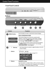
... button to enter or exit the On Screen Display. This feature is D-Sub. OSD LOCKED/UNLOCKED This function allows you to lock the current control settings, so that they cannot be inadvertently changed. Press and hold the MENU button for several seconds. The message "OSD LOCKED" should appear. - + Buttons Use these buttons to select or adjust functions in the On Screen Display. - Control Panel Functions Front Panel Controls Bottom Control Function MENU Button Use this button to make D-Sub or DVI connector...
... button to enter or exit the On Screen Display. This feature is D-Sub. OSD LOCKED/UNLOCKED This function allows you to lock the current control settings, so that they cannot be inadvertently changed. Press and hold the MENU button for several seconds. The message "OSD LOCKED" should appear. - + Buttons Use these buttons to select or adjust functions in the On Screen Display. - Control Panel Functions Front Panel Controls Bottom Control Function MENU Button Use this button to make D-Sub or DVI connector...
User Guide
Page 8
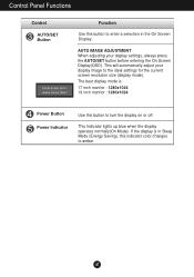
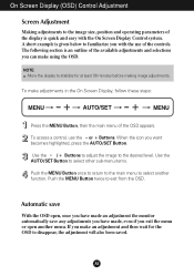
Control Panel Functions Control AUTO/SET Button Function Use this button to enter a selection in Sleep Mode (Energy Saving), this button to the ideal settings for the current screen resolution size (display mode). AUTO IMAGE ADJUSTMENT When adjusting your display image to turn the display on or off. If the display is 17 inch monitor : 1280x1024 19 inch monitor : 1280x1024 Power Button Power Indicator Use this indicator color changes to amber. The best display mode is in the On Screen Display. A7 This Indicator lights up blue when the display operates normally(On Mode). This...
Control Panel Functions Control AUTO/SET Button Function Use this button to enter a selection in Sleep Mode (Energy Saving), this button to the ideal settings for the current screen resolution size (display mode). AUTO IMAGE ADJUSTMENT When adjusting your display image to turn the display on or off. If the display is 17 inch monitor : 1280x1024 19 inch monitor : 1280x1024 Power Button Power Indicator Use this indicator color changes to amber. The best display mode is in the On Screen Display. A7 This Indicator lights up blue when the display operates normally(On Mode). This...
User Guide
Page 9
... make using the OSD. Push the MENU Button twice to the desired level. The following section is quick and easy with the use the - Automatic save With the OSD open another function. NOTE Allow the display to the image size, position and operating parameters of the display is an outline of the available adjustments and selections you exit the menu or open , once you have made an adjustment the monitor...
... make using the OSD. Push the MENU Button twice to the desired level. The following section is quick and easy with the use the - Automatic save With the OSD open another function. NOTE Allow the display to the image size, position and operating parameters of the display is an outline of the available adjustments and selections you exit the menu or open , once you have made an adjustment the monitor...
User Guide
Page 10
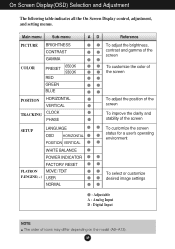
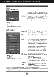
... Sub-menu A D Reference PICTURE BRIGHTNESS CONTRAST GAMMA COLOR PRESET RED GREEN BLUE 6500K 9300K POSITION HORIZONTAL VERTICAL TRACKING CLOCK PHASE To adjust the brightness, contrast and gamma of the screen To customize the color of the screen To adjust the position of the screen To improve the clarity and stability of the screen SETUP LANGUAGE OSD HORIZONTAL POSITION VERTICAL WHITE BALANCE POWER INDICATOR FACTORY RESET FLATRON MOVIE / TEXT F-ENGINE(- ) USER NORMAL To customize the screen status for a user's operating environment To select or customize desired image settings...
... Sub-menu A D Reference PICTURE BRIGHTNESS CONTRAST GAMMA COLOR PRESET RED GREEN BLUE 6500K 9300K POSITION HORIZONTAL VERTICAL TRACKING CLOCK PHASE To adjust the brightness, contrast and gamma of the screen To customize the color of the screen To adjust the position of the screen To improve the clarity and stability of the screen SETUP LANGUAGE OSD HORIZONTAL POSITION VERTICAL WHITE BALANCE POWER INDICATOR FACTORY RESET FLATRON MOVIE / TEXT F-ENGINE(- ) USER NORMAL To customize the screen status for a user's operating environment To select or customize desired image settings...
User Guide
Page 11
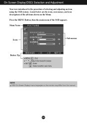
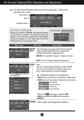
Menu Name PICTURE Icons Sub-menus Button Tip MENU : Exit - + : Adjust (Decrease/Increase) SET : Enter : Select another sub-menu NOTE OSD (On Screen Display) menu languages on the Menu. On Screen Display(OSD) Selection and Adjustment You were introduced to the procedure of the all items shown on the monitor may differ from the manual. Listed below are the icons, icon names, and icon descriptions of selecting and adjusting an item using the OSD system. A10 Press the MENU Button, then the main menu of the OSD appears.
Menu Name PICTURE Icons Sub-menus Button Tip MENU : Exit - + : Adjust (Decrease/Increase) SET : Enter : Select another sub-menu NOTE OSD (On Screen Display) menu languages on the Menu. On Screen Display(OSD) Selection and Adjustment You were introduced to the procedure of the all items shown on the monitor may differ from the manual. Listed below are the icons, icon names, and icon descriptions of selecting and adjusting an item using the OSD system. A10 Press the MENU Button, then the main menu of the OSD appears.
User Guide
Page 12
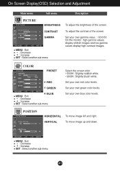
... the monitor, high gamma values display whitish images and low gamma values display high contrast images. POSITION POSITION HORIZONTAL VERTICAL To move image up and down. Set your own green color levels. To move image left and right. MENU : Exit +- : Decrease : Increase SET : Select another sub-menu Select the screen color. • 6500K: Slightly reddish white. • 9300K: Slightly bluish white. Set your own red color levels. On Screen Display(OSD) Selection and Adjustment Main menu Sub menu Description PICTURE PICTURE BRIGHTNESS CONTRAST GAMMA MENU : Exit...
... the monitor, high gamma values display whitish images and low gamma values display high contrast images. POSITION POSITION HORIZONTAL VERTICAL To move image up and down. Set your own green color levels. To move image left and right. MENU : Exit +- : Decrease : Increase SET : Select another sub-menu Select the screen color. • 6500K: Slightly reddish white. • 9300K: Slightly bluish white. Set your own red color levels. On Screen Display(OSD) Selection and Adjustment Main menu Sub menu Description PICTURE PICTURE BRIGHTNESS CONTRAST GAMMA MENU : Exit...
User Guide
Page 13
... image of the monitor to video signal distortion. Press the + button to fit into the standard output level of the OSD window POSITION on the front side of characters. This function will automatically be enabled only when the input signal is an analog signal. If you to remove any time, the power indicator will be turned on. FACTORY RESET Restore all factory default settings except "LANGUAGE." SETUP Hz + SET WHITE BALANCE Hz MENU - + SET POWER MENU : Exit +- : Adjust : Adjust INDICATOR SET...
... image of the monitor to video signal distortion. Press the + button to fit into the standard output level of the OSD window POSITION on the front side of characters. This function will automatically be enabled only when the input signal is an analog signal. If you to remove any time, the power indicator will be turned on. FACTORY RESET Restore all factory default settings except "LANGUAGE." SETUP Hz + SET WHITE BALANCE Hz MENU - + SET POWER MENU : Exit +- : Adjust : Adjust INDICATOR SET...
User Guide
Page 14
... FLATRON f-ENGINE When you easily select the best desired TEXT image condition optimized to use the adjusted screen. To adjust the USER sub-menu function, Press the SET Button (Brightness): Adjusts screen brightness. A13 ACE(Adaptive Clarity Enhancer) Selects the clarity mode. MOVIE For animation images in videos or movies TEXT For text images (Word processing etc.) USER User You can save the YES value using a different environment setting. RCM(Real Color Management) Selects the color mode. 0 Not applied 1 Green...
... FLATRON f-ENGINE When you easily select the best desired TEXT image condition optimized to use the adjusted screen. To adjust the USER sub-menu function, Press the SET Button (Brightness): Adjusts screen brightness. A13 ACE(Adaptive Clarity Enhancer) Selects the clarity mode. MOVIE For animation images in videos or movies TEXT For text images (Word processing etc.) USER User You can save the YES value using a different environment setting. RCM(Real Color Management) Selects the color mode. 0 Not applied 1 Green...
User Guide
Page 15
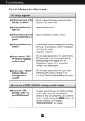
... bring up the screen. Troubleshooting Check the following before calling for several seconds: the message "OSD UNLOCKED" will appear. If the display is out of horizontal or vertical frequency range of the display connected? See the 'Specifications' section of this manual and configure your display is connected properly to turn on the screen? Do you see if the power cord is not connected. This message appears when the signal cable between your PC...
... bring up the screen. Troubleshooting Check the following before calling for several seconds: the message "OSD UNLOCKED" will appear. If the display is out of horizontal or vertical frequency range of the display connected? See the 'Specifications' section of this manual and configure your display is connected properly to turn on the screen? Do you see if the power cord is not connected. This message appears when the signal cable between your PC...
User Guide
Page 16
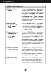
Troubleshooting Display image is incorrect Display Position is mono or abnormal. Press the AUTO/SET button to automatically adjust your display image to the ideal setting. The screen color is incorrect. Set the color setting higher than 24 bits (true color). A15 Settings. Check Control Panel --> Display --> Settings and see if the frequency or the resolution were changed. Check Control Panel --> Display --> Settings and adjust the display to the recommended resolution or adjust the display image to the ideal setting. If yes, readjust the video card to the ...
Troubleshooting Display image is incorrect Display Position is mono or abnormal. Press the AUTO/SET button to automatically adjust your display image to the ideal setting. The screen color is incorrect. Set the color setting higher than 24 bits (true color). A15 Settings. Check Control Panel --> Display --> Settings and see if the frequency or the resolution were changed. Check Control Panel --> Display --> Settings and adjust the display to the recommended resolution or adjust the display image to the ideal setting. If yes, readjust the video card to the ...
User Guide
Page 17
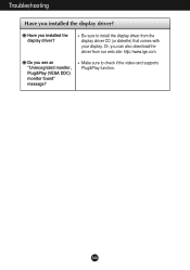
Have you see an "Unrecognized monitor, Plug&Play (VESA DDC) monitor found" message? Do you installed the display driver? Be sure to check if the video card supports Plug&Play function. Or, you installed the display driver? Make sure to install the display driver from our web site: http://www.lge.com. A16 Troubleshooting Have you can also download the driver from the display driver CD (or diskette) that comes with your display.
Have you see an "Unrecognized monitor, Plug&Play (VESA DDC) monitor found" message? Do you installed the display driver? Be sure to check if the video card supports Plug&Play function. Or, you installed the display driver? Make sure to install the display driver from our web site: http://www.lge.com. A16 Troubleshooting Have you can also download the driver from the display driver CD (or diskette) that comes with your display.
User Guide
Page 18
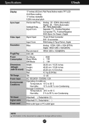
... ˚C Humidity 5 % to 95 % non-Condensing Attached( ), Detachable ( O ) Attached( O ), Detachable ( ) Wall-outlet type or PC-outlet type NOTE Information in this document is subject to change without notice. Specifications 17inch Display Sync Input Video Input Resolution Plug&Play Power Consumption Dimensions &Weight (with tilt stand) Tilt Range Power Input Environmental Conditions Tilt Stand Signal cable Power cord 17 inches (43.2cm) Flat Panel Active matrix-TFT LCD Anti-Glare coating 17 inches viewable 0.264 mm pixel pitch Horizontal Freq. A17 Vertical Freq.
... ˚C Humidity 5 % to 95 % non-Condensing Attached( ), Detachable ( O ) Attached( O ), Detachable ( ) Wall-outlet type or PC-outlet type NOTE Information in this document is subject to change without notice. Specifications 17inch Display Sync Input Video Input Resolution Plug&Play Power Consumption Dimensions &Weight (with tilt stand) Tilt Range Power Input Environmental Conditions Tilt Stand Signal cable Power cord 17 inches (43.2cm) Flat Panel Active matrix-TFT LCD Anti-Glare coating 17 inches viewable 0.264 mm pixel pitch Horizontal Freq. A17 Vertical Freq.
User Guide
Page 19
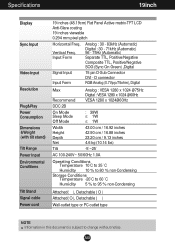
... TTL, Positive/Negative SOG (Sync On Green) ,Digital Signal Input Input Form 15 pin D-Sub Connector DVI - Vertical Freq. Specifications 19inch Display Sync Input Video Input Resolution Plug&Play Power Consumption Dimensions &Weight (with tilt stand) Tilt Range Power Input Environmental Conditions Tilt Stand Signal cable Power cord 19 inches (48.19cm) Flat Panel Active matrix-TFT LCD Anti-Glare coating 19 inches viewable 0.294 mm pixel pitch Horizontal Freq. A18 D connector RGB Analog (0.7Vp-p/75ohm), Digital Max Recommend DDC 2B Analog : VESA 1280 x 1024 @75Hz Digital : VESA 1280...
... TTL, Positive/Negative SOG (Sync On Green) ,Digital Signal Input Input Form 15 pin D-Sub Connector DVI - Vertical Freq. Specifications 19inch Display Sync Input Video Input Resolution Plug&Play Power Consumption Dimensions &Weight (with tilt stand) Tilt Range Power Input Environmental Conditions Tilt Stand Signal cable Power cord 19 inches (48.19cm) Flat Panel Active matrix-TFT LCD Anti-Glare coating 19 inches viewable 0.294 mm pixel pitch Horizontal Freq. A18 D connector RGB Analog (0.7Vp-p/75ohm), Digital Max Recommend DDC 2B Analog : VESA 1280 x 1024 @75Hz Digital : VESA 1280...
User Guide
Page 20
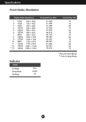
Specifications Preset Modes (Resolution) Display Modes (Resolution) 1 VGA 640 x 350 2 VGA 720 x 400 3 VGA 640 x 480 4 VESA 640 x 480 5 VESA 800 x 600 6 VESA 800 x 600 7 MAC 832 x 624 8 VESA 1024 x 768 9 VESA 1024 x 768 10 MAC 1152 x 870 11 VESA 1152 x 900 *12 VESA 1280 x 1024 **13 VESA 1280 x 1024 Horizontal Freq. (kHz) 31.469 31.468 31.469 37.500 37.879 46.875 49.725 48.363 60.023 68.681 61.805 63.981 79.976 Vertical Freq. (Hz) 70 70 60 75 60 75 75 60 75 75 65 60 75 Indicator MODE On Mode Sleep Mode Off Mode blue amber off * Recommend Mode ** Only Analog Mode A19
Specifications Preset Modes (Resolution) Display Modes (Resolution) 1 VGA 640 x 350 2 VGA 720 x 400 3 VGA 640 x 480 4 VESA 640 x 480 5 VESA 800 x 600 6 VESA 800 x 600 7 MAC 832 x 624 8 VESA 1024 x 768 9 VESA 1024 x 768 10 MAC 1152 x 870 11 VESA 1152 x 900 *12 VESA 1280 x 1024 **13 VESA 1280 x 1024 Horizontal Freq. (kHz) 31.469 31.468 31.469 37.500 37.879 46.875 49.725 48.363 60.023 68.681 61.805 63.981 79.976 Vertical Freq. (Hz) 70 70 60 75 60 75 75 60 75 75 65 60 75 Indicator MODE On Mode Sleep Mode Off Mode blue amber off * Recommend Mode ** Only Analog Mode A19
User Guide
Page 22
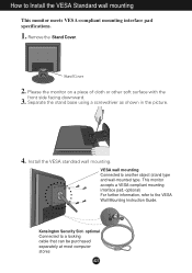
...- Please the monitor on a piece of cloth or other soft surface with the front side facing downward. 3. Install the VESA standrad wall mounting. Remove the Stand Cover. optional Connected to the VESA Wall Mounting Instruction Guide. This monitor accepts a VESA-compliant mounting interface pad.-optional) For further information, refer to a locking cable that can be purchased separately at most computer stores A21 Separate the stand base using a screwdriver as shown in the picture. 4. Stand Cover 2.
...- Please the monitor on a piece of cloth or other soft surface with the front side facing downward. 3. Install the VESA standrad wall mounting. Remove the Stand Cover. optional Connected to the VESA Wall Mounting Instruction Guide. This monitor accepts a VESA-compliant mounting interface pad.-optional) For further information, refer to a locking cable that can be purchased separately at most computer stores A21 Separate the stand base using a screwdriver as shown in the picture. 4. Stand Cover 2.


