Service Manual
Page 2
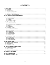
... PARTS ...5 2.1.1 FRONT GRILLE ...5 2.1.2 CABINET...5 2.1.3 CONTROL BOARD ...5 2.2 AIR HANDLING PARTS ...6 2.2.1 AIR GUIDE UPPER ...6 2.2.2 ORIFICE, TURBO FAN AND FAN ...6 2.2.3 MOTOR ...7 2.2.4 AIR GUIDE ...7 2.3 ELECTRICAL PARTS ...7 2.3.1 OVERLOAD PROTECTOR ...7 2.3.2 COMPRESSOR ...8 2.3.3 CAPACITOR ...8 2.3.4 THERMOSTAT ...8 2.3.5 ROTARY SWITCH ...8 2.3.6 POWER CORD ...9 2.4 REFRIGERANT CYCLE ...9 2.4.1 CONDENSER ...9 2.4.2 EVAPORATOR ...10 2.4.3 CAPILLARY TUBE ...10 3. CIRCUIT DIAGRAM ...22 6.
... PARTS ...5 2.1.1 FRONT GRILLE ...5 2.1.2 CABINET...5 2.1.3 CONTROL BOARD ...5 2.2 AIR HANDLING PARTS ...6 2.2.1 AIR GUIDE UPPER ...6 2.2.2 ORIFICE, TURBO FAN AND FAN ...6 2.2.3 MOTOR ...7 2.2.4 AIR GUIDE ...7 2.3 ELECTRICAL PARTS ...7 2.3.1 OVERLOAD PROTECTOR ...7 2.3.2 COMPRESSOR ...8 2.3.3 CAPACITOR ...8 2.3.4 THERMOSTAT ...8 2.3.5 ROTARY SWITCH ...8 2.3.6 POWER CORD ...9 2.4 REFRIGERANT CYCLE ...9 2.4.1 CONDENSER ...9 2.4.2 EVAPORATOR ...10 2.4.3 CAPILLARY TUBE ...10 3. CIRCUIT DIAGRAM ...22 6.

Service Manual
Page 6
Replace the grille by pulling them off. Remove the front grille. (Refer to section 2.1.1) 3. NOTE : Controls, wires, and capacitor are now accessible for the fan motor and compressor. (See Figure 5) 7. Discharge the capacitor before servicing. Remove the two knobs by placing the tabs in this manual or inside control board.) Figure 3 Figure 4 Figure...
Replace the grille by pulling them off. Remove the front grille. (Refer to section 2.1.1) 3. NOTE : Controls, wires, and capacitor are now accessible for the fan motor and compressor. (See Figure 5) 7. Discharge the capacitor before servicing. Remove the two knobs by placing the tabs in this manual or inside control board.) Figure 3 Figure 4 Figure...
Service Manual
Page 9
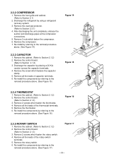
... Remove 3 nuts which fasten the rotary switch. 4. Remove the control board. (Refer to Section 2.1.2) 2. Remove all the leads of capacitor terminals. 6. Remove the compressor. 7. Remove all the leads of the thermostat terminals. 5. Remove the control board. (Refer to Section ... Discharge the refrigerant by referring to the removal procedure above . (See Figure 14) 2.3.3 CAPACITOR 1. Re-install the components by placing a 20 KΩ resistor across the capacitor terminals. 4. After discharging the unit completely, unbrace the suction and discharge pipes at the ...
... Remove 3 nuts which fasten the rotary switch. 4. Remove the control board. (Refer to Section 2.1.2) 2. Remove all the leads of capacitor terminals. 6. Remove the compressor. 7. Remove all the leads of the thermostat terminals. 5. Remove the control board. (Refer to Section ... Discharge the refrigerant by referring to the removal procedure above . (See Figure 14) 2.3.3 CAPACITOR 1. Re-install the components by placing a 20 KΩ resistor across the capacitor terminals. 4. After discharging the unit completely, unbrace the suction and discharge pipes at the ...

Service Manual
Page 19
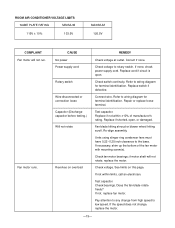
...Replacement. Check of power source. Check control switch. Check of circuit breaker and fuse. Improper wiring. Regular but fails to start . Check of compressor capacitor. Defect of control switch setting. Improper thermostat setting Loose terminal connection Improper wiring Irregular motor resistance (Ω) Irregular motor insulation (Ω) Replacement of thermostat....Start Compressor fails only to start . Gas leakage of feeler bulb of compressor (Motor damaged). -18- Replacement of compressor. (Locking of fan motor capacitor. Defect of piston, metal.)
...Replacement. Check of power source. Check control switch. Check of circuit breaker and fuse. Improper wiring. Regular but fails to start . Check of compressor capacitor. Defect of control switch setting. Improper thermostat setting Loose terminal connection Improper wiring Irregular motor resistance (Ω) Irregular motor insulation (Ω) Replacement of thermostat....Start Compressor fails only to start . Gas leakage of feeler bulb of compressor (Motor damaged). -18- Replacement of compressor. (Locking of fan motor capacitor. Defect of piston, metal.)
Service Manual
Page 20
... shim up the bottom of manufacturer's rating. Does the fan blade rotate freely? Correct if none. Repair or replace loose terminal. Test capacitor. Replace if not within limits, call an electrician. if motor shaft will not run. Check voltage to wiring diagram for terminal identification.... If none, check power supply cord. Replace if shorted, open . Fan blade hitting shroud or blower wheel hitting scroll. Check voltage. Test capacitor. Check bearings. If not, replace fan motor. Pay attention to any change , replace the motor. -19- If the speed does not change...
... shim up the bottom of manufacturer's rating. Does the fan blade rotate freely? Correct if none. Repair or replace loose terminal. Test capacitor. Replace if not within limits, call an electrician. if motor shaft will not run. Check voltage to wiring diagram for terminal identification.... If none, check power supply cord. Replace if shorted, open . Fan blade hitting shroud or blower wheel hitting scroll. Check voltage. Test capacitor. Check bearings. If not, replace fan motor. Pay attention to any change , replace the motor. -19- If the speed does not change...
Service Manual
Page 21
..., correct the connections. Replace if not within ±10% of manufacturer's rating, replace if shorted, open . Replace if open circuit or ground. Capacitor (discharge capacitor before servicing.) Check the capacitor. If voltage is high, remove the overload, cool, and retest.) -20- Check for continuity, refer to wiring diagram for identification, and replace the...
..., correct the connections. Replace if not within ±10% of manufacturer's rating, replace if shorted, open . Replace if open circuit or ground. Capacitor (discharge capacitor before servicing.) Check the capacitor. If voltage is high, remove the overload, cool, and retest.) -20- Check for continuity, refer to wiring diagram for identification, and replace the...
Service Manual
Page 22
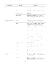
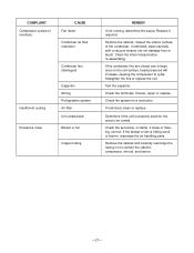
...loose, repair or replace. Check the system for the area to cycle. If the blower or fan is properly sized for a restriction. Test the capacitor. Replace if required. Straighten the fins or replace the coil. If restricted, clean or replace. Check the set screw, or clamp. Remove the...increase, causing the compressor to be cooled. CAUSE Fan motor Condenser air flow restriction Insufficient cooling Excessive noise Condenser fins (damaged) Capacitor Wiring Refrigeration system Air filter Unit undersized Blower or fan Copper tubing REMEDY If not running, determine the cause.
...loose, repair or replace. Check the system for the area to cycle. If the blower or fan is properly sized for a restriction. Test the capacitor. Replace if required. Straighten the fins or replace the coil. If restricted, clean or replace. Check the set screw, or clamp. Remove the...increase, causing the compressor to be cooled. CAUSE Fan motor Condenser air flow restriction Insufficient cooling Excessive noise Condenser fins (damaged) Capacitor Wiring Refrigeration system Air filter Unit undersized Blower or fan Copper tubing REMEDY If not running, determine the cause.
Service Manual
Page 23
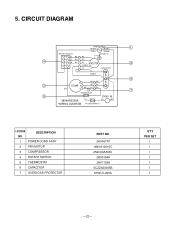
...) 1 (Plain) (Ribbed) ROTARY SWITCH GN(GN/YL) 1 2 H BK BK 3 4 L RD RD 4 5 6 M BL BL MOTOR 2 7 8 OR(BR) YL CAPACITOR YL F OR(BR) C 6 R BK BK 3 COMP. DESCRIPTION 1 POWER CORD ASSY 2 FAN MOTOR 3 COMPRESSOR 4 ROTARY SWITCH 5 THERMOSTAT 6 CAPACITOR 7 OVERLOAD PROTECTOR PART NO. 2H00677P 4681A10016C 2520UCAA003 2H00154H 2H01109H 0CZZA20005B 6750U-L050A Q'TY PER SET 1 1 1 1 1 1 1 -22- M. 3854AR2330A...
...) 1 (Plain) (Ribbed) ROTARY SWITCH GN(GN/YL) 1 2 H BK BK 3 4 L RD RD 4 5 6 M BL BL MOTOR 2 7 8 OR(BR) YL CAPACITOR YL F OR(BR) C 6 R BK BK 3 COMP. DESCRIPTION 1 POWER CORD ASSY 2 FAN MOTOR 3 COMPRESSOR 4 ROTARY SWITCH 5 THERMOSTAT 6 CAPACITOR 7 OVERLOAD PROTECTOR PART NO. 2H00677P 4681A10016C 2520UCAA003 2H00154H 2H01109H 0CZZA20005B 6750U-L050A Q'TY PER SET 1 1 1 1 1 1 1 -22- M. 3854AR2330A...
Service Manual
Page 25
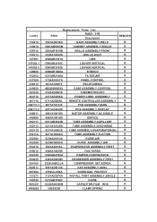
...,COMPRESSOR 5403A20009N CONDENSER ASSEMBLY,FIRST 2520UABC2JA COMPRESSOR SET,KOREA 5901A20011B FAN ASSEMBLY,AXIAL 6750U-L050A OVERLOAD PROTECT 3127A20074A INSTALL PART ASSEMBLY,SINGLE 5210AR3196C 0CZZA20005B GUIDE CAPACITOR,FILM,BOX 3H02932B CLAMP,SPRING REMARK R R R R R R R R R R R R R R R R R R R R R R R R R R R R R R R R R R R R
...,COMPRESSOR 5403A20009N CONDENSER ASSEMBLY,FIRST 2520UABC2JA COMPRESSOR SET,KOREA 5901A20011B FAN ASSEMBLY,AXIAL 6750U-L050A OVERLOAD PROTECT 3127A20074A INSTALL PART ASSEMBLY,SINGLE 5210AR3196C 0CZZA20005B GUIDE CAPACITOR,FILM,BOX 3H02932B CLAMP,SPRING REMARK R R R R R R R R R R R R R R R R R R R R R R R R R R R R R R R R R R R R
Service Manual
Page 26
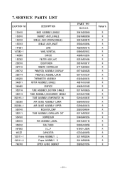
... SINGLE TUBE ASSEMBLY,EVAPORATOR IN AIR GUIDE ASSEMBLY LOWER AIR GUIDE ASSEMBLY UPPER ISOLATOR,COMP TUBE ASSEMBLY,CAPILLARY OUT COMPRESSOR FAN ASSEMBLY,AXIAL FAN,TURBO O.L.P CAPACITOR Frame ASSEMBLY L Frame ASSEMBLY R UPPER GUIDE CABINET PART NO RAD-61A 3041A20036N 3091AR6055M 3531A20087B 3530A10039A 4520AR3191A 5990AR3190C 4998A10025A 5231AR2148A 3831A10001F 6711A20066C 6871A20432B 6871A10123F 6323A20003S 4681A10016M...
... SINGLE TUBE ASSEMBLY,EVAPORATOR IN AIR GUIDE ASSEMBLY LOWER AIR GUIDE ASSEMBLY UPPER ISOLATOR,COMP TUBE ASSEMBLY,CAPILLARY OUT COMPRESSOR FAN ASSEMBLY,AXIAL FAN,TURBO O.L.P CAPACITOR Frame ASSEMBLY L Frame ASSEMBLY R UPPER GUIDE CABINET PART NO RAD-61A 3041A20036N 3091AR6055M 3531A20087B 3530A10039A 4520AR3191A 5990AR3190C 4998A10025A 5231AR2148A 3831A10001F 6711A20066C 6871A20432B 6871A10123F 6323A20003S 4681A10016M...


