Owner's Manual
Page 3
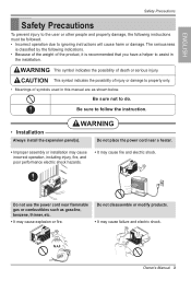
... or installation may cause incorrect operation, including injury, fire, and poor performance electric shock hazards. • It may cause fire and electric shock. Do not disassemble or modify products. • It may cause explosion or fire. Be sure not to assist in this manual are as gasoline, benzene, thinner, etc. •...
... or installation may cause incorrect operation, including injury, fire, and poor performance electric shock hazards. • It may cause fire and electric shock. Do not disassemble or modify products. • It may cause explosion or fire. Be sure not to assist in this manual are as gasoline, benzene, thinner, etc. •...
Service Manual
Page 2
......3 1.2 SPECIFICATIONS ...3 1.3 LOCATIONS OF CONTROLS ...4 1.4 SAFETY PRECAUTIONS ...4 1.5 INSULATION RESISTANCE TEST ...4 2. TROUBLESHOOTING GUIDE ...15 4.1 OUTSIDE DIMENSIONS...15 4.2 PIPING SYSTEM ...16 4.3 TROUBLESHOOTING GUIDE ...17 5. CIRCUIT DIAGRAM ...22 6. CONTENTS 1. DISASSEMBLY INSTRUCTIONS 5 2.1 MECHANICAL PARTS ...5 2.1.1 FRONT GRILLE ...5 2.1.2 CABINET...5 2.1.3 CONTROL BOARD ...5 2.2 AIR HANDLING PARTS ...6 2.2.1 AIR GUIDE UPPER ...6 2.2.2 ORIFICE, TURBO FAN AND FAN ...6 2.2.3 MOTOR ...7 2.2.4 AIR GUIDE ...7 2.3 ELECTRICAL PARTS ...7 2.3.1 OVERLOAD...
......3 1.2 SPECIFICATIONS ...3 1.3 LOCATIONS OF CONTROLS ...4 1.4 SAFETY PRECAUTIONS ...4 1.5 INSULATION RESISTANCE TEST ...4 2. TROUBLESHOOTING GUIDE ...15 4.1 OUTSIDE DIMENSIONS...15 4.2 PIPING SYSTEM ...16 4.3 TROUBLESHOOTING GUIDE ...17 5. CIRCUIT DIAGRAM ...22 6. CONTENTS 1. DISASSEMBLY INSTRUCTIONS 5 2.1 MECHANICAL PARTS ...5 2.1.1 FRONT GRILLE ...5 2.1.2 CABINET...5 2.1.3 CONTROL BOARD ...5 2.2 AIR HANDLING PARTS ...6 2.2.1 AIR GUIDE UPPER ...6 2.2.2 ORIFICE, TURBO FAN AND FAN ...6 2.2.3 MOTOR ...7 2.2.4 AIR GUIDE ...7 2.3 ELECTRICAL PARTS ...7 2.3.1 OVERLOAD...

Service Manual
Page 6
... 3 Figure 4 Figure 5 -5- Disconnect the unit from source of power. 2. Remove 2 screws that secure the cabinet to Section 2.1.1) 3. Disconnect one housing terminal and 3 wires for procedures. 6. DISASSEMBLY INSTRUCTIONS 2.1 MECHANICAL PARTS 2.1.1 FRONT GRILLE 1. Replace the grille by referring to control board. (See Figure 1) 3. Remove the front grille. (Refer to base pan and air...
... 3 Figure 4 Figure 5 -5- Disconnect the unit from source of power. 2. Remove 2 screws that secure the cabinet to Section 2.1.1) 3. Disconnect one housing terminal and 3 wires for procedures. 6. DISASSEMBLY INSTRUCTIONS 2.1 MECHANICAL PARTS 2.1.1 FRONT GRILLE 1. Replace the grille by referring to control board. (See Figure 1) 3. Remove the front grille. (Refer to base pan and air...
