
Service Manual
Page 1
MODEL : DLE5977W/DLG5988W DLE5977B/DLG5988B DLE3777W/DLG3788W DLE5977WM/DLG5988WM DLE5977SM/DLG5988SM Website:http://www.LGservice.com [For U.S.A] www.lg.ca [For Canada] ELECTRIC & GAS DRYER SERVICE MANUAL CAUTION READ THIS MANUAL CAREFULLY TO DIAGNOSE TROUBLES CORRECTLY BEFORE OFFERING SERVICE.
MODEL : DLE5977W/DLG5988W DLE5977B/DLG5988B DLE3777W/DLG3788W DLE5977WM/DLG5988WM DLE5977SM/DLG5988SM Website:http://www.LGservice.com [For U.S.A] www.lg.ca [For Canada] ELECTRIC & GAS DRYER SERVICE MANUAL CAUTION READ THIS MANUAL CAREFULLY TO DIAGNOSE TROUBLES CORRECTLY BEFORE OFFERING SERVICE.

Service Manual
Page 3
FEATURES AND BENEFITS ...6 3. DRYER CYCLE PROCESS ...13 5. TEST 3 MOTOR TEST 23 9-4. ELECTRIC TYPE 26 9-7. CHANGE GAS SETTING (NATURAL GAS, PROPANE GAS 28 11. CONTROL PANEL & PLATE ASSEMBLY 37 12-2. ...
FEATURES AND BENEFITS ...6 3. DRYER CYCLE PROCESS ...13 5. TEST 3 MOTOR TEST 23 9-4. ELECTRIC TYPE 26 9-7. CHANGE GAS SETTING (NATURAL GAS, PROPANE GAS 28 11. CONTROL PANEL & PLATE ASSEMBLY 37 12-2. ...

Service Manual
Page 4
1 SPECIFICATIONS I Name : Electric and Gas Dryer I Power supply : Please refer to change by manufacturer. I ACESSORIES Dryer rack (1 each ) Purchased Separately See page 8 for how to use . I Dryer capacity : IEC 7.3cu.ft. Stacking kit (1 each) Purchased Separately See page 7 for how to use. 4 Pedestal (1 each ) See page 6 for how to use . I Size : 68.6X98.3X76.1 (cm) I Weight : 126 (Ibs) Specifications are subject to the rating label regarding detailed information.
1 SPECIFICATIONS I Name : Electric and Gas Dryer I Power supply : Please refer to change by manufacturer. I ACESSORIES Dryer rack (1 each ) Purchased Separately See page 8 for how to use . I Dryer capacity : IEC 7.3cu.ft. Stacking kit (1 each) Purchased Separately See page 7 for how to use. 4 Pedestal (1 each ) See page 6 for how to use . I Size : 68.6X98.3X76.1 (cm) I Weight : 126 (Ibs) Specifications are subject to the rating label regarding detailed information.
Service Manual
Page 5
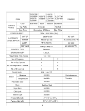
.... of Programs 9 7 No. of Dry Levels 5 5 Sound levels High / Low / Off Sensor Moisture Temperature Avaiable Avaiable Electrode sensor Termistor Reversible Door Avaiable Drum Stainless Steel Dryer Rack Child Lock Avaiable Avaiable Interior Light Product (WxHxD) Packing (WxHxD) Avaiable 27" x 42 3/4 x 28 1/3 29 1/2" x 44 3/4 x 30 3/4 5 of Dry Options 5 5 No. ITEM DLE5977WM DLE5977S...
.... of Programs 9 7 No. of Dry Levels 5 5 Sound levels High / Low / Off Sensor Moisture Temperature Avaiable Avaiable Electrode sensor Termistor Reversible Door Avaiable Drum Stainless Steel Dryer Rack Child Lock Avaiable Avaiable Interior Light Product (WxHxD) Packing (WxHxD) Avaiable 27" x 42 3/4 x 28 1/3 29 1/2" x 44 3/4 x 30 3/4 5 of Dry Options 5 5 No. ITEM DLE5977WM DLE5977S...
Service Manual
Page 6
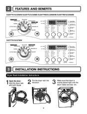
Hold the dryer rack with both hands. 2 Put the dryer rack into the drum 3 Make sure that dryer is evenly placed right onto the drum inside and door rim. 6 2 FEATURES AND BENEFITS DLE5977W/DLG5988W/DLE5977B/DLG5988B/DLE5977WM/DLG5988WM/DLE5977SM/DLG5988SM DLE3777W/DLG3788W 3 INSTALLATION INSTRUCTIONS Dryer Rack Installation Instructions 1Open the door.
Hold the dryer rack with both hands. 2 Put the dryer rack into the drum 3 Make sure that dryer is evenly placed right onto the drum inside and door rim. 6 2 FEATURES AND BENEFITS DLE5977W/DLG5988W/DLE5977B/DLG5988B/DLE5977WM/DLG5988WM/DLE5977SM/DLG5988SM DLE3777W/DLG3788W 3 INSTALLATION INSTRUCTIONS Dryer Rack Installation Instructions 1Open the door.
Service Manual
Page 7
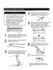
... tape from the stacking kit side bracket. 6 Insert the front stacking kit. be performed by 2 or more experienced service personnel. 5 Place the dryer on top of bracket. Push the front stacking kit back to the stoppers of side stacking kit. 3 Fit the stacking kit side bracket firmly to...kit. 1 Stacking kit Place washer firmly on the back of the washer by attaching the doublefaced tape to pinch fingers between the washer and dryer. Slide washer slowly backwards to the side of top plate by fitting legs as picture shows. 7 Screw both sides of installation makes the stacking...
... tape from the stacking kit side bracket. 6 Insert the front stacking kit. be performed by 2 or more experienced service personnel. 5 Place the dryer on top of bracket. Push the front stacking kit back to the stoppers of side stacking kit. 3 Fit the stacking kit side bracket firmly to...kit. 1 Stacking kit Place washer firmly on the back of the washer by attaching the doublefaced tape to pinch fingers between the washer and dryer. Slide washer slowly backwards to the side of top plate by fitting legs as picture shows. 7 Screw both sides of installation makes the stacking...
Service Manual
Page 8
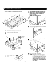
... appliance. 6 Install the eight (8) screws(supplied) to attach the brackets to the pedestal. Pedestal Installation Instructions For washer, dryer, and combo LG 27 4 Attach the double-faced tape of the bracket to the dryer as shown so the bent parts of the brackets align with the edge and can be placed on top... of the pedestal. , for washer/ combo for dryer 5 Be sure to press the adhesive parts of the appliance and pedestal...
... appliance. 6 Install the eight (8) screws(supplied) to attach the brackets to the pedestal. Pedestal Installation Instructions For washer, dryer, and combo LG 27 4 Attach the double-faced tape of the bracket to the dryer as shown so the bent parts of the brackets align with the edge and can be placed on top... of the pedestal. , for washer/ combo for dryer 5 Be sure to press the adhesive parts of the appliance and pedestal...
Service Manual
Page 9
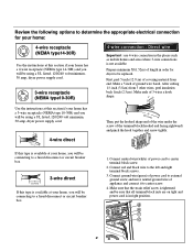
... is available at your home has a 3-wire receptacle (NEMA type 10-30R) and you will be using a UL listed, 120/240 volt minimum, 30 amp, dryer power supply cord. 5" (12.7 cm) 31/2" (8.6 cm) 1" (2.5 cm) (12.75c" m) 1" (2.5 cm) 4-wire direct 3V2" (8.9 cm) 4-wire ... screw of appliance and connect it to center screw. 4. d e f c b 9 Review the following options to determine the appropriate electrical connection for dryer to be replaced. you will be connecting box to a fused(21d.5"icsmc)onnect or circuit breaker (12.75c" m) 1" (2.5 cm) 3V2" (8.9 cm...
... is available at your home has a 3-wire receptacle (NEMA type 10-30R) and you will be using a UL listed, 120/240 volt minimum, 30 amp, dryer power supply cord. 5" (12.7 cm) 31/2" (8.6 cm) 1" (2.5 cm) (12.75c" m) 1" (2.5 cm) 4-wire direct 3V2" (8.9 cm) 4-wire ... screw of appliance and connect it to center screw. 4. d e f c b 9 Review the following options to determine the appropriate electrical connection for dryer to be replaced. you will be connecting box to a fused(21d.5"icsmc)onnect or circuit breaker (12.75c" m) 1" (2.5 cm) 3V2" (8.9 cm...

Service Manual
Page 10
...b d 1. Connect ground wire(green) of power cord to external ground screw and move neutral ground wire of a 3 wire connection, or you are installing your dryer in a mobile home, you must use 3-wire connection in right position. Connect red and black wire to center screw. 4. Option 1: 4-wire connection with a ...a 4wire connection. 1. Make sure that all terminal block nuts are on 10 tight and power cord is in order for cm) dryer to center terminal block screw. 2. Connect neutral wire(white) of the terminal block(hooked end facing rightward) and pinch the hook ...
...b d 1. Connect ground wire(green) of power cord to external ground screw and move neutral ground wire of a 3 wire connection, or you are installing your dryer in a mobile home, you must use 3-wire connection in right position. Connect red and black wire to center screw. 4. Option 1: 4-wire connection with a ...a 4wire connection. 1. Make sure that all terminal block nuts are on 10 tight and power cord is in order for cm) dryer to center terminal block screw. 2. Connect neutral wire(white) of the terminal block(hooked end facing rightward) and pinch the hook ...

Service Manual
Page 12
...Tighten all pipe connections (internal & external) for checking inlet gas pressure) 3 Equipment Shut-Off Valve-Installed within 6' (1.8 m) of the dryer. For L.P. (Liquefied Petroleum) gas connection, refer to gas supply pipe using a new flexible stainless steel connector. 4. Pipe Plug (for gas... laundry room. Turn on gas and check all connections securely. Use 1/2" pipe 5 3/8" N.P.T. Use 3/8" pipe Longer than 20' (6.1 m) - Dryer is equipped for Natural Gas with a 3/8" N.P.T. Remove the shipping cap from the gas connection at the factory for use with a non-corrosive leak...
...Tighten all pipe connections (internal & external) for checking inlet gas pressure) 3 Equipment Shut-Off Valve-Installed within 6' (1.8 m) of the dryer. For L.P. (Liquefied Petroleum) gas connection, refer to gas supply pipe using a new flexible stainless steel connector. 4. Pipe Plug (for gas... laundry room. Turn on gas and check all connections securely. Use 1/2" pipe 5 3/8" N.P.T. Use 3/8" pipe Longer than 20' (6.1 m) - Dryer is equipped for Natural Gas with a 3/8" N.P.T. Remove the shipping cap from the gas connection at the factory for use with a non-corrosive leak...
Service Manual
Page 13
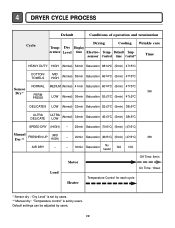
4 DRYER CYCLE PROCESS Cycle Default Conditions of operation and termination Drying Cooling Wrinkle care Temp- Default Tempsensor Control time Control** Time HEAVY DUTY HIGH (Normal) 54min ...
4 DRYER CYCLE PROCESS Cycle Default Conditions of operation and termination Drying Cooling Wrinkle care Temp- Default Tempsensor Control time Control** Time HEAVY DUTY HIGH (Normal) 54min ...

Service Manual
Page 19
LIMIT THERMOSTAT ELECTRIC DRYER WIRING DIAGRAM RLM GAS DRYER WIRING DIAGRAM POWER CORD L1 BLACK RD3 3 2 N WHITE 1 ELECTRONIC CONTROL RED PINK PINK BLUE ORANGE RED BROWN YELLOW BROWN PLC MODEM WHITE BLACK 1 ... DC VALVE1 DC VALVE2 MOISTURE THERMISTOR FLAME SENSOR DETECTOR CENTRIFUGAL SWITCH RED WHITE NC NO GRAY SAFETY THERMOSTAT GAS DRYER WIRING DIAGRAM PLC MODEM RED WHITE BLACK 8 WIRING DIAGRAM 19 RLM ELECTRIC DRYER WIRING DIAGRAM RD3 L1 BLACK 3 2 1 N WHITE 1 2 L2 3 WH3 12 34 BL2 1 2 ELECTRONIC CONTROL RD3 3 2 1 1 2 3 WH3 1 3 56 BROWN BROWN 8 7 6 5 4...
LIMIT THERMOSTAT ELECTRIC DRYER WIRING DIAGRAM RLM GAS DRYER WIRING DIAGRAM POWER CORD L1 BLACK RD3 3 2 N WHITE 1 ELECTRONIC CONTROL RED PINK PINK BLUE ORANGE RED BROWN YELLOW BROWN PLC MODEM WHITE BLACK 1 ... DC VALVE1 DC VALVE2 MOISTURE THERMISTOR FLAME SENSOR DETECTOR CENTRIFUGAL SWITCH RED WHITE NC NO GRAY SAFETY THERMOSTAT GAS DRYER WIRING DIAGRAM PLC MODEM RED WHITE BLACK 8 WIRING DIAGRAM 19 RLM ELECTRIC DRYER WIRING DIAGRAM RD3 L1 BLACK 3 2 1 N WHITE 1 2 L2 3 WH3 12 34 BL2 1 2 ELECTRONIC CONTROL RD3 3 2 1 1 2 3 WH3 1 3 56 BROWN BROWN 8 7 6 5 4...

Service Manual
Page 21
...- Check if Terminal Block and Power Cord are connected (Check Plug ). Does Power Cord N( Natural) line match to Controller. (LED, Display off) Measurement Condition With Dryer Power On; YES NO • Check the fuse or circuit breaker. Check the outlet, is disconnected. N(White) L (Black) L (Led) YES Check if the Controller wire...
...- Check if Terminal Block and Power Cord are connected (Check Plug ). Does Power Cord N( Natural) line match to Controller. (LED, Display off) Measurement Condition With Dryer Power On; YES NO • Check the fuse or circuit breaker. Check the outlet, is disconnected. N(White) L (Black) L (Led) YES Check if the Controller wire...
Service Manual
Page 23
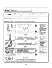
... if Door flame presses door switch knob. • Check Door Switch. • Check Harness connection. " (Brown wire)? No fan will work. Measurement Condition Turn the Dryer's Power Off, then measure resistance. " (White wire) and "BL2- NO YES Does Idle Switch attached to Motor Bracket operate Level by drum belt? NO YES...
... if Door flame presses door switch knob. • Check Door Switch. • Check Harness connection. " (Brown wire)? No fan will work. Measurement Condition Turn the Dryer's Power Off, then measure resistance. " (White wire) and "BL2- NO YES Does Idle Switch attached to Motor Bracket operate Level by drum belt? NO YES...
Service Manual
Page 24
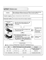
...% ~ Dried clothes 205 ~ 240 Over 4.0V Completely-dried clothes 24 Is the measurement within the range of Table 2 during Diagnostic Test? 2. Measurement Condition Turn the Dryer's Power Off, then measure resistance. linking connector. Is the measurement within the range of Table 2 NO when measuring the voltage in Electric load, is resistance...
...% ~ Dried clothes 205 ~ 240 Over 4.0V Completely-dried clothes 24 Is the measurement within the range of Table 2 during Diagnostic Test? 2. Measurement Condition Turn the Dryer's Power Off, then measure resistance. linking connector. Is the measurement within the range of Table 2 NO when measuring the voltage in Electric load, is resistance...

Service Manual
Page 25
... Component testing.) Check Controller. " (White wire) and "RD3- Check if resistance is not sensed. (Drum motor will flash at 0.5 second intervals.) Measurement Condition After turning Dryer Power Off, measure resistance. Door Close is below 1Ω between "WH3- Check if resistance is below 1Ω between "WH3- " (Yellow wire) and "WH3- Check if...
... Component testing.) Check Controller. " (White wire) and "RD3- Check if resistance is not sensed. (Drum motor will flash at 0.5 second intervals.) Measurement Condition After turning Dryer Power Off, measure resistance. Door Close is below 1Ω between "WH3- Check if resistance is below 1Ω between "WH3- " (Yellow wire) and "WH3- Check if...
Service Manual
Page 27
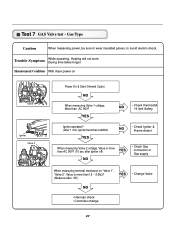
Trouble Symptom While operating, Heating will not work. Measurement Condition With dryer power on "Valve 1", "Valve 2", Value is more than1.5 ~ 2.5kΩ? (Measure after Igniter off) YES NO • Check Gas connection or Gas supply When measuring ...
Trouble Symptom While operating, Heating will not work. Measurement Condition With dryer power on "Valve 1", "Valve 2", Value is more than1.5 ~ 2.5kΩ? (Measure after Igniter off) YES NO • Check Gas connection or Gas supply When measuring ...

Service Manual
Page 34
Detach and remove a knockout at the botton, left or right side as desired. (Right Side Vent not available on Gas dryer) , , the order of work. 1. Pre-assemble 4" elbow with 4" duct. Wrap duct tape around joint. DUCT TAPE 3-2. Reconnect the another duct[11 in(28cm)] to the blower housing, and attach the duct to the internal duct. 34 DUCT TAPE 2-2. Remove a screw and exhaust duct. 2-1. Insert elbow duct assembly first through the side opening and connect the elbow to the base. ( Duct is a SVC part) DUCT TAPE 3-1.
Detach and remove a knockout at the botton, left or right side as desired. (Right Side Vent not available on Gas dryer) , , the order of work. 1. Pre-assemble 4" elbow with 4" duct. Wrap duct tape around joint. DUCT TAPE 3-2. Reconnect the another duct[11 in(28cm)] to the blower housing, and attach the duct to the internal duct. 34 DUCT TAPE 2-2. Remove a screw and exhaust duct. 2-1. Insert elbow duct assembly first through the side opening and connect the elbow to the base. ( Duct is a SVC part) DUCT TAPE 3-1.


