
Service Manual
Page 2
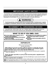
... necessary checks. OR - Touch your building. handle electronic control assembly by individuals possessing adequate backgrounds of all occupants. WARNING ! If electrical power is required for use . ! ESD may result in personal injury and property damage. Connect wrist strap to light a match, or cigarette, or turn on any electrical switches. IMPORTANT SAFETY NOTICE The information in this service guide is intended for diagnosis or test purposes...
... necessary checks. OR - Touch your building. handle electronic control assembly by individuals possessing adequate backgrounds of all occupants. WARNING ! If electrical power is required for use . ! ESD may result in personal injury and property damage. Connect wrist strap to light a match, or cigarette, or turn on any electrical switches. IMPORTANT SAFETY NOTICE The information in this service guide is intended for diagnosis or test purposes...

Service Manual
Page 3
...TEST 7 GAS VALVE TEST - DISASSEMBLY INSTRUCTIONS 30 12. CABINET & DOOR ASSEMBLY 38 12-3-1. DRUM & MOTOR ASSEMBLY : GAS TYPE 40 13. INSTALLATION INSTRUCTIONS 6 4. DIAGNOSTIC TEST ...20 9-1. EXPLODED VIEW ...37 12-1. COMPONENT TESTING INFORMATION 14 6. REPLACEMENT PARTS LIST 41 3 CONTROL LAY - TEST 1 120VAC ELECTRICAL SUPPLY 21 9-2. TEST 2 THERMISTOR TEST --- TEST 3 MOTOR TEST 23 9-4. TEST 6 HEATER SWITCH TEST - GAS TYPE 27 10. CHANGE GAS SETTING (NATURAL GAS, PROPANE GAS 28 11. MEASURE WITH POWER OFF 22 9-3. TEST 4 MOISTURE SENSOR 24 9-5. CONTROL PANEL...
...TEST 7 GAS VALVE TEST - DISASSEMBLY INSTRUCTIONS 30 12. CABINET & DOOR ASSEMBLY 38 12-3-1. DRUM & MOTOR ASSEMBLY : GAS TYPE 40 13. INSTALLATION INSTRUCTIONS 6 4. DIAGNOSTIC TEST ...20 9-1. EXPLODED VIEW ...37 12-1. COMPONENT TESTING INFORMATION 14 6. REPLACEMENT PARTS LIST 41 3 CONTROL LAY - TEST 1 120VAC ELECTRICAL SUPPLY 21 9-2. TEST 2 THERMISTOR TEST --- TEST 3 MOTOR TEST 23 9-4. TEST 6 HEATER SWITCH TEST - GAS TYPE 27 10. CHANGE GAS SETTING (NATURAL GAS, PROPANE GAS 28 11. MEASURE WITH POWER OFF 22 9-3. TEST 4 MOISTURE SENSOR 24 9-5. CONTROL PANEL...

Service Manual
Page 4
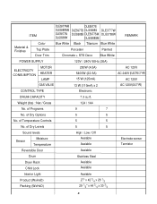
I Weight : 126 (Ibs) Specifications are subject to use. Stacking kit (1 each) Purchased Separately See page 7 for how to use. 4 Pedestal (1 each ) See page 6 for how to change by manufacturer. I Size : 68.6X98.3X76.1 (cm) I ACESSORIES Dryer rack (1 each ) Purchased Separately See page 8 for how to the rating label regarding detailed information. 1 SPECIFICATIONS I Name : Electric and Gas Dryer I Power supply : Please refer to use. I Dryer capacity : IEC 7.3cu.ft.
I Weight : 126 (Ibs) Specifications are subject to use. Stacking kit (1 each) Purchased Separately See page 7 for how to use. 4 Pedestal (1 each ) See page 6 for how to change by manufacturer. I Size : 68.6X98.3X76.1 (cm) I ACESSORIES Dryer rack (1 each ) Purchased Separately See page 8 for how to the rating label regarding detailed information. 1 SPECIFICATIONS I Name : Electric and Gas Dryer I Power supply : Please refer to use. I Dryer capacity : IEC 7.3cu.ft.
Service Manual
Page 5
... 5 5 Sound levels High / Low / Off Sensor Moisture Temperature Avaiable Avaiable Electrode sensor Termistor Reversible Door Avaiable Drum Stainless Steel Dryer Rack Child Lock Avaiable Avaiable Interior Light Product (WxHxD) Packing (WxHxD) Avaiable 27" x 42 3/4 x 28 1/3 29 1/2" x 44 3/4 x 30 3/4 5 Weight (lbs) : Net / Gross 124 / 144 No. of Dry Options 5 5 No. of Programs 9 7 No. ITEM DLE5977WM DLE5977S DLE5988WM DLE5977B DLG5988S DLE3777W DLE5977W DLG5988B DLE5977SM...
... 5 5 Sound levels High / Low / Off Sensor Moisture Temperature Avaiable Avaiable Electrode sensor Termistor Reversible Door Avaiable Drum Stainless Steel Dryer Rack Child Lock Avaiable Avaiable Interior Light Product (WxHxD) Packing (WxHxD) Avaiable 27" x 42 3/4 x 28 1/3 29 1/2" x 44 3/4 x 30 3/4 5 Weight (lbs) : Net / Gross 124 / 144 No. of Dry Options 5 5 No. of Programs 9 7 No. ITEM DLE5977WM DLE5977S DLE5988WM DLE5977B DLG5988S DLE3777W DLE5977W DLG5988B DLE5977SM...
Service Manual
Page 7
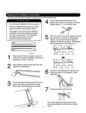
... stacking kit back to the stoppers of side stacking kit. 3 Fit the stacking kit side bracket firmly to the washer with a screw on top of bracket. The weight of the dryer and the height of the front kit. • Do not use stacking kit with one person. Avoid finger injuries - W ARNING Do not attempt installation with a gas dryer in potentially unstable conditions like a mobile home. 7 Stacking Kit Installation Instructions...
... stacking kit back to the stoppers of side stacking kit. 3 Fit the stacking kit side bracket firmly to the washer with a screw on top of bracket. The weight of the dryer and the height of the front kit. • Do not use stacking kit with one person. Avoid finger injuries - W ARNING Do not attempt installation with a gas dryer in potentially unstable conditions like a mobile home. 7 Stacking Kit Installation Instructions...
Service Manual
Page 8
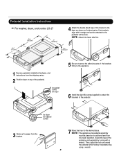
for dryer . Pedestal Installation Instructions For washer, dryer, and combo LG 27 4 Attach the double-faced tape of the bracket to the dryer as shown so the bent parts of the appliance and pedestal by turning with a wrench. for washer/ combo 3 Remove the paper from the shipping carton. 2 Position dryer on a solid and level floor for dryer 5 Be sure to the pedestal. Then, adjust the lock unt toward...
for dryer . Pedestal Installation Instructions For washer, dryer, and combo LG 27 4 Attach the double-faced tape of the bracket to the dryer as shown so the bent parts of the appliance and pedestal by turning with a wrench. for washer/ combo 3 Remove the paper from the shipping carton. 2 Position dryer on a solid and level floor for dryer 5 Be sure to the pedestal. Then, adjust the lock unt toward...
Service Manual
Page 9
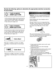
... a fused disconnect or circuit breaker box 5" (12.7 cm) 3-wire direct 31/2" (8.6 cm) If this type is available at this section if your home. d e f c b 9 Review the following options to determine the appropriate electrical connection for dryer to center screw. 4. Connect ground wire(green) of power cord to external ground screw and move neutral ground wire of length in order for your home: 4-wire receptacle (NEMA type14-30R) Use the instructions...
... a fused disconnect or circuit breaker box 5" (12.7 cm) 3-wire direct 31/2" (8.6 cm) If this type is available at this section if your home. d e f c b 9 Review the following options to determine the appropriate electrical connection for dryer to center screw. 4. Connect ground wire(green) of power cord to external ground screw and move neutral ground wire of length in order for your home: 4-wire receptacle (NEMA type14-30R) Use the instructions...

Service Manual
Page 10
... end of the wire under the screw of length in order for cm) dryer to the left and right e terminal block screws. 3. Connect red and black wire to be sure that all terminal block nuts are installing your local codes or ordinances do not allow the use of power cord to the left and right terminal block screws. 3. Prepare minimum 5ft(1.52m) of the terminal block(hooked end facing rightward) and...
... end of the wire under the screw of length in order for cm) dryer to the left and right e terminal block screws. 3. Connect red and black wire to be sure that all terminal block nuts are installing your local codes or ordinances do not allow the use of power cord to the left and right terminal block screws. 3. Prepare minimum 5ft(1.52m) of the terminal block(hooked end facing rightward) and...

Service Manual
Page 12
... when removing the cap. 3. Remove the shipping cap from the gas connection at the factory for checking inlet gas pressure) 3 Equipment Shut-Off Valve-Installed within 6' (1.8 m) of dryer 4 Black Iron Pipe Shorter than 20' (6.1 m) - Pipe Plug (for Natural Gas with a non-corrosive leak detection fluid. 5. Use 1/2" pipe 5 3/8" N.P.T. Connect to gas supply pipe using a new flexible stainless steel connector. 4. 3-2. Turn on Gas Requirements. 1. Make certain your dryer is equipped at the rear of gas in...
... when removing the cap. 3. Remove the shipping cap from the gas connection at the factory for checking inlet gas pressure) 3 Equipment Shut-Off Valve-Installed within 6' (1.8 m) of dryer 4 Black Iron Pipe Shorter than 20' (6.1 m) - Pipe Plug (for Natural Gas with a non-corrosive leak detection fluid. 5. Use 1/2" pipe 5 3/8" N.P.T. Connect to gas supply pipe using a new flexible stainless steel connector. 4. 3-2. Turn on Gas Requirements. 1. Make certain your dryer is equipped at the rear of gas in...
Service Manual
Page 13
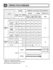
...;C) (5min) (47±5°C) Manual FRESHEN UP Dry ** (MID HIGH) - 20min Saturation (66±5°C) (5min) (47±5°C) 3Hr AIR DRY - - 30min Saturation No heater N/A N/A Load Motor Heater Off Time: 6min On Time: 10sec Temperature Control for each cycle * Sensor dry : "Dry Level" is set by users. ** Manual dry : "Temperature control" is set by users. 13 4 DRYER CYCLE PROCESS Cycle Default Conditions of operation and termination Drying Cooling Wrinkle care Temp- Default settings can be adjusted by users. Dry Display erature Level time Electro- Temp-
...;C) (5min) (47±5°C) Manual FRESHEN UP Dry ** (MID HIGH) - 20min Saturation (66±5°C) (5min) (47±5°C) 3Hr AIR DRY - - 30min Saturation No heater N/A N/A Load Motor Heater Off Time: 6min On Time: 10sec Temperature Control for each cycle * Sensor dry : "Dry Level" is set by users. ** Manual dry : "Temperature control" is set by users. 13 4 DRYER CYCLE PROCESS Cycle Default Conditions of operation and termination Drying Cooling Wrinkle care Temp- Default settings can be adjusted by users. Dry Display erature Level time Electro- Temp-

Service Manual
Page 19
... NO GRAY SAFETY THERMOSTAT GAS DRYER WIRING DIAGRAM PLC MODEM RED WHITE BLACK 8 WIRING DIAGRAM 19 RLM ELECTRIC DRYER WIRING DIAGRAM RD3 L1 BLACK 3 2 1 N WHITE 1 2 L2 3 WH3 12 34 BL2 1 2 ELECTRONIC CONTROL RD3 3 2 1 1 2 3 WH3 1 3 56 BROWN BROWN 8 7 6 5 4 3 2 COM 1 1 2 NO GRAY BL4 LAMP YELLOW 1 2 3 BELT SWITCH YELLOW BLUE BLUE HEATER 21 21 BLUE ORANGE RED NC 123 DOOR SWITCH WHITE 1 2 3 7 10 MOTOR OVERLOAD PROTECTOR MOISTURE THERMISTOR SENSOR RED SAFETY THERMOSTAT...
... NO GRAY SAFETY THERMOSTAT GAS DRYER WIRING DIAGRAM PLC MODEM RED WHITE BLACK 8 WIRING DIAGRAM 19 RLM ELECTRIC DRYER WIRING DIAGRAM RD3 L1 BLACK 3 2 1 N WHITE 1 2 L2 3 WH3 12 34 BL2 1 2 ELECTRONIC CONTROL RD3 3 2 1 1 2 3 WH3 1 3 56 BROWN BROWN 8 7 6 5 4 3 2 COM 1 1 2 NO GRAY BL4 LAMP YELLOW 1 2 3 BELT SWITCH YELLOW BLUE BLUE HEATER 21 21 BLUE ORANGE RED NC 123 DOOR SWITCH WHITE 1 2 3 7 10 MOTOR OVERLOAD PROTECTOR MOISTURE THERMISTOR SENSOR RED SAFETY THERMOSTAT...
Service Manual
Page 20
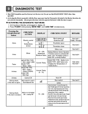
... shut off ) 2. This TEST should be in Standby (unit plugged in normal condition. Unit must be used for Factory test /Service test. Pressing the "START/PAUSE" button CHECKING ACTION DISPLAY CHECKING POINT REMARK None Electric control & Temperature sensor Won't power up Defective LED Thermistor open the door. Buzzer beeps seven times During check, Motor on & Heater If the door is open ) ACTIVATING THE DIAGNOSTIC TEST MODE 1. The display number is open . Press "POWER" while pressing "MORE TIME", and "LESS TIME" simultaneously. 9 DIAGNOSTIC TEST...
... shut off ) 2. This TEST should be in Standby (unit plugged in normal condition. Unit must be used for Factory test /Service test. Pressing the "START/PAUSE" button CHECKING ACTION DISPLAY CHECKING POINT REMARK None Electric control & Temperature sensor Won't power up Defective LED Thermistor open the door. Buzzer beeps seven times During check, Motor on & Heater If the door is open ) ACTIVATING THE DIAGNOSTIC TEST MODE 1. The display number is open . Press "POWER" while pressing "MORE TIME", and "LESS TIME" simultaneously. 9 DIAGNOSTIC TEST...

Service Manual
Page 21
... power, be sure to wear insulated gloves, to Terminal Center N(Natural) line? • Reconnect the controller. Does Power Cord N( Natural) line match to and avoid an electric shock. Check the outlet, is properly connected. N(White) L (Black) L (Led) YES Check if the Controller wire is disconnected. YES NO • Check the fuse or circuit breaker. Check if the voltage measured between Connector "RD3- " (Black) linked to the Controller and "WH3- Check if Terminal Block and Power Cord are connected (Check Plug ). YES Replace...
... power, be sure to wear insulated gloves, to Terminal Center N(Natural) line? • Reconnect the controller. Does Power Cord N( Natural) line match to and avoid an electric shock. Check the outlet, is properly connected. N(White) L (Black) L (Led) YES Check if the Controller wire is disconnected. YES NO • Check the fuse or circuit breaker. Check if the voltage measured between Connector "RD3- " (Black) linked to the Controller and "WH3- Check if Terminal Block and Power Cord are connected (Check Plug ). YES Replace...
Service Manual
Page 22
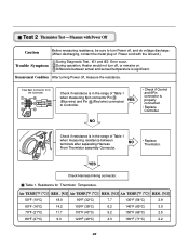
... in the range of Power cord with the Ground.) Trouble Symptom During Diagnostic Test, tE1 and tE2 Error occur. Check if resistance is in the range of Table 1 when measuring 6pin connector Pin (Blue wire) and Pin (Red wire) connected to turn off , measure the resistance. YES Check Harness-linking connector. Difference between terminals after separating Harness NO From Thermistor assembly Connector. • Replace Thermistor. Air TEMP.[°F (°C)] RES...
... in the range of Power cord with the Ground.) Trouble Symptom During Diagnostic Test, tE1 and tE2 Error occur. Check if resistance is in the range of Table 1 when measuring 6pin connector Pin (Blue wire) and Pin (Red wire) connected to turn off , measure the resistance. YES Check Harness-linking connector. Difference between terminals after separating Harness NO From Thermistor assembly Connector. • Replace Thermistor. Air TEMP.[°F (°C)] RES...
Service Manual
Page 23
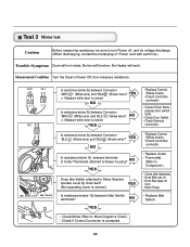
...; Motor Pulley. • Replace Idler Switch. • Check Motor.(Refer to 'Motor Diagram & Check') • Check if Control Connector is closed . " (Brown wire)? NO Is resistance below 3Ω between Connector "WH3- Idler Switch Lever Idler Switch Is resistance below 1Ω between Connector "WH3- YES NO Is resistance below 3Ω between terminals of Power cord with earth line.) Trouble Symptom Drum will work. No Heater will not rotate; No fan will function; Measurement Condition Turn the Dryer's Power...
...; Motor Pulley. • Replace Idler Switch. • Check Motor.(Refer to 'Motor Diagram & Check') • Check if Control Connector is closed . " (Brown wire)? NO Is resistance below 3Ω between Connector "WH3- Idler Switch Lever Idler Switch Is resistance below 1Ω between Connector "WH3- YES NO Is resistance below 3Ω between terminals of Power cord with earth line.) Trouble Symptom Drum will work. No Heater will not rotate; No fan will function; Measurement Condition Turn the Dryer's Power...
Service Manual
Page 24
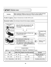
... sure to turn Power off, and do voltage discharge. (When discharging, contact the metal plug of Power cord with earth line.) Trouble Symptom Degree of dryness does not match with metal to 6pin connector's Pin (BLUE wire) and Pin (ORANGE wire) to Electro load: 1. NO YES • Check Electro Load and • Harness Connector. • Check Harness- Damping cloth When contacting cloth to Controller. YES • Replace Control and Check. IMC...
... sure to turn Power off, and do voltage discharge. (When discharging, contact the metal plug of Power cord with earth line.) Trouble Symptom Degree of dryness does not match with metal to 6pin connector's Pin (BLUE wire) and Pin (ORANGE wire) to Electro load: 1. NO YES • Check Electro Load and • Harness Connector. • Check Harness- Damping cloth When contacting cloth to Controller. YES • Replace Control and Check. IMC...

Service Manual
Page 25
...; Door switch Check (Refer to Component testing.) • Check Lamp. (When opening Lamp, replace then measure again.) • Door switch Check(Refer to turn Power off, and do voltage discharge. (When discharging, contact the metal plug of Power cord with earth line.) Door Opening is not sensed.(During operation, when opening Door, Drum motor and Trouble Symptom Heater run continuously; NO • Door switch Check (Refer to Component testing.) Check Controller. Check if resistance is below 1Ω between "WH3- " (White wire) after taking Connector WH3...
...; Door switch Check (Refer to Component testing.) • Check Lamp. (When opening Lamp, replace then measure again.) • Door switch Check(Refer to turn Power off, and do voltage discharge. (When discharging, contact the metal plug of Power cord with earth line.) Door Opening is not sensed.(During operation, when opening Door, Drum motor and Trouble Symptom Heater run continuously; NO • Door switch Check (Refer to Component testing.) Check Controller. Check if resistance is below 1Ω between "WH3- " (White wire) after taking Connector WH3...
Service Manual
Page 26
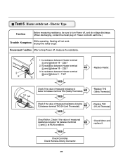
... of measured resistance is below 1Ω between terminal NO and at RUN condition. • Check Motor and replace it. Check Harness-linking Connector. 26 Check if the value of Power cord with earth line.) Trouble Symptom While operating, Heating will not work. YES Check Controller. Is resistance between Heater terminal and below 1Ω between terminal TH2 (Safety Thermostat). Drying time takes longer. Is resistance between Heater terminal and below 18 ~ 22Ω? 2. NO YES...
... of measured resistance is below 1Ω between terminal NO and at RUN condition. • Check Motor and replace it. Check Harness-linking Connector. 26 Check if the value of Power cord with earth line.) Trouble Symptom While operating, Heating will not work. YES Check Controller. Is resistance between Heater terminal and below 1Ω between terminal TH2 (Safety Thermostat). Drying time takes longer. Is resistance between Heater terminal and below 18 ~ 22Ω? 2. NO YES...
Service Manual
Page 27
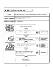
... terminal resistance on Valve 1 Igniter Valve 2 Power On & Start (Normal Cycle) NO When measuring Valve 1 voltage, More than AC 90V? Trouble Symptom While operating, Heating will not work. Drying time takes longer. Measurement Condition With dryer power on "Valve 1", "Valve 2", Value is more than1.5 ~ 2.5kΩ? (Measure after Off ) YES • Change Valve NO • Harness check • Controller change 27 Test 7 GAS Valve test - Gas Type Caution When measuring power, be sure to wear insulated gloves, to avoid electric...
... terminal resistance on Valve 1 Igniter Valve 2 Power On & Start (Normal Cycle) NO When measuring Valve 1 voltage, More than AC 90V? Trouble Symptom While operating, Heating will not work. Drying time takes longer. Measurement Condition With dryer power on "Valve 1", "Valve 2", Value is more than1.5 ~ 2.5kΩ? (Measure after Off ) YES • Change Valve NO • Harness check • Controller change 27 Test 7 GAS Valve test - Gas Type Caution When measuring power, be sure to wear insulated gloves, to avoid electric...
Service Manual
Page 28
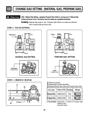
... authorized servicers only. Gas type Orifice P/No Marking Shape Natural Gas 4948EL4001B NCU Propane Gas 4948EL4002B PCU Kit contents : Orifice (Dia. = 1.613mm, for Propane Gas) : Replace Label : Instruction sheet 28 Conversion must be made by a qualified technician. 10 CHANGE GAS SETTING (NATURAL GAS, PROPANE GAS) ! Warning After Natural Gas Setting, applying Propane Gas Orifice or wrong use of Natural Gas Orifice will result in fire. STEP 1 : VALVE SETTING Full open "Change screw" STEP 2 : ORIFICE CHANGE Orifice Close "Change screw" Remove 2 screws. Disassemble the pipe assembly.
... authorized servicers only. Gas type Orifice P/No Marking Shape Natural Gas 4948EL4001B NCU Propane Gas 4948EL4002B PCU Kit contents : Orifice (Dia. = 1.613mm, for Propane Gas) : Replace Label : Instruction sheet 28 Conversion must be made by a qualified technician. 10 CHANGE GAS SETTING (NATURAL GAS, PROPANE GAS) ! Warning After Natural Gas Setting, applying Propane Gas Orifice or wrong use of Natural Gas Orifice will result in fire. STEP 1 : VALVE SETTING Full open "Change screw" STEP 2 : ORIFICE CHANGE Orifice Close "Change screw" Remove 2 screws. Disassemble the pipe assembly.


