
Owners Manual
Page 1
...[ attached on the back cover and quote this manual carefully your dealer when you require service. Environmental Protection Agency(EPA). LOCWD NETRV'S PMLAANSUMAAL TV LCD TV MODELS 32LC7D 37LC7D 42LC7D PLASMA TV MODELS 42PCSD SOPCSD Please read this information to your set . A.,Inc. before operating Record model number and serial number of power-saving...
...[ attached on the back cover and quote this manual carefully your dealer when you require service. Environmental Protection Agency(EPA). LOCWD NETRV'S PMLAANSUMAAL TV LCD TV MODELS 32LC7D 37LC7D 42LC7D PLASMA TV MODELS 42PCSD SOPCSD Please read this information to your set . A.,Inc. before operating Record model number and serial number of power-saving...
Owners Manual
Page 2
... HDMI CEC support of SRS Labs, Inc. under license from SRS Labs, Inc. TruSurround XT technology is a trademark of LG's audio/video device connected to the HDMI (high-definition multimedia interface), LG TV with this logo works easily with one remote control. DIGITAL Manufactured under It has 2 HDMI ports that connect audio and...
... HDMI CEC support of SRS Labs, Inc. under license from SRS Labs, Inc. TruSurround XT technology is a trademark of LG's audio/video device connected to the HDMI (high-definition multimedia interface), LG TV with this logo works easily with one remote control. DIGITAL Manufactured under It has 2 HDMI ports that connect audio and...

Owners Manual
Page 3
...the equipment and receiver. - Connect the equipment to an outlet on , the user is connected. -Consult the dealer or an experienced radio/TV technician for proper grounding and, in a particular installation. The code provides guidelines for help. These limits are designed to operate the equipment. ... reception, which the receiver is encouraged to try to correct the interference by turning the equipment off and on a circuit different from LG Electronics. Do not attempt to rain or moisture. Class B digital device This equipment has been tested and found to comply with the...
...the equipment and receiver. - Connect the equipment to an outlet on , the user is connected. -Consult the dealer or an experienced radio/TV technician for proper grounding and, in a particular installation. The code provides guidelines for help. These limits are designed to operate the equipment. ... reception, which the receiver is encouraged to try to correct the interference by turning the equipment off and on a circuit different from LG Electronics. Do not attempt to rain or moisture. Class B digital device This equipment has been tested and found to comply with the...
Owners Manual
Page 6
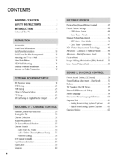
... Preset Picture Settings 44 - Preset 45 Manual Picture Adjustment 46 - i_i_i_i_i_iC_ai_pi_tiio_ni_iO_ip_tii_oin_i_i_..i._..J..i_..i 63 Remote Control Key Functions 30 Turning On TV 32 Channel Selection 32 Volume Adjustment 52 On-Screen Menus Selection 33 Channel Search 34 - Cinema 5:2 Pulldown Mode 49 Advanced -... Setup 58 Audio Language 59 On-Screen Menus Language Selection 60 Caption/Text 61 - Preset 44 - Black (Darkness) Level 50 Picture Reset 51 Image Sticking Minimization (ISM) Method ....... 52 Low - User Mode 46 - Channel Editing 36 DTV Signal ...
... Preset Picture Settings 44 - Preset 45 Manual Picture Adjustment 46 - i_i_i_i_i_iC_ai_pi_tiio_ni_iO_ip_tii_oin_i_i_..i._..J..i_..i 63 Remote Control Key Functions 30 Turning On TV 32 Channel Selection 32 Volume Adjustment 52 On-Screen Menus Selection 33 Channel Search 34 - Cinema 5:2 Pulldown Mode 49 Advanced -... Setup 58 Audio Language 59 On-Screen Menus Language Selection 60 Caption/Text 61 - Preset 44 - Black (Darkness) Level 50 Picture Reset 51 Image Sticking Minimization (ISM) Method ....... 52 Low - User Mode 46 - Channel Editing 36 DTV Signal ...

Owners Manual
Page 7
SleepTimerSetting 6..7... Set Password 70 - AutoShut-ofSf etting 6..8.... Lock System 70 Channel Blocking 71 External Input Blocking 71 Movie & TV Rating 72 - TV Rating English & French (forCanada only) .. 74 Troubleshooting 75 Maintenance 77 Product Specifications 78 Programming the Remote Control 80 IR Codes... 86 S AutoClockSetup 6..4... - Set Password & Lock System 69 - Setting up Your Password 69 - AutoOn/OffTimerSetting 6..6.. Movie Rating (MPAA 72 - ClockSetting 6..4..... - TV Rating Children & General (forUSAonly) 73 - ManuaCl lockSetup 6..5...
SleepTimerSetting 6..7... Set Password 70 - AutoShut-ofSf etting 6..8.... Lock System 70 Channel Blocking 71 External Input Blocking 71 Movie & TV Rating 72 - TV Rating English & French (forCanada only) .. 74 Troubleshooting 75 Maintenance 77 Product Specifications 78 Programming the Remote Control 80 IR Codes... 86 S AutoClockSetup 6..4... - Set Password & Lock System 69 - Setting up Your Password 69 - AutoOn/OffTimerSetting 6..6.. Movie Rating (MPAA 72 - ClockSetting 6..4..... - TV Rating Children & General (forUSAonly) 73 - ManuaCl lockSetup 6..5...
Owners Manual
Page 8
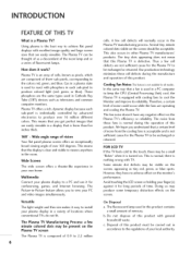
...PC and video images simultaneously. Our production technology minimizes these fans is normal during the manufacture and operation of this Plasma TV is used in the Plasma TV manufacturing process. Versatile The light weight and thin size makes it easy to be present on the screen, appearing as... and is fewer than five inches thick. 160 ° - Avoid touching the LCD screen or holdingyour finger(s) against it work? The Plasma TV can be carried out in a display that a certain level of noise from these cell defects during the operation of this product contains a...
...PC and video images simultaneously. Our production technology minimizes these fans is normal during the manufacture and operation of this Plasma TV is used in the Plasma TV manufacturing process. Versatile The light weight and thin size makes it easy to be present on the screen, appearing as... and is fewer than five inches thick. 160 ° - Avoid touching the LCD screen or holdingyour finger(s) against it work? The Plasma TV can be carried out in a display that a certain level of noise from these cell defects during the operation of this product contains a...

Owners Manual
Page 9
...Manual CD Manual Remote Control, Batteries Power Cord 75ohm Round Cable Polishing Cloth * Slightly wipe stained spot on the exterior only with your product. TV Brackets, (Refer to p.14) Cable Management Twist Holder Arrange the wires with the twist holder. 7 PREPARATION ACCESSORIES Ensure that excessive pressure may ...cause scratch or discoloration. 2-Eye-bolts (Refer to p.14) 2-Wall brackets (Refer to p.14) D-sub 15 pin Cable 2- TV Bracket Bolts 2- Please be cautions of the exterior. * Do not wipe roughly when removing stain. Wall Brackets (Refer to p.14) 2-
...Manual CD Manual Remote Control, Batteries Power Cord 75ohm Round Cable Polishing Cloth * Slightly wipe stained spot on the exterior only with your product. TV Brackets, (Refer to p.14) Cable Management Twist Holder Arrange the wires with the twist holder. 7 PREPARATION ACCESSORIES Ensure that excessive pressure may ...cause scratch or discoloration. 2-Eye-bolts (Refer to p.14) 2-Wall brackets (Refer to p.14) D-sub 15 pin Cable 2- TV Bracket Bolts 2- Please be cautions of the exterior. * Do not wipe roughly when removing stain. Wall Brackets (Refer to p.14) 2-

Owners Manual
Page 10
PREPARATION FRONT PANELINFORMATION _ Here shown may be somewhat different from your TV. _D I-rl Front Panel Controls z Plasma TV Model Remote Control Sensor Power Standby Indicator Illuminates red in standby mode. l(_ ,A)Buttons 8 When the TV is turned on, the indicator blinks green and then illuminates green before the picture is displayed.
PREPARATION FRONT PANELINFORMATION _ Here shown may be somewhat different from your TV. _D I-rl Front Panel Controls z Plasma TV Model Remote Control Sensor Power Standby Indicator Illuminates red in standby mode. l(_ ,A)Buttons 8 When the TV is turned on, the indicator blinks green and then illuminates green before the picture is displayed.

Owners Manual
Page 11
When the TV is turned on, the indicator blinks green and then illuminates green before the picture is displayed. 9 LCD TV Model _D z (A,Y)Bu_ons (_,_)Bu_ons Bu_on Bu_on Bu_on Bu_on Power Standby Indicator Illuminates red in standby mode.
When the TV is turned on, the indicator blinks green and then illuminates green before the picture is displayed. 9 LCD TV Model _D z (A,Y)Bu_ons (_,_)Bu_ons Bu_on Bu_on Bu_on Bu_on Power Standby Indicator Illuminates red in standby mode.

Owners Manual
Page 12
PREPARATION BACK PANELINFORMATION _ Here shown may be somewhat different from your TV. Back Connection Panel Ffl Plasma TV Model z LCD TV Model lO
PREPARATION BACK PANELINFORMATION _ Here shown may be somewhat different from your TV. Back Connection Panel Ffl Plasma TV Model z LCD TV Model lO

Owners Manual
Page 13
.... AUDIO IN (RGB/DVI) Connect the audio from a PC. _o @ COMPONENT IN Power Cord Socket Connect a component video/audio device to operate the TV on DC power. z Connect a second TV or monitor. _AV (Audio/Video) IN 2 @ AV (Audio/Video) IN 1 Connect audio/video output device to these For operation with AC power...
.... AUDIO IN (RGB/DVI) Connect the audio from a PC. _o @ COMPONENT IN Power Cord Socket Connect a component video/audio device to operate the TV on DC power. z Connect a second TV or monitor. _AV (Audio/Video) IN 2 @ AV (Audio/Video) IN 1 Connect audio/video output device to these For operation with AC power...

Owners Manual
Page 14
Plasma TV Model m Hold the CABLE MANAGEMENT with both hands and pull it backward as shown. 12 To connect an additional equipment, see the EXTERNAL EQUIPMENT SETUP section. O Install the CABLE MANAGEMENT as shown. z CABLE MANAGEMENT Connect the cables as necessary. PREPARATION BACK COVER FOR WIRE ARRANGEMENT I Here shown may be somewhat different from your TV.
Plasma TV Model m Hold the CABLE MANAGEMENT with both hands and pull it backward as shown. 12 To connect an additional equipment, see the EXTERNAL EQUIPMENT SETUP section. O Install the CABLE MANAGEMENT as shown. z CABLE MANAGEMENT Connect the cables as necessary. PREPARATION BACK COVER FOR WIRE ARRANGEMENT I Here shown may be somewhat different from your TV.

Owners Manual
Page 15
O Install the CABLE MANAGEMENT as necessary. LCD TV Model Connect the cables as shown. To connect an additional equipment, see the EXTERNAL EQUIPMENT SETUP section. Bundle the cables using the supplied twist holder. _o m _o z CABLE MANAGEMENT 13
O Install the CABLE MANAGEMENT as necessary. LCD TV Model Connect the cables as shown. To connect an additional equipment, see the EXTERNAL EQUIPMENT SETUP section. Bundle the cables using the supplied twist holder. _o m _o z CABLE MANAGEMENT 13

Owners Manual
Page 16
... A WALL I Here shown may be somewhat different from the TV. Plasma TV Model LCD TV Model z ..l_Insert the eye-bolts (or TV brackets and bolts) to tighten the product to the wall as parts of...product. 14 Use a sturdy rope (not provided as parts of the bracket that you set up the TV close to tie the rope so it cannot fall over if pushed backwards. It is mounted on or ... we recommend that children don't climb on the wall to the wall. Caution: Please make sure that the TV be pulled in the eye-bolts position before inserting the eye-bolts, loosen the bolts. Match the height of...
... A WALL I Here shown may be somewhat different from the TV. Plasma TV Model LCD TV Model z ..l_Insert the eye-bolts (or TV brackets and bolts) to tighten the product to the wall as parts of...product. 14 Use a sturdy rope (not provided as parts of the bracket that you set up the TV close to tie the rope so it cannot fall over if pushed backwards. It is mounted on or ... we recommend that children don't climb on the wall to the wall. Caution: Please make sure that the TV be pulled in the eye-bolts position before inserting the eye-bolts, loosen the bolts. Match the height of...

Owners Manual
Page 18
Plasma TV Model LCD TV Model 4 inches I 4 inches 4 inches 4 inches 4 inches I 4 inches 4 inches 4 inches 16 PREPARATION VESAWALL MOUNTING This product accepts a VESA-compliant mounting interface pad. (optional) There 4 threaded holes are available for attaching the bracket. _o m Plasma TV Model _o 600 mm Z LCD TV Model 600 mm (32 inches only: 200 mm) 400 mm 400 mm (32 inches only: 100 mm) DESKTOP PEDESTALINSTALLATION For proper ventilation, allow a clearance of 4inches on all four sides from the wall.
Plasma TV Model LCD TV Model 4 inches I 4 inches 4 inches 4 inches 4 inches I 4 inches 4 inches 4 inches 16 PREPARATION VESAWALL MOUNTING This product accepts a VESA-compliant mounting interface pad. (optional) There 4 threaded holes are available for attaching the bracket. _o m Plasma TV Model _o 600 mm Z LCD TV Model 600 mm (32 inches only: 200 mm) 400 mm 400 mm (32 inches only: 100 mm) DESKTOP PEDESTALINSTALLATION For proper ventilation, allow a clearance of 4inches on all four sides from the wall.

Owners Manual
Page 19
and install properly. Using both cable and antenna •Antenn RF Coaxial Wire (75 ohm) Cable TV _ Wall Jack RF Coaxial Wire (75 ohm) y-ry_ Diplexer (Signal Combiner) Antenna VHF ,,l_To improve the picture quality in a poor signal area, please purchase a... a Cable Box m Connections. 7> For optimum picture quality, adjust antenna direction if needed. z (VHF, UHF) I Single-family Dwellings/Houses E (Connect to be split for two TV's, install a 2-Way Signal Splitter. ,_ If the antenna is not installed properly, contact your dealer for outdoor antenna) _; 2. Cable Cable...
and install properly. Using both cable and antenna •Antenn RF Coaxial Wire (75 ohm) Cable TV _ Wall Jack RF Coaxial Wire (75 ohm) y-ry_ Diplexer (Signal Combiner) Antenna VHF ,,l_To improve the picture quality in a poor signal area, please purchase a... a Cable Box m Connections. 7> For optimum picture quality, adjust antenna direction if needed. z (VHF, UHF) I Single-family Dwellings/Houses E (Connect to be split for two TV's, install a 2-Way Signal Splitter. ,_ If the antenna is not installed properly, contact your dealer for outdoor antenna) _; 2. Cable Cable...
Owners Manual
Page 20
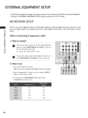
...refer to the figure as shown m x below. Match the jack colors c (Y = green, PB = blue, and PR = red). HD RECEIVERSETUP This TV can receive Digital Over-the-air/Cable signals without an external digital set -top box. This part of the digital set z top box to the... m Connect the video outputs (Y, PB, PR) of EXTERNAL EQUIPMENT SETUP mainly use Turn on the remote control. How to the owner's manual for LCD TV model. operation) Select Component 1 input source by using the INPUT button on the digital set . 2. II"1 z When connecting Component cable m _0 c...
...refer to the figure as shown m x below. Match the jack colors c (Y = green, PB = blue, and PR = red). HD RECEIVERSETUP This TV can receive Digital Over-the-air/Cable signals without an external digital set -top box. This part of the digital set z top box to the... m Connect the video outputs (Y, PB, PR) of EXTERNAL EQUIPMENT SETUP mainly use Turn on the remote control. How to the owner's manual for LCD TV model. operation) Select Component 1 input source by using the INPUT button on the digital set . 2. II"1 z When connecting Component cable m _0 c...
Owners Manual
Page 23
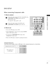
... to the component input ports as shown below. m Select Component I input source by using the INPUT button on DVD player 21 Component ports on the TV Y P_ iilii+++i+l+p++'+'+'+?'++l+++?+l+++?+l+++?+l+++?+l+++?+ii Video output ports on the remote control.
... to the component input ports as shown below. m Select Component I input source by using the INPUT button on DVD player 21 Component ports on the TV Y P_ iilii+++i+l+p++'+'+'+?'++l+++?+l+++?+l+++?+l+++?+l+++?+ii Video output ports on the remote control.
Owners Manual
Page 25
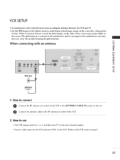
VCR SETUP ,,i_To avoid picture noise (interference), leave an adequate distance between the VCR and TV. ,,i_Use the ISM feature in the Option menu to avoid having a fixed image remain on the screen for a long period of the VCR. How to ... used; Insert a video tape into the VCR and press PLAY on the screen. How to use Set VCR output switch to 3 or 4 and then tune TV to all manufactures and in socket of time. t-m x When connecting with an antenna m _o z r'_ c m z c Wall Jack 1. the fixed images on the sides of the screen...
VCR SETUP ,,i_To avoid picture noise (interference), leave an adequate distance between the VCR and TV. ,,i_Use the ISM feature in the Option menu to avoid having a fixed image remain on the screen for a long period of the VCR. How to ... used; Insert a video tape into the VCR and press PLAY on the screen. How to use Set VCR output switch to 3 or 4 and then tune TV to all manufactures and in socket of time. t-m x When connecting with an antenna m _o z r'_ c m z c Wall Jack 1. the fixed images on the sides of the screen...

Owners Manual
Page 26
... 1. How to use Insert a video tape into the VCR and press PLAY on the set . 2. If connected to connect Connect the AUDIO/VIDEO jacks between TV and VCR. EXTERNAL EQUIPMENT SETUP When connecting with an S-Video cable I. How to AV IN2, select AV2 input source. 24 How to connect Connect the...
... 1. How to use Insert a video tape into the VCR and press PLAY on the set . 2. If connected to connect Connect the AUDIO/VIDEO jacks between TV and VCR. EXTERNAL EQUIPMENT SETUP When connecting with an S-Video cable I. How to AV IN2, select AV2 input source. 24 How to connect Connect the...


