
Owner's Manual (English)
Page 1
LCD TV MODELS 32LB9D* 42LB9DF* 47LB9DF* 52LB9DF* PLASMA TV MODELS 50PY3DF* 60PY3DF* 42PB4D* 50PB4D* DVB is a registered trademark of the DVB Project ID Number: 4757: 32LB9D 4756: 42LB9DF 4755: 47LB9DF 4754: 52LB9DF 4709: 50PY3DF 4708: 60PY3DF 4836: 42PB4D 4837: 50PB4D O N L Y :42LB9DF 47LB9DF 52LB9DF 50PY3DF 60PY3DF
LCD TV MODELS 32LB9D* 42LB9DF* 47LB9DF* 52LB9DF* PLASMA TV MODELS 50PY3DF* 60PY3DF* 42PB4D* 50PB4D* DVB is a registered trademark of the DVB Project ID Number: 4757: 32LB9D 4756: 42LB9DF 4755: 47LB9DF 4754: 52LB9DF 4709: 50PY3DF 4708: 60PY3DF 4836: 42PB4D 4837: 50PB4D O N L Y :42LB9DF 47LB9DF 52LB9DF 50PY3DF 60PY3DF

Owner's Manual (English)
Page 3
... p. 16 42/50PB4D* only This feature is missing, please con- INPUT D/A INPUT POWER SIMPLINK BRIGHT MODE TV VCR DVD RATIO TEXT INFO i GUIDE Owner's Manual 1.5V 1.5V Batteries MENU EXIT SUBTITLE MARK OK VOL Q.VIEW PR PAGE MUTE 1 2 3 4 5 6 7 8 9 LIST 0 FAV SIZE ? For LCD TV models I /II...product exterior if there is not available for all models. 2- If an accessory is not available for all models. 32LB9D* only Cable Management 50/60PY3DF* only Twist Holder Arrange the wires with your product. Bolts Refer to p. 16 3 - Wall Brackets 1 I Do not wipe ...
... p. 16 42/50PB4D* only This feature is missing, please con- INPUT D/A INPUT POWER SIMPLINK BRIGHT MODE TV VCR DVD RATIO TEXT INFO i GUIDE Owner's Manual 1.5V 1.5V Batteries MENU EXIT SUBTITLE MARK OK VOL Q.VIEW PR PAGE MUTE 1 2 3 4 5 6 7 8 9 LIST 0 FAV SIZE ? For LCD TV models I /II...product exterior if there is not available for all models. 2- If an accessory is not available for all models. 32LB9D* only Cable Management 50/60PY3DF* only Twist Holder Arrange the wires with your product. Bolts Refer to p. 16 3 - Wall Brackets 1 I Do not wipe ...
Owner's Manual (English)
Page 4
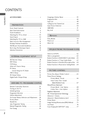
...71 Advanced - Picture Mode - CONTENTS CONTENTS ACCESSORIES 1 PREPARATION i Front Panel Controls 4 Back Panel Information 6 Stand Installation 9 Attaching the TV to a Desk 10 Swivel Stand 10 Attaching the TV to a Wall 11 Back Cover for PC Mode 29 USB In Setup 31 AV Output Setup 32 Digital Audio Output Setup... 42 Fine Tuning 44 Assigning a Station Name 45 Programme Edit 46 Input List 48 Calling Up the Channel List 49 Input Source Selection 50 SIMPLINK 51 Key Lock 53 Entry Modes 54 Photo List 55 Music List 59 EPG(ELECTRONIC PROGRAMME GUIDE) Switch on/off EPG 62 Select...
...71 Advanced - Picture Mode - CONTENTS CONTENTS ACCESSORIES 1 PREPARATION i Front Panel Controls 4 Back Panel Information 6 Stand Installation 9 Attaching the TV to a Desk 10 Swivel Stand 10 Attaching the TV to a Wall 11 Back Cover for PC Mode 29 USB In Setup 31 AV Output Setup 32 Digital Audio Output Setup... 42 Fine Tuning 44 Assigning a Station Name 45 Programme Edit 46 Input List 48 Calling Up the Channel List 49 Input Source Selection 50 SIMPLINK 51 Key Lock 53 Entry Modes 54 Photo List 55 Music List 59 EPG(ELECTRONIC PROGRAMME GUIDE) Switch on/off EPG 62 Select...

Owner's Manual (English)
Page 5
... 96 TOP Text 96 Fastext 97 Special Teletext Functions 97 After reading this manual, keep it handy for future reference. 3 User Mode 80 Balance 82 TV Speakers On/ Off Setup 83 I/II - CONTENTS SOUND & LANGUAGE CONTROL Auto Volume Leveler ( Auto Volume 78 Preset Sound Settings-
... 96 TOP Text 96 Fastext 97 Special Teletext Functions 97 After reading this manual, keep it handy for future reference. 3 User Mode 80 Balance 82 TV Speakers On/ Off Setup 83 I/II - CONTENTS SOUND & LANGUAGE CONTROL Auto Volume Leveler ( Auto Volume 78 Preset Sound Settings-

Owner's Manual (English)
Page 6
PREPARATION FRONT PANEL CONTROLS I If your TV. Image shown may be somewhat different from your product has a protection film attached, remove the film and then wipe the product with a polishing cloth. 50/60PY3DF* PREPARATION Remote Control Sensor Program Display INPUT MENU OK Touch Pad VOL OK PR PR Power Standby Indicator • illuminates...
PREPARATION FRONT PANEL CONTROLS I If your TV. Image shown may be somewhat different from your product has a protection film attached, remove the film and then wipe the product with a polishing cloth. 50/60PY3DF* PREPARATION Remote Control Sensor Program Display INPUT MENU OK Touch Pad VOL OK PR PR Power Standby Indicator • illuminates...

Owner's Manual (English)
Page 9
...this port with AC power. RGB IN HDMI/DVI IN 3 RS-232C IN (CONTROL &SERVICE)RPGBO(PRC)T AUDIO (RGB/DVI) Connect to operate the TV on a PC. AUDIO S-VIDEO VIDEO ( ) AUDIO 6 DIGITAL AUDIO OUT Connect digital audio from an S-VIDEO device. Connect a component video/audio device... ports do not work. 7 AUDIO OUT REMOTE CONTROL IN OPTICAL VIDEO 9 AV OUT AV OUT 4 Remote Control Port COMPONENT IN ConRnS-2e32cCtINa second TV or monitor. (CONTROL & SERVICE) Connect your wired remote control. 10 Power Cord Socket 5 ANTENNA IN Connect antenna signals to the appropriate input port...
...this port with AC power. RGB IN HDMI/DVI IN 3 RS-232C IN (CONTROL &SERVICE)RPGBO(PRC)T AUDIO (RGB/DVI) Connect to operate the TV on a PC. AUDIO S-VIDEO VIDEO ( ) AUDIO 6 DIGITAL AUDIO OUT Connect digital audio from an S-VIDEO device. Connect a component video/audio device... ports do not work. 7 AUDIO OUT REMOTE CONTROL IN OPTICAL VIDEO 9 AV OUT AV OUT 4 Remote Control Port COMPONENT IN ConRnS-2e32cCtINa second TV or monitor. (CONTROL & SERVICE) Connect your wired remote control. 10 Power Cord Socket 5 ANTENNA IN Connect antenna signals to the appropriate input port...

Owner's Manual (English)
Page 10
...Or DVI(VIDEO) signal to the this jack. device to these ports do not work. Never attemDIGpITtALto AUDIO OUT operate the TV on a PC. 9 AV OUT 4 Remote Control Port Connect a second TV or monitor. VIDEO L/MONO AUDIO R VIDEO L/MONO AUDIO R USB IN VIDEO L/MONO AUDIO R VIDEO L/MONO AUDIO R ...different from your wired remote control. 10 Power Cord Socket 5 ANTENNA IN HDMI/DVI IN Connect antenna signals to this port with AACNTEpNoNwAer. LCD TV Models 42/47/52LB9DF* USB IN S-VIDEO USB IN 32LB9D* USB IN S-VIDEO USB Input S-VIDEO Input Connect S-Video out from an S-...
...Or DVI(VIDEO) signal to the this jack. device to these ports do not work. Never attemDIGpITtALto AUDIO OUT operate the TV on a PC. 9 AV OUT 4 Remote Control Port Connect a second TV or monitor. VIDEO L/MONO AUDIO R VIDEO L/MONO AUDIO R USB IN VIDEO L/MONO AUDIO R VIDEO L/MONO AUDIO R ...different from your wired remote control. 10 Power Cord Socket 5 ANTENNA IN HDMI/DVI IN Connect antenna signals to this port with AACNTEpNoNwAer. LCD TV Models 42/47/52LB9DF* USB IN S-VIDEO USB IN 32LB9D* USB IN S-VIDEO USB Input S-VIDEO Input Connect S-Video out from an S-...
Owner's Manual (English)
Page 12
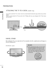
... injury. 1-screw Stand Desk SWIVEL STAND After installing the TV, you can adjust the the TV set the hole. 10 PREPARATION PREPARATION ATTACHING THE TV TO A DESK (32LB9D* Only) If you wish to attach the TV to a desk, it must be level with TV, you must remove the cable management and loosen (to... set manually to the left or right direction by 20 degrees to suit your viewing position. 50/60PY3DF* models NOTE G Before adjusting the angle, you must...
... injury. 1-screw Stand Desk SWIVEL STAND After installing the TV, you can adjust the the TV set the hole. 10 PREPARATION PREPARATION ATTACHING THE TV TO A DESK (32LB9D* Only) If you wish to attach the TV to a desk, it must be level with TV, you must remove the cable management and loosen (to... set manually to the left or right direction by 20 degrees to suit your viewing position. 50/60PY3DF* models NOTE G Before adjusting the angle, you must...

Owner's Manual (English)
Page 13
... product. ! It is safer to the wall so the product doesn't fall . G Use a product holder or a cabinet that of the product. 11 PREPARATION ATTACHING THE TV TO A WALL A This Feature is not available for the size and weight of the product. A Set it up the product, which is to fix it... on or hang from the product. 60PY3DF* 1 50PY3DF* 1 2 42/50PB4D* 1 2 42/47/52LB9DF*, 32LB9D* 1 2 2 1 Use the eye-bolts or TV brackets/bolts to fix the product to the wall as shown in the picture. (If your product has the bolts in...
... product. ! It is safer to the wall so the product doesn't fall . G Use a product holder or a cabinet that of the product. 11 PREPARATION ATTACHING THE TV TO A WALL A This Feature is not available for the size and weight of the product. A Set it up the product, which is to fix it... on or hang from the product. 60PY3DF* 1 50PY3DF* 1 2 42/50PB4D* 1 2 42/47/52LB9DF*, 32LB9D* 1 2 2 1 Use the eye-bolts or TV brackets/bolts to fix the product to the wall as shown in the picture. (If your product has the bolts in...

Owner's Manual (English)
Page 14
PREPARATION PREPARATION BACK COVER FOR WIRE ARRANGEMENT I Here shown may be somewhat different from your TV. 50/60PY3DF* 1 Hold the CABLE MANAGEMENT with both hands and pull it as shown. 45° CABLE MANAGEMENT 2 Connect the cables as shown. 12 To connect additional equipment, see the External equipment Setup section. 3 Install the CABLE MANAGEMENT as necessary.
PREPARATION PREPARATION BACK COVER FOR WIRE ARRANGEMENT I Here shown may be somewhat different from your TV. 50/60PY3DF* 1 Hold the CABLE MANAGEMENT with both hands and pull it as shown. 45° CABLE MANAGEMENT 2 Connect the cables as shown. 12 To connect additional equipment, see the External equipment Setup section. 3 Install the CABLE MANAGEMENT as necessary.

Owner's Manual (English)
Page 19
... Box Connections. For optimum picture quality, adjust antenna direction if needed. I If the antenna is not installed properly, contact your dealer for two TV's, install a 2-Way Signal Splitter. PREPARATION I To prevent the equipment damage, never plug in a poor signal area, please purchase a signal amplifier... and install properly. NOTE G The TV will let you have finished connecting all equipment. I To improve the picture quality in any power cords until you know when the analogue, ...
... Box Connections. For optimum picture quality, adjust antenna direction if needed. I If the antenna is not installed properly, contact your dealer for two TV's, install a 2-Way Signal Splitter. PREPARATION I To prevent the equipment damage, never plug in a poor signal area, please purchase a signal amplifier... and install properly. NOTE G The TV will let you have finished connecting all equipment. I To improve the picture quality in any power cords until you know when the analogue, ...
Owner's Manual (English)
Page 20
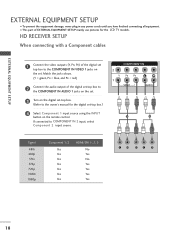
... the digital set -top box.) 4 Select Component 1 input source using the INPUT button on the set. If connected to the owner's manual for the LCD TV models. EXTERNAL EQUIPMENT SETUP EXTERNAL EQUIPMENT SETUP I This part of EXTERNAL EQUIPMENT SETUP mainly use pictures for the digital set -top box. (Refer to COMPONENT...
... the digital set -top box.) 4 Select Component 1 input source using the INPUT button on the set. If connected to the owner's manual for the LCD TV models. EXTERNAL EQUIPMENT SETUP EXTERNAL EQUIPMENT SETUP I This part of EXTERNAL EQUIPMENT SETUP mainly use pictures for the digital set -top box. (Refer to COMPONENT...

Owner's Manual (English)
Page 23
... the set . 3 Turn on the DVD player, insert a DVD. 4 Select Component 1 input source using the INPUT button on the remote control. Component ports on the TV Y PB PR Video output ports on the set . DVD SETUP When connecting Component cables 1 Connect the video outputs (Y, PB, PR) of the DVD to the...
... the set . 3 Turn on the DVD player, insert a DVD. 4 Select Component 1 input source using the INPUT button on the remote control. Component ports on the TV Y PB PR Video output ports on the set . DVD SETUP When connecting Component cables 1 Connect the video outputs (Y, PB, PR) of the DVD to the...

Owner's Manual (English)
Page 25
... owner's manual.) 23 I N socket on the screen. the fixed images on the sides of the VCR. 3 Set VCR output switch to 3 or 4 and then tune TV to the same programme number. 4 Insert a video tape into the VCR and press PLAY on the VCR. (Refer to the RF antenna in consequence the... phenomenon. 2 1 (DVI) COMPONENT IN VIDEO AUDIO VIDEO ( ) AUDIO AV IN 1 VCR SETUP I To avoid picture noise (interference), leave an adequate distance between the VCR and TV.
... owner's manual.) 23 I N socket on the screen. the fixed images on the sides of the VCR. 3 Set VCR output switch to 3 or 4 and then tune TV to the same programme number. 4 Insert a video tape into the VCR and press PLAY on the VCR. (Refer to the RF antenna in consequence the... phenomenon. 2 1 (DVI) COMPONENT IN VIDEO AUDIO VIDEO ( ) AUDIO AV IN 1 VCR SETUP I To avoid picture noise (interference), leave an adequate distance between the VCR and TV.

Owner's Manual (English)
Page 26
... AUDIO 1 Connect the S-VIDEO output of the set. COMPONENT IN 2 When connecting with an RCA cable 1 (DVI) VIDEO AUDIO 1 Connect the AUDIO/VIDEO jacks between TV and VCR. ANTENNA 1 2 RGB IN IN 3 HDMI/DVI IN InsReGrBt(PaC)video tape into the VCR and press PLAY on the VCR. (Refer to the...
... AUDIO 1 Connect the S-VIDEO output of the set. COMPONENT IN 2 When connecting with an RCA cable 1 (DVI) VIDEO AUDIO 1 Connect the AUDIO/VIDEO jacks between TV and VCR. ANTENNA 1 2 RGB IN IN 3 HDMI/DVI IN InsReGrBt(PaC)video tape into the VCR and press PLAY on the VCR. (Refer to the...

Owner's Manual (English)
Page 27
Match the jack colours.(Video = yellow, Audio Left = white, and Audio Right = red) 2 Select AV2 input source using the INPUT button on the remote control. If connected to AV IN1 input, select AV1 input source. 3 Operate the corresponding external equipment. 25 EXTERNAL EQUIPMENT SETUP OTHER A/V SOURCE SETUP 32 inches 42/47/50/52/60 inches USB IN USB IN VIDEO L/MONO AUDIO R 1 AV IN 2 VIDEO L/MONO AUDIO R S-VIDEO 1 AV IN 2 VIDEO L R Camcorder Video Game Set VIDEO L R Camcorder Video Game Set 1 Connect the AUDIO/VIDEO jacks between TV and external equipment.
Match the jack colours.(Video = yellow, Audio Left = white, and Audio Right = red) 2 Select AV2 input source using the INPUT button on the remote control. If connected to AV IN1 input, select AV1 input source. 3 Operate the corresponding external equipment. 25 EXTERNAL EQUIPMENT SETUP OTHER A/V SOURCE SETUP 32 inches 42/47/50/52/60 inches USB IN USB IN VIDEO L/MONO AUDIO R 1 AV IN 2 VIDEO L/MONO AUDIO R S-VIDEO 1 AV IN 2 VIDEO L R Camcorder Video Game Set VIDEO L R Camcorder Video Game Set 1 Connect the AUDIO/VIDEO jacks between TV and external equipment.

Owner's Manual (English)
Page 28
.... There may be changed, change the PC graphic card or consult the manufacturer of Special menu. 5 Once you select RGB-PC in PC mode. The TV perceives 1024x768, 60Hz as DTV 720p based on the PC and the set. 4 Select RGB-PC input source in input option of the PC graphic... the PC graphic card can not be noise associated with the resolution, vertical pattern, contrast or brightness in input option of the PC to the TV's settings. If noise is present, change the PC output to the AUDIO (RGB/DVI) jack on the VIDEO menu until the picture is also available...
.... There may be changed, change the PC graphic card or consult the manufacturer of Special menu. 5 Once you select RGB-PC in PC mode. The TV perceives 1024x768, 60Hz as DTV 720p based on the PC and the set. 4 Select RGB-PC input source in input option of the PC graphic... the PC graphic card can not be noise associated with the resolution, vertical pattern, contrast or brightness in input option of the PC to the TV's settings. If noise is present, change the PC output to the AUDIO (RGB/DVI) jack on the VIDEO menu until the picture is also available...

Owner's Manual (English)
Page 33
EXTERNAL EQUIPMENT SETUP USB IN SETUP 32 inches 42/47/50/52/60 inches USB IN USB IN 1 S-VIDEO 1 S-VIDEO VIDEO LV/IMDOENOO LA/UMDOINOO RAUDIO R VIDEO LV/IMDOENOO LA/UMDOINOO RAUDIO RUSB IN USB IN AV IN 2 AV IN 2 AV IN 2 AV IN 2 i 1 Connect the USB device to the USB IN jacks on the side of TV. 2 After connecting the USB IN jacks, you use the function. (G p.54) 31
EXTERNAL EQUIPMENT SETUP USB IN SETUP 32 inches 42/47/50/52/60 inches USB IN USB IN 1 S-VIDEO 1 S-VIDEO VIDEO LV/IMDOENOO LA/UMDOINOO RAUDIO R VIDEO LV/IMDOENOO LA/UMDOINOO RAUDIO RUSB IN USB IN AV IN 2 AV IN 2 AV IN 2 AV IN 2 i 1 Connect the USB device to the USB IN jacks on the side of TV. 2 After connecting the USB IN jacks, you use the function. (G p.54) 31

Owner's Manual (English)
Page 34
...OPTICAL VIDEO RS-232C IN TROL & SERVICE) AUDIO IDEO VIDEO (MONO) AUDIO ! G We recommend to the TV's AV OUT jacks. AV IN 1 AV OUT HDMI/DVI IN RGB IN RGB (PC) 1 Connect the second TV or monitor to use the AV OUT jacks for VCR recording. 1 VIDEO L R S-VIDEO 32 COMPONENT IN... 2 2 See the Operating Manual of the second TV or monitor for AV out. NOTE G Only Digital, Analogue mode can be used for fur1th(DeVrI) details regarding that device's input settings. EXTERNAL EQUIPMENT ...
...OPTICAL VIDEO RS-232C IN TROL & SERVICE) AUDIO IDEO VIDEO (MONO) AUDIO ! G We recommend to the TV's AV OUT jacks. AV IN 1 AV OUT HDMI/DVI IN RGB IN RGB (PC) 1 Connect the second TV or monitor to use the AV OUT jacks for VCR recording. 1 VIDEO L R S-VIDEO 32 COMPONENT IN... 2 2 See the Operating Manual of the second TV or monitor for AV out. NOTE G Only Digital, Analogue mode can be used for fur1th(DeVrI) details regarding that device's input settings. EXTERNAL EQUIPMENT ...

Owner's Manual (English)
Page 35
tal audio (optical) input on the audio equipment. 1 (DVI) VIDEO AUDIO 3 Set the "TV Speaker option - See the external audio equipment instruction manual for operation. Looking at the laser beam may damage your vision. 33 RGB IN HDMI/DVI ... the other end of an optical cable to the digi- NOTE G When connecting with external audio equipments, such as amplifiers or speakers, please turn the TV speakers off. CAUTION G Do not look into the optical output port. Off" in the AUDIO menu. REMOTE CONTROL IN DIGITAL AUDIO OUT OPTICAL VIDEO RS...
tal audio (optical) input on the audio equipment. 1 (DVI) VIDEO AUDIO 3 Set the "TV Speaker option - See the external audio equipment instruction manual for operation. Looking at the laser beam may damage your vision. 33 RGB IN HDMI/DVI ... the other end of an optical cable to the digi- NOTE G When connecting with external audio equipments, such as amplifiers or speakers, please turn the TV speakers off. CAUTION G Do not look into the optical output port. Off" in the AUDIO menu. REMOTE CONTROL IN DIGITAL AUDIO OUT OPTICAL VIDEO RS...

