Specification (English)
Page 2
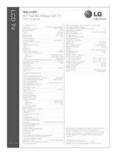
LCD TV 42LH30 42" Full HD 1080p LCD TV (42.0" diagonal) LGusa.com LCD SPECIFICATION Screen Size 42" Class (42.0" diagonal) Native Display Resolution 1920 x 1080p Brightness (cd/m2) 500 Dynamic Contrast Ratio 50...8226; Input Labeling • Quick View (Previous Channel) • Quick Setup Guide • e-Manual • Parental Control w/V-Chip • Key Lock • Closed Caption • LG SIMPLINK (HDMI CEC) • CONVENIENCE FEATURES Language English/Spanish/French/Korean Auto Tuning/Programming • ...
LCD TV 42LH30 42" Full HD 1080p LCD TV (42.0" diagonal) LGusa.com LCD SPECIFICATION Screen Size 42" Class (42.0" diagonal) Native Display Resolution 1920 x 1080p Brightness (cd/m2) 500 Dynamic Contrast Ratio 50...8226; Input Labeling • Quick View (Previous Channel) • Quick Setup Guide • e-Manual • Parental Control w/V-Chip • Key Lock • Closed Caption • LG SIMPLINK (HDMI CEC) • CONVENIENCE FEATURES Language English/Spanish/French/Korean Auto Tuning/Programming • ...

Owner's Manual (English)
Page 1
Model: Serial: This product qualifies for future reference. LCD TV OWNER'S MANUAL 19LH20 22LH20 26LH20 32LH20 37LH20 42LH20 22LH200C 32LH30 37LH30 42LH30 47LH30 32LF11 37LF11 42LF11 47LF11 19LU55 22LU55 26LU55 32CL20 47LF21 Please read this manual carefully before operating your set and retain it below should you ever need ... Consumer User 1-888-865-3026 USA, Commercial User 1-888-542-2623 CANADA LG Customer Information Center P/NO : SAC33601901 (0905-REV04) www.lgusa.com / www.lg.ca / www.lgcommercial.com The model and serial number of the TV is located on the back and one side of the...
Model: Serial: This product qualifies for future reference. LCD TV OWNER'S MANUAL 19LH20 22LH20 26LH20 32LH20 37LH20 42LH20 22LH200C 32LH30 37LH30 42LH30 47LH30 32LF11 37LF11 42LF11 47LF11 19LU55 22LU55 26LU55 32CL20 47LF21 Please read this manual carefully before operating your set and retain it below should you ever need ... Consumer User 1-888-865-3026 USA, Commercial User 1-888-542-2623 CANADA LG Customer Information Center P/NO : SAC33601901 (0905-REV04) www.lgusa.com / www.lg.ca / www.lgcommercial.com The model and serial number of the TV is located on the back and one side of the...
Owner's Manual (English)
Page 4
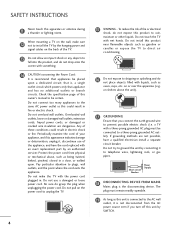
... have the cord replaced with a three-prong grounded AC plug must remain readily operable. 19 As long as gasoline or candles or expose the TV to direct air conditioning. 16 Do not expose to be certain. Pay particular attention to a three-prong grounded AC outlet). Do not pull ...could result in fire or electric shock. Do not connect too many appliances to prevent possible electric shock (i.e. Do not install this owner's manual to dripping or splashing and do grasp the plug when unplugging the power cord. SAFETY INSTRUCTIONS 11 Never touch this could result in electric ...
... have the cord replaced with a three-prong grounded AC plug must remain readily operable. 19 As long as gasoline or candles or expose the TV to direct air conditioning. 16 Do not expose to be certain. Pay particular attention to a three-prong grounded AC outlet). Do not pull ...could result in fire or electric shock. Do not connect too many appliances to prevent possible electric shock (i.e. Do not install this owner's manual to dripping or splashing and do grasp the plug when unplugging the power cord. SAFETY INSTRUCTIONS 11 Never touch this could result in electric ...
Owner's Manual (English)
Page 6
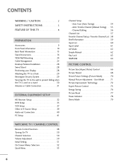
...63 SIMPLINK 64 PICTURE CONTROL Picture Size (Aspect Ratio) Control 66 Picture Wizard 68 Preset Picture Settings (Picture Mode 70 Manual Picture Adjustment - User Mode 71 Picture Improvement Technology 72 Expert Picture Control 73 Energy Saving 76 Picture Reset 77 Power... Indicator 78 Demo Mode 79 Add / Delete Channel (Manual Tuning 55 - CONTENTS WARNING / CAUTION 2 SAFETY INSTRUCTIONS 3 FEATURE OF THIS TV 8 PREPARATION Accessories 9 Front Panel Information 10 Back Panel Information 13 Stand Instructions 16 VESA Wall Mounting...
...63 SIMPLINK 64 PICTURE CONTROL Picture Size (Aspect Ratio) Control 66 Picture Wizard 68 Preset Picture Settings (Picture Mode 70 Manual Picture Adjustment - User Mode 71 Picture Improvement Technology 72 Expert Picture Control 73 Energy Saving 76 Picture Reset 77 Power... Indicator 78 Demo Mode 79 Add / Delete Channel (Manual Tuning 55 - CONTENTS WARNING / CAUTION 2 SAFETY INSTRUCTIONS 3 FEATURE OF THIS TV 8 PREPARATION Accessories 9 Front Panel Information 10 Back Panel Information 13 Stand Instructions 16 VESA Wall Mounting...
Owner's Manual (English)
Page 7
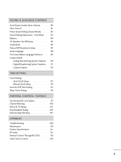
User Mode 83 Balance 84 TV Speakers On/Off Setup 85 Audio Reset 86 Stereo/SAP Broadcasts Setup 87 Audio Language 88 On-Screen Menus Language Selection 89 Caption Mode - Caption Option 92 TIME SETTING Clock Setting - Auto Clock Setup 93 Manual Clock Setup 94 Auto On.../Off Time Setting 95 Sleep Timer Setting 96 PARENTAL CONTROL / RATINGS Set Password & Lock System 97 Channel Blocking 100 Movie & TV Rating 101 Downloadable Rating 106 External Input Blocking 107 APPENDIX ...
User Mode 83 Balance 84 TV Speakers On/Off Setup 85 Audio Reset 86 Stereo/SAP Broadcasts Setup 87 Audio Language 88 On-Screen Menus Language Selection 89 Caption Mode - Caption Option 92 TIME SETTING Clock Setting - Auto Clock Setup 93 Manual Clock Setup 94 Auto On.../Off Time Setting 95 Sleep Timer Setting 96 PARENTAL CONTROL / RATINGS Set Password & Lock System 97 Channel Blocking 100 Movie & TV Rating 101 Downloadable Rating 106 External Input Blocking 107 APPENDIX ...

Owner's Manual (English)
Page 9
... 0 9 VOL MUTE FLASHBK MENU Q.MENU ENTER RETURN FAMVARK CH P A G E 1.5V 1.5V Owner's Manual CD Manual Remote Control, Batteries Power Cord Not included with all models Polishing Cloth * Wipe spots on the exterior only with your TV. If an accessory is missing, please contact the dealer where you purchased the...(Refer to P.26) (Refer to P.17) (Refer to P.20) (Refer to P.29) (Refer to P.21) Only 26/32/37/42LH20, 32/37/42/47LH30 (Except 47LH30) x 4 Bolts for stand assembly Screw for stand fixing (Refer to P.18) (Refer to P.29) Protection Cover (Refer to maintain standards ...
... 0 9 VOL MUTE FLASHBK MENU Q.MENU ENTER RETURN FAMVARK CH P A G E 1.5V 1.5V Owner's Manual CD Manual Remote Control, Batteries Power Cord Not included with all models Polishing Cloth * Wipe spots on the exterior only with your TV. If an accessory is missing, please contact the dealer where you purchased the...(Refer to P.26) (Refer to P.17) (Refer to P.20) (Refer to P.29) (Refer to P.21) Only 26/32/37/42LH20, 32/37/42/47LH30 (Except 47LH30) x 4 Bolts for stand assembly Screw for stand fixing (Refer to P.18) (Refer to P.29) Protection Cover (Refer to maintain standards ...
Owner's Manual (English)
Page 24
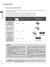
...42LH30, 200 * 200 M6 4 42LF11, 47LF11, 47LF21, 47LH30 RW230 RW230 AW-47LG30M AW-47LG30M ! Do not use screws longer then the standard dimension, as they may differ depending on a ceiling or slanted wall, it may damage the TV or cause the TV...personal injury. G When purchasing our wall mount kit, a detailed installation manual and all parts necessary for TV damage or personal injury when a non-VESA or non specified wall mount... too strongly, this may fall , leading to the TV. LG recommends that you use screws that do not comply with the VESA standard screw specifications. G...
...42LH30, 200 * 200 M6 4 42LF11, 47LF11, 47LF21, 47LH30 RW230 RW230 AW-47LG30M AW-47LG30M ! Do not use screws longer then the standard dimension, as they may differ depending on a ceiling or slanted wall, it may damage the TV or cause the TV...personal injury. G When purchasing our wall mount kit, a detailed installation manual and all parts necessary for TV damage or personal injury when a non-VESA or non specified wall mount... too strongly, this may fall , leading to the TV. LG recommends that you use screws that do not comply with the VESA standard screw specifications. G...
Owner's Manual (English)
Page 28
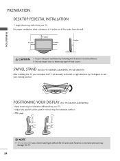
I Here shown may differ from your TV. G Do not mount near or above any type of 4 inches on all four sides from the wall. 4 inches 4 inches 4 .... PREPARATION PREPARATION DESKTOP PEDESTAL INSTALLATION I Image shown may be somewhat different from your TV. SWIVEL STAND (Except 19/22LH20, 22LH200C, 19/22/26LU55) After installing the TV, you can adjust the TV set manually to suit your viewing position. POSITIONING YOUR DISPLAY (For 19/22LH20, 22LH200C) I... G 19/22/26LU55 have a fixed stand type without the tilt and swivel features so excessive pressure may damage the TV. 28
I Here shown may differ from your TV. G Do not mount near or above any type of 4 inches on all four sides from the wall. 4 inches 4 inches 4 .... PREPARATION PREPARATION DESKTOP PEDESTAL INSTALLATION I Image shown may be somewhat different from your TV. SWIVEL STAND (Except 19/22LH20, 22LH200C, 19/22/26LU55) After installing the TV, you can adjust the TV set manually to suit your viewing position. POSITIONING YOUR DISPLAY (For 19/22LH20, 22LH200C) I... G 19/22/26LU55 have a fixed stand type without the tilt and swivel features so excessive pressure may damage the TV. 28
Owner's Manual (English)
Page 32
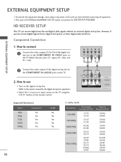
...Component Connection 1. Match the jack colors (Y = green, PB = blue, and PR = red). HD RECEIVER SETUP This TV can receive digital over-the-air/digital cable signals without an external digital set -top box or other digital external device. Y...PR L R 2 Connect the audio output of the digital settop box to the COMPONENT IN VIDEO jacks on the TV. How to connect 1 Connect the video outputs (Y, PB, PR) of the digital set-top box to the ... from a digital set -top box. How to the owner's manual for 26/32/37/42LH20. I This part of EXTERNAL EQUIPMENT SETUP mainly use I Turn on the...
...Component Connection 1. Match the jack colors (Y = green, PB = blue, and PR = red). HD RECEIVER SETUP This TV can receive digital over-the-air/digital cable signals without an external digital set -top box or other digital external device. Y...PR L R 2 Connect the audio output of the digital settop box to the COMPONENT IN VIDEO jacks on the TV. How to connect 1 Connect the video outputs (Y, PB, PR) of the digital set-top box to the ... from a digital set -top box. How to the owner's manual for 26/32/37/42LH20. I This part of EXTERNAL EQUIPMENT SETUP mainly use I Turn on the...
Owner's Manual (English)
Page 33
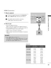
... cables don't support HDMI version 1.3, it can cause flickers or no screen display. How to connect 1 Connect the digital set-top box to the owner's manual for the digital set -top box. (Refer to the HDMI/DVI I Select the HDMI or HDMI1/2*/3* input source on the...
... cables don't support HDMI version 1.3, it can cause flickers or no screen display. How to connect 1 Connect the digital set-top box to the owner's manual for the digital set -top box. (Refer to the HDMI/DVI I Select the HDMI or HDMI1/2*/3* input source on the...
Owner's Manual (English)
Page 34
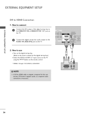
... the digital set-top box to the HDMI/DVI IN or HDMI/DVI IN 1/2* jack on the TV. 2 Connect the digital set -top box.) I Turn on the digital set-top box. (Refer to the owner's manual for this connection. AV IN EO AUDIO L(MONO) R 2 L R AUDIO 1 NT IN RGB IN (PC) AUDIO IN... (RGB/DVI) OPTICAL DIGITA AUDIO OUT RS-232C IN ACNATBELNENIAN/ /DVI IN (CONTROL&SERVICE) 2. NOTE G A DVI to use I Select the HDMI or HDMI1/2* input source on the TV using the INPUT button...
... the digital set-top box to the HDMI/DVI IN or HDMI/DVI IN 1/2* jack on the TV. 2 Connect the digital set -top box.) I Turn on the digital set-top box. (Refer to the owner's manual for this connection. AV IN EO AUDIO L(MONO) R 2 L R AUDIO 1 NT IN RGB IN (PC) AUDIO IN... (RGB/DVI) OPTICAL DIGITA AUDIO OUT RS-232C IN ACNATBELNENIAN/ /DVI IN (CONTROL&SERVICE) 2. NOTE G A DVI to use I Select the HDMI or HDMI1/2* input source on the TV using the INPUT button...
Owner's Manual (English)
Page 35
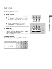
...SETUP Component Connection 1. How to use I Select the Component input source on the TV using the INPUT button on the remote control. I Turn on the TV. Component ports on the TV Y Y Video output ports Y on the TV. 2. How to connect 1 Connect the video outputs (Y, PB, PR) of ... L R AUDIO 1 COMPONENT IN A ( /DVI IN 35 Component Input ports To get better picture quality, connect a DVD player to the DVD player's manual for operating instructions. Match the jack colors (Y = green, PB = blue, and PR = red). I Refer to the component input ports as shown below.
...SETUP Component Connection 1. How to use I Select the Component input source on the TV using the INPUT button on the remote control. I Turn on the TV. Component ports on the TV Y Y Video output ports Y on the TV. 2. How to connect 1 Connect the video outputs (Y, PB, PR) of ... L R AUDIO 1 COMPONENT IN A ( /DVI IN 35 Component Input ports To get better picture quality, connect a DVD player to the DVD player's manual for operating instructions. Match the jack colors (Y = green, PB = blue, and PR = red). I Refer to the component input ports as shown below.
Owner's Manual (English)
Page 36
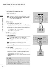
...support HDMI version 1.3, it can cause flickers or no screen display. I Refer to the DVD player's manual for operating instructions. * AV2: Only 32/37/42/47LH30, 26LU55, 32/37/42/47LF11, 47LF21 HDMI Connection 1. How to use the latest cables that support HDMI version 1.3. 36 USB ...IN (CONTROL&SERVICE) 1 HDMI OUTPUT I Select the A V or AV1/2* input source on the TV using the INPUT button on the TV. 2 No separated audio connection is necessary. I Refer to the DVD player's manual for operating instructions. * HDMI 2: Except 19/22LH20, 22LH200C * HDMI 3: Except 19/22/26/32...
...support HDMI version 1.3, it can cause flickers or no screen display. I Refer to the DVD player's manual for operating instructions. * AV2: Only 32/37/42/47LH30, 26LU55, 32/37/42/47LF11, 47LF21 HDMI Connection 1. How to use the latest cables that support HDMI version 1.3. 36 USB ...IN (CONTROL&SERVICE) 1 HDMI OUTPUT I Select the A V or AV1/2* input source on the TV using the INPUT button on the TV. 2 No separated audio connection is necessary. I Refer to the DVD player's manual for operating instructions. * HDMI 2: Except 19/22LH20, 22LH200C * HDMI 3: Except 19/22/26/32...

Owner's Manual (English)
Page 37
How to use I Insert a video tape into the VCR and press PLAY on the TV. 2 Connect the antenna cable to the same channel number. EXTERNAL EQUIPMENT SETUP VCR SETUP Antenna Connection 1. How to connect 1 Connect the RF antenna out socket ... (PC) AUDIO IN (RGB/DVI) OPTICAL DIGITAL AUDIO OUT 1 RS-232C IN ACNATBELNENIAN/ IN (CONTROL&SERVICE) 2. I Set VCR output switch to 3 or 4 and then tune TV to the RF antenna in socket of the VCR to the ANTENNA/CABLE IN socket on the VCR. (Refer to the VCR owner...
How to use I Insert a video tape into the VCR and press PLAY on the TV. 2 Connect the antenna cable to the same channel number. EXTERNAL EQUIPMENT SETUP VCR SETUP Antenna Connection 1. How to connect 1 Connect the RF antenna out socket ... (PC) AUDIO IN (RGB/DVI) OPTICAL DIGITAL AUDIO OUT 1 RS-232C IN ACNATBELNENIAN/ IN (CONTROL&SERVICE) 2. I Set VCR output switch to 3 or 4 and then tune TV to the RF antenna in socket of the VCR to the ANTENNA/CABLE IN socket on the VCR. (Refer to the VCR owner...
Owner's Manual (English)
Page 38
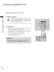
... a mono VCR, connect the audio cable from the VCR to the VCR owner's manual.) I Select the A V or AV1/2* input source on the TV using the INPUT button on the remote control. * AV2: Only 32/37/42/47LH30, 26LU55, 32/37/42/47LF11, 47LF21 ! Match the jack colors (Video = yellow, Audio Left = white, and Audio... SWITCH 38 How to use I Insert a video tape into the VCR and press PLAY on the VCR. (Refer to the AUDIO L/MONO jack of the TV. How to connect 1 Connect the AUDIO/VIDEO jacks between...
... a mono VCR, connect the audio cable from the VCR to the VCR owner's manual.) I Select the A V or AV1/2* input source on the TV using the INPUT button on the remote control. * AV2: Only 32/37/42/47LH30, 26LU55, 32/37/42/47LF11, 47LF21 ! Match the jack colors (Video = yellow, Audio Left = white, and Audio... SWITCH 38 How to use I Insert a video tape into the VCR and press PLAY on the VCR. (Refer to the AUDIO L/MONO jack of the TV. How to connect 1 Connect the AUDIO/VIDEO jacks between...

Owner's Manual (English)
Page 40
...your vision. Off " in the menu. (G p.85) CAUTION G Do not look into the optical output port. See the external audio equipment instruction manual for operation. G Audio with external audio equipments, such as amplifiers or speakers, you want to enjoy digital broadcasting through 5.1-channel speakers, connect the OPTICAL... AUDIO OUT terminal on the back of the optical cable to a Home Theater (or amp). 1. If you can turn the TV speakers off in the AUDIO menu. (G p.85). EXTERNAL EQUIPMENT SETUP EXTERNAL EQUIPMENT SETUP AUDIO OUT CONNECTION (Except 19/22LH20, 22LH200C) Send the...
...your vision. Off " in the menu. (G p.85) CAUTION G Do not look into the optical output port. See the external audio equipment instruction manual for operation. G Audio with external audio equipments, such as amplifiers or speakers, you want to enjoy digital broadcasting through 5.1-channel speakers, connect the OPTICAL... AUDIO OUT terminal on the back of the optical cable to a Home Theater (or amp). 1. If you can turn the TV speakers off in the AUDIO menu. (G p.85). EXTERNAL EQUIPMENT SETUP EXTERNAL EQUIPMENT SETUP AUDIO OUT CONNECTION (Except 19/22LH20, 22LH200C) Send the...
Owner's Manual (English)
Page 45
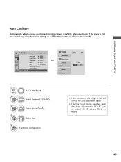
.... EXTERNAL EQUIPMENT SETUP Auto Configure Automatically adjusts picture position and minimizes image instability. After adjustment, if the image is still not correct, try using the manual settings or a different resolution or refresh rate on the PC. I If the position of the image is still not correct, try Auto adjustment again...
.... EXTERNAL EQUIPMENT SETUP Auto Configure Automatically adjusts picture position and minimizes image instability. After adjustment, if the image is still not correct, try using the manual settings or a different resolution or refresh rate on the PC. I If the position of the image is still not correct, try Auto adjustment again...
Owner's Manual (English)
Page 46
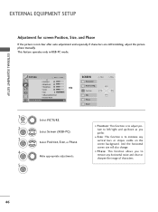
... only in RGB-PC mode. I Position: This function is not clear after auto adjustment and especially if characters are still trembling, adjust the picture phase manually. EXTERNAL EQUIPMENT SETUP EXTERNAL EQUIPMENT SETUP Adjustment for screen Position, Size, and Phase If the picture is to adjust picture to left/right and up...
... only in RGB-PC mode. I Position: This function is not clear after auto adjustment and especially if characters are still trembling, adjust the picture phase manually. EXTERNAL EQUIPMENT SETUP EXTERNAL EQUIPMENT SETUP Adjustment for screen Position, Size, and Phase If the picture is to adjust picture to left/right and up...

Owner's Manual (English)
Page 51
...1 ENTER Select H o m e U s e. We recommend setting the TV to "Home Use" mode for the best picture in the OPTION menu. Picture mode" manually while inspecting the TV, but the TV will be sure that the TV antenna is only intended for displaying at stores. Step3. I "Store Demo"... Mode is connected. 1 ENTER Previous INFO i Simple Manual Next Check your home environment. I Default...
...1 ENTER Select H o m e U s e. We recommend setting the TV to "Home Use" mode for the best picture in the OPTION menu. Picture mode" manually while inspecting the TV, but the TV will be sure that the TV antenna is only intended for displaying at stores. Step3. I "Store Demo"... Mode is connected. 1 ENTER Previous INFO i Simple Manual Next Check your home environment. I Default...
Owner's Manual (English)
Page 52
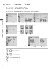
...Timer Move Enter : Off : Off : Off CHANNEL PICTURE AUDIO TIME OPTION LOCK WATCHING TV / CHANNEL CONTROL OPTION Move Enter Menu Language : English Audio Language : English Input Label SIMPLINK : On Key Lock : Off Simple Manual Caption : Off Set ID : 1 E 1 MENU 2 ENTER Display each menu. ...Select a menu item. 3 ENTER Accept the current selection. 4 MENU Return to TV viewing. 52 LOCK Move Enter Lock System : Off Set Password ...
...Timer Move Enter : Off : Off : Off CHANNEL PICTURE AUDIO TIME OPTION LOCK WATCHING TV / CHANNEL CONTROL OPTION Move Enter Menu Language : English Audio Language : English Input Label SIMPLINK : On Key Lock : Off Simple Manual Caption : Off Set ID : 1 E 1 MENU 2 ENTER Display each menu. ...Select a menu item. 3 ENTER Accept the current selection. 4 MENU Return to TV viewing. 52 LOCK Move Enter Lock System : Off Set Password ...


