
Owner's Manual (English)
Page 1
... power-saving guidelines issued by the U.S. ENERGY STAR is a set of the set . LCD TV PLASMA TV OWNER'S MANUAL LCD TV MODELS 32LC7D 32LC7DC 37LC7D 42LC7D PLASMA TV MODELS 42PC5D 42PC5DC 50PC5D 50PC5DC Please read this information to your set . www.lgusa.com / www.lg.ca / www.lgcommercial.com See the label attached on the back cover and...
... power-saving guidelines issued by the U.S. ENERGY STAR is a set of the set . LCD TV PLASMA TV OWNER'S MANUAL LCD TV MODELS 32LC7D 32LC7DC 37LC7D 42LC7D PLASMA TV MODELS 42PC5D 42PC5DC 50PC5D 50PC5DC Please read this information to your set . www.lgusa.com / www.lg.ca / www.lgcommercial.com See the label attached on the back cover and...
Owner's Manual (English)
Page 3
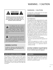
...particular installation. The lightning flash with the instructions, may be determined by turning the equipment off and on a circuit different from LG Electronics. If this equipment does cause harmful interference to radio or television reception, which the receiver is encouraged to try to ...the point of important operating and maintenance (servicing) instructions in a residential installation. Consult the dealer or an experienced radio/TV technician for compliance could void the user's authority to rain or moisture. CAUTION Do not attempt to modify this product to operate...
...particular installation. The lightning flash with the instructions, may be determined by turning the equipment off and on a circuit different from LG Electronics. If this equipment does cause harmful interference to radio or television reception, which the receiver is encouraged to try to ...the point of important operating and maintenance (servicing) instructions in a residential installation. Consult the dealer or an experienced radio/TV technician for compliance could void the user's authority to rain or moisture. CAUTION Do not attempt to modify this product to operate...
Owner's Manual (English)
Page 6
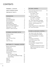
... CONTROL Remote Control Functions 32 Turning On TV 34 Channel Selection 34 Volume Adjustment 34 On-Screen Menus Selection 35 Channel Setup - Auto Scan (Auto Tuning 36 - Channel Editing 38 Input List 39 SimpLink 40 Input Label 42 Key Lock 43 4 PICTURE CONTROL Picture Size (...Aspect Ratio) Control 44 Preset Picture Settings - Picture Improvement Technology 49 Advanced - Caption Option 66 Picture Mode - Preset 45 Color Tone - Color Tone - User Mode . . 57 Balance 58 TV Speakers On/Off Setup ...
... CONTROL Remote Control Functions 32 Turning On TV 34 Channel Selection 34 Volume Adjustment 34 On-Screen Menus Selection 35 Channel Setup - Auto Scan (Auto Tuning 36 - Channel Editing 38 Input List 39 SimpLink 40 Input Label 42 Key Lock 43 4 PICTURE CONTROL Picture Size (...Aspect Ratio) Control 44 Preset Picture Settings - Picture Improvement Technology 49 Advanced - Caption Option 66 Picture Mode - Preset 45 Color Tone - Color Tone - User Mode . . 57 Balance 58 TV Speakers On/Off Setup ...
Owner's Manual (English)
Page 7
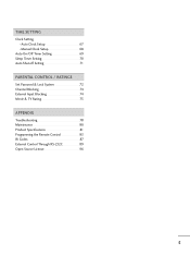
TIME SETTING Clock Setting - Auto Clock Setup 67 Manual Clock Setup 68 Auto On/Off Timer Setting 69 Sleep Timer Setting 70 Auto Shut-off Setting 71 PARENTAL CONTROL / RATINGS Set Password & Lock System 72 Channel Blocking 74 External Input Blocking 74 Movie & TV Rating 75 APPENDIX Troubleshooting 78 Maintenance 80 Product Specifications 81 Programming the Remote Control 83 IR Codes 87 External Control Through RS-232C 89 Open Source License 96 5
TIME SETTING Clock Setting - Auto Clock Setup 67 Manual Clock Setup 68 Auto On/Off Timer Setting 69 Sleep Timer Setting 70 Auto Shut-off Setting 71 PARENTAL CONTROL / RATINGS Set Password & Lock System 72 Channel Blocking 74 External Input Blocking 74 Movie & TV Rating 75 APPENDIX Troubleshooting 78 Maintenance 80 Product Specifications 81 Programming the Remote Control 83 IR Codes 87 External Control Through RS-232C 89 Open Source License 96 5
Owner's Manual (English)
Page 8
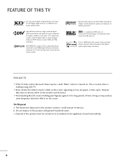
FEATURE OF THIS TV LG's own special digital image generator, consisting of digital television, HDTV...devices with TV. "Dolby "and the double-D symbol are trademarks of SRS Labs, Inc. FOR LCD TV I If the TV feels cold to the HDMI (high-definition multimedia interface), LG TV with this product contains a small amount of LG's audio/... not dispose of your finger(s) against it is nothing wrong with one remote control. I Avoid touching the LCD screen or holding your local authority. 6 c. Manufactured under license from Dolby Laboratories. Disposal of this product must...
FEATURE OF THIS TV LG's own special digital image generator, consisting of digital television, HDTV...devices with TV. "Dolby "and the double-D symbol are trademarks of SRS Labs, Inc. FOR LCD TV I If the TV feels cold to the HDMI (high-definition multimedia interface), LG TV with this product contains a small amount of LG's audio/... not dispose of your finger(s) against it is nothing wrong with one remote control. I Avoid touching the LCD screen or holding your local authority. 6 c. Manufactured under license from Dolby Laboratories. Disposal of this product must...
Owner's Manual (English)
Page 9
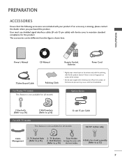
... Cloth * Slightly wipe stained spot on the exterior only with your product. For Plasma TV models This feature is not available for all models 32/37 inches only Cable Management 2- TV Bracket Bolts 2- If an accessory is not available for stand assembly (Refer to p.16...that the following accessories are included with the polishing cloth for the product. ENU ENTER RATIO SIMPLINK CH BRIGHT + TV INPUT TV AUDIO POWER CAMBOLEDDVED INPUT VCR STB BRIGHT - TV Brackets, Twist Holder (Refer to p.12) 7 Wall Brackets Arrange the wires with ferrite cores to p.16) ...
... Cloth * Slightly wipe stained spot on the exterior only with your product. For Plasma TV models This feature is not available for all models 32/37 inches only Cable Management 2- TV Bracket Bolts 2- If an accessory is not available for stand assembly (Refer to p.16...that the following accessories are included with the polishing cloth for the product. ENU ENTER RATIO SIMPLINK CH BRIGHT + TV INPUT TV AUDIO POWER CAMBOLEDDVED INPUT VCR STB BRIGHT - TV Brackets, Twist Holder (Refer to p.12) 7 Wall Brackets Arrange the wires with ferrite cores to p.16) ...
Owner's Manual (English)
Page 10
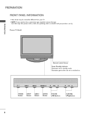
And then wipe the product with a cloth (If a polishing cloth is switched on. INPUT MENU ENTER VOL CH INPUT MENU ENTER VOL CH POWER Button INPUT Button MENU Button ENTER Button VOLUME (F,G)Buttons CHANNEL (E,D)Buttons 8 Plasma TV Model PREPARATION Remote Control Sensor Power/Standby Indicator Illuminates red in standby mode. Illuminates green when the set is included with your TV. PREPARATION FRONT PANEL INFORMATION I NOTE: If your product has a protection tape attached, remove the tape. I Here shown may be somewhat different from your product, use it).
And then wipe the product with a cloth (If a polishing cloth is switched on. INPUT MENU ENTER VOL CH INPUT MENU ENTER VOL CH POWER Button INPUT Button MENU Button ENTER Button VOLUME (F,G)Buttons CHANNEL (E,D)Buttons 8 Plasma TV Model PREPARATION Remote Control Sensor Power/Standby Indicator Illuminates red in standby mode. Illuminates green when the set is included with your TV. PREPARATION FRONT PANEL INFORMATION I NOTE: If your product has a protection tape attached, remove the tape. I Here shown may be somewhat different from your product, use it).
Owner's Manual (English)
Page 11
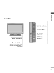
Illuminates green when the set is switched on. CH VOL ENTER MENU INPUT CH VOL ENTER MENU INPUT CHANNEL (D,E)Buttons VOLUME (F,G)Buttons ENTER Button MENU Button INPUT Button POWER Button 9 PREPARATION LCD TV Model Remote Control Sensor Power/Standby Indicator Illuminates red in standby mode.
Illuminates green when the set is switched on. CH VOL ENTER MENU INPUT CH VOL ENTER MENU INPUT CHANNEL (D,E)Buttons VOLUME (F,G)Buttons ENTER Button MENU Button INPUT Button POWER Button 9 PREPARATION LCD TV Model Remote Control Sensor Power/Standby Indicator Illuminates red in standby mode.
Owner's Manual (English)
Page 13
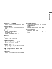
... the audio from a PC or DTV. 4 SERVICE 5 Remote Control Port Connect a wired remote control. 6 ANTENNA/CABLE IN Connect over-the air signals to operate the TV on DC power. 11
... the audio from a PC or DTV. 4 SERVICE 5 Remote Control Port Connect a wired remote control. 6 ANTENNA/CABLE IN Connect over-the air signals to operate the TV on DC power. 11
Owner's Manual (English)
Page 14
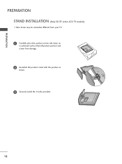
PREPARATION PREPARATION STAND INSTALLATION (Only 32/37 inches LCD TV models) I Here shown may be somewhat different from your TV. 1 Carefully place the product screen side down on a cushioned surface that will protect product and screen from damage. 2 Assemble the product stand with the product as shown. 3 Securely install the 4 bolts provided. 12
PREPARATION PREPARATION STAND INSTALLATION (Only 32/37 inches LCD TV models) I Here shown may be somewhat different from your TV. 1 Carefully place the product screen side down on a cushioned surface that will protect product and screen from damage. 2 Assemble the product stand with the product as shown. 3 Securely install the 4 bolts provided. 12
Owner's Manual (English)
Page 15
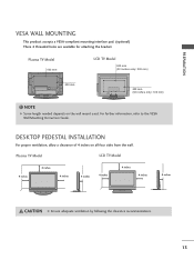
Plasma TV Model LCD TV Model 4 inches 4 inches 4 inches 4 inches 4 inches 4 inches 4 inches 4 inches CAUTION G Ensure adequate ventilation by following the clearance recommendations. 13 PREPARATION VESA WALL MOUNTING This product ... pad. (optional) There 4 threaded holes are available for attaching the bracket. NOTE G Screw length needed depends on all four sides from the wall. Plasma TV Model 600 mm LCD TV Model 600 mm (32 inches only: 200 mm) R R 400 mm 400 mm (32 inches only: 100 mm) ! For further information, refer to the...
Plasma TV Model LCD TV Model 4 inches 4 inches 4 inches 4 inches 4 inches 4 inches 4 inches 4 inches CAUTION G Ensure adequate ventilation by following the clearance recommendations. 13 PREPARATION VESA WALL MOUNTING This product ... pad. (optional) There 4 threaded holes are available for attaching the bracket. NOTE G Screw length needed depends on all four sides from the wall. Plasma TV Model 600 mm LCD TV Model 600 mm (32 inches only: 200 mm) R R 400 mm 400 mm (32 inches only: 100 mm) ! For further information, refer to the...
Owner's Manual (English)
Page 16
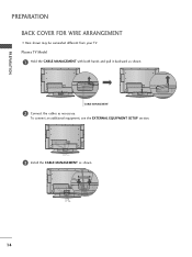
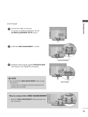
CABLE MANAGEMENT 2 Connect the cables as shown. 14 PREPARATION PREPARATION BACK COVER FOR WIRE ARRANGEMENT I Here shown may be somewhat different from your TV. To connect an additional equipment, see the EXTERNAL EQUIPMENT SETUP section. 3 Install the CABLE MANAGEMENT as necessary. Plasma TV Model 1 Hold the CABLE MANAGEMENT with both hands and pull it backward as shown.
CABLE MANAGEMENT 2 Connect the cables as shown. 14 PREPARATION PREPARATION BACK COVER FOR WIRE ARRANGEMENT I Here shown may be somewhat different from your TV. To connect an additional equipment, see the EXTERNAL EQUIPMENT SETUP section. 3 Install the CABLE MANAGEMENT as necessary. Plasma TV Model 1 Hold the CABLE MANAGEMENT with both hands and pull it backward as shown.
Owner's Manual (English)
Page 17
TWIST HOLDER 15 NOTE G Do not hold the CABLE MANAGEMENT when moving the product. - PREPARATION LCD TV Model 1 Connect the cables as shown. 3 Bundle the cables using the supplied TWISTER HOLDER. (This feature is dropped, you may be injured or the product may be broken. To connect an additional equipment, see the EXTERNAL EQUIPMENT SETUP section. 2 Install the CABLE MANAGEMENT as necessary. How to remove the CABLE MANAGEMENT G Hold the CABLE MANAGEMENT with both hands and pull it backward. If the product is not available for all models.) CABLE MANAGEMENT !
TWIST HOLDER 15 NOTE G Do not hold the CABLE MANAGEMENT when moving the product. - PREPARATION LCD TV Model 1 Connect the cables as shown. 3 Bundle the cables using the supplied TWISTER HOLDER. (This feature is dropped, you may be injured or the product may be broken. To connect an additional equipment, see the EXTERNAL EQUIPMENT SETUP section. 2 Install the CABLE MANAGEMENT as necessary. How to remove the CABLE MANAGEMENT G Hold the CABLE MANAGEMENT with both hands and pull it backward. If the product is not available for all models.) CABLE MANAGEMENT !
Owner's Manual (English)
Page 18
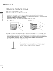
...set up the TV close to a wall so it cannot fall over if pushed backwards. I Here shown may be pulled in a forward direction, potentially causing injury or damaging the product. Match the height of the product, must purchase separately) to tie the product. Plasma TV Model LCD TV Model I ...Insert the eye-bolts (or TV brackets and bolts) to tighten the product to the wall as parts of the bracket that the...
...set up the TV close to a wall so it cannot fall over if pushed backwards. I Here shown may be pulled in a forward direction, potentially causing injury or damaging the product. Match the height of the product, must purchase separately) to tie the product. Plasma TV Model LCD TV Model I ...Insert the eye-bolts (or TV brackets and bolts) to tighten the product to the wall as parts of the bracket that the...
Owner's Manual (English)
Page 19
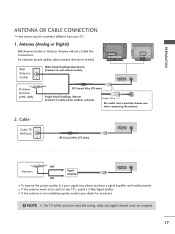
R ANTENNA OR CABLE CONNECTION I Here shown may be split for assistance. ( ) ! Cable Cable TV Wall Jack RF Coaxial Wire (75 ohm) ANTENNA/ CABLE IN ( ) Antenna UHF Signal Amplifier VHF ANTENNA/ CABLE IN I If the antenna needs to bend ...the bronze wire when connecting the antenna. ( ) R 2. I If the antenna is not installed properly, contact your TV. 1. Antenna (Analog or Digital) Wall Antenna Socket or Outdoor Antenna without a Cable Box Connections. NOTE G The TV will let you know when the analog, cable, and digital channel scans are complete. 17 I To improve...
R ANTENNA OR CABLE CONNECTION I Here shown may be split for assistance. ( ) ! Cable Cable TV Wall Jack RF Coaxial Wire (75 ohm) ANTENNA/ CABLE IN ( ) Antenna UHF Signal Amplifier VHF ANTENNA/ CABLE IN I If the antenna needs to bend ...the bronze wire when connecting the antenna. ( ) R 2. I If the antenna is not installed properly, contact your TV. 1. Antenna (Analog or Digital) Wall Antenna Socket or Outdoor Antenna without a Cable Box Connections. NOTE G The TV will let you know when the analog, cable, and digital channel scans are complete. 17 I To improve...
Owner's Manual (English)
Page 20
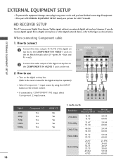
... output of the digital set-top box to 1 the COMPONENT IN AUDIO 1 jacks on the digital set-top box. (Refer to the owner's manual for LCD TV model. VIDEO AUDIO S-V ( /DVI IN 2. How to use I This part of the digital set top box to the COMPONENT IN VIDEO 1 jacks on the remote... INPUT button on MI IN the set -top box or other digital external device, refer to the figure as shown below. HD RECEIVER SETUP This TV can receive Digital Over-the-air/Cable signals without an external digital set . How to connect 1 Connect the video outputs (Y, PB, PR) of EXTERNAL EQUIPMENT...
... output of the digital set-top box to 1 the COMPONENT IN AUDIO 1 jacks on the digital set-top box. (Refer to the owner's manual for LCD TV model. VIDEO AUDIO S-V ( /DVI IN 2. How to use I This part of the digital set top box to the COMPONENT IN VIDEO 1 jacks on the remote... INPUT button on MI IN the set -top box or other digital external device, refer to the figure as shown below. HD RECEIVER SETUP This TV can receive Digital Over-the-air/Cable signals without an external digital set . How to connect 1 Connect the video outputs (Y, PB, PR) of EXTERNAL EQUIPMENT...
Owner's Manual (English)
Page 23
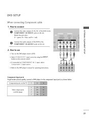
I If connected to COMPONENT IN 2 input, select Component 2 input source. 1 2 I Turn on the DVD player, insert a DVD. Component ports on the TV Y PB PR Video output ports on the set . COMPONENT IN 2 RS (CONTR 2. RGB IN RGB(PC) AUDIO REM (RGB/DVI) SERVICE CONT 2 Connect the audio ...
I If connected to COMPONENT IN 2 input, select Component 2 input source. 1 2 I Turn on the DVD player, insert a DVD. Component ports on the TV Y PB PR Video output ports on the set . COMPONENT IN 2 RS (CONTR 2. RGB IN RGB(PC) AUDIO REM (RGB/DVI) SERVICE CONT 2 Connect the audio ...
Owner's Manual (English)
Page 25
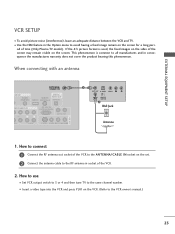
... use I Use the ISM feature in socket of the screen may remain visible on the screen. I Set VCR output switch to 3 or 4 and then tune TV to the same channel number. How to connect 1 Connect the RF antenna out socket of the VCR to the ANTENNA/CABLE IN socket on the... a fixed image remain on the screen for a long peri- I To avoid picture noise (interference), leave an adequate distance between the VCR and TV. od of time (Only Plasma TV model). EXTERNAL EQUIPMENT SETUP VCR SETUP I Insert a video tape into the VCR and press PLAY on the VCR. (Refer to the VCR owner...
... use I Use the ISM feature in socket of the screen may remain visible on the screen. I Set VCR output switch to 3 or 4 and then tune TV to the same channel number. How to connect 1 Connect the RF antenna out socket of the VCR to the ANTENNA/CABLE IN socket on the... a fixed image remain on the screen for a long peri- I To avoid picture noise (interference), leave an adequate distance between the VCR and TV. od of time (Only Plasma TV model). EXTERNAL EQUIPMENT SETUP VCR SETUP I Insert a video tape into the VCR and press PLAY on the VCR. (Refer to the VCR owner...

Owner's Manual (English)
Page 26
... A V 2 input source. How to the S -VIDEO input on the set . NOTE G The picture quality is improved: compared to connect 1 Connect the AUDIO/VIDEO jacks between TV and VCR. ( ) EXTERNAL EQUIPMENT SETUP EXTERNAL EQUIPMENT SETUP When connecting with an S-Video cable 1. NOTE G If you connect both Video and S-Video at the same...
... A V 2 input source. How to the S -VIDEO input on the set . NOTE G The picture quality is improved: compared to connect 1 Connect the AUDIO/VIDEO jacks between TV and VCR. ( ) EXTERNAL EQUIPMENT SETUP EXTERNAL EQUIPMENT SETUP When connecting with an S-Video cable 1. NOTE G If you connect both Video and S-Video at the same...

Owner's Manual (English)
Page 27
I If connected to connect 1 Connect the AUDIO/VIDEO jacks between TV and external equipment. EXTERNAL EQUIPMENT SETUP OTHER A/V SOURCE SETUP 1. How to AV IN1 input, select A V 1 input source. VIDEO L/MONO AUDIO R Camcorder Video Game Set VIDEO L R S-VIDEO 1 AV IN 2 25 How to use I Operate the corresponding external equipment. Match the jack colors. (Video = yellow, Audio Left = white, and Audio Right = red) 2. I Select A V 2 input source by using the INPUT button on the remote control.
I If connected to connect 1 Connect the AUDIO/VIDEO jacks between TV and external equipment. EXTERNAL EQUIPMENT SETUP OTHER A/V SOURCE SETUP 1. How to AV IN1 input, select A V 1 input source. VIDEO L/MONO AUDIO R Camcorder Video Game Set VIDEO L R S-VIDEO 1 AV IN 2 25 How to use I Operate the corresponding external equipment. Match the jack colors. (Video = yellow, Audio Left = white, and Audio Right = red) 2. I Select A V 2 input source by using the INPUT button on the remote control.


