Owners Manual
Page 1
OWNER'S MANUAL LCD TV Please read this manual carefully before operating your set and retain it for future reference. 26LH210C 32LH210C 26LH200C 32LH200C 37LH200C 42LH200C 42LH300C 47LH300C P/NO : SAC34026003 (1004-REV01) www.lg.com
OWNER'S MANUAL LCD TV Please read this manual carefully before operating your set and retain it for future reference. 26LH210C 32LH210C 26LH200C 32LH200C 37LH200C 42LH200C 42LH300C 47LH300C P/NO : SAC34026003 (1004-REV01) www.lg.com

Owners Manual
Page 4
... or mechanical abuse, such as being twisted, kinked, pinched, closed in electric shock or fire. SAFETY INSTRUCTIONS 11 Never touch this owner's manual to be certain. Check the specification page of your appliance, and if its appearance indicates damage or deterioration, unplug it, discontinue use...install this product near flammable objects such as gasoline or candles or expose the TV to direct air conditioning. 16 Do not expose to telephone wires, lightening rods, or gas pipes. When mounting a TV on shelves above the unit). 17 GROUNDING Ensure that appliances be connected to...
... or mechanical abuse, such as being twisted, kinked, pinched, closed in electric shock or fire. SAFETY INSTRUCTIONS 11 Never touch this owner's manual to be certain. Check the specification page of your appliance, and if its appearance indicates damage or deterioration, unplug it, discontinue use...install this product near flammable objects such as gasoline or candles or expose the TV to direct air conditioning. 16 Do not expose to telephone wires, lightening rods, or gas pipes. When mounting a TV on shelves above the unit). 17 GROUNDING Ensure that appliances be connected to...

Owners Manual
Page 9
...0 9 VOL MUTE FLASHBK MENU Q.MENU ENTER RETURN FAMVARK CH P A G E 1.5V 1.5V (For 26LH210C, 32LH210C) MUTE SAP INFO CC POWER 1 4 7 5 8 TIMER 0 INPUT 9 FLASHBK RETURN VOL CH OK CH VOL 2 3 6 BED1 BED2 1.5V 1.5V Owner's Manual CD Manual Installer Remote Control, User Remote Control, Batteries Batteries Power Cord (Except 47LH300C) x 4 Screws for stand...pin Cable When using the VGA (D-sub 15 pin cable) PC connection, the user must use shielded signal interface cables with your TV. If an accessory is missing, please contact the dealer where you purchased the...
...0 9 VOL MUTE FLASHBK MENU Q.MENU ENTER RETURN FAMVARK CH P A G E 1.5V 1.5V (For 26LH210C, 32LH210C) MUTE SAP INFO CC POWER 1 4 7 5 8 TIMER 0 INPUT 9 FLASHBK RETURN VOL CH OK CH VOL 2 3 6 BED1 BED2 1.5V 1.5V Owner's Manual CD Manual Installer Remote Control, User Remote Control, Batteries Batteries Power Cord (Except 47LH300C) x 4 Screws for stand...pin Cable When using the VGA (D-sub 15 pin cable) PC connection, the user must use shielded signal interface cables with your TV. If an accessory is missing, please contact the dealer where you purchased the...
Owners Manual
Page 20
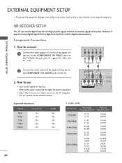
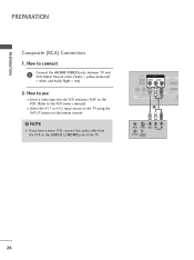
... VIDEO COMPONENT IN L AUDIO R L R SPEAKER OUT /DVI IN REMO CONTRO Supported Resolutions Signal Component 480i Yes 480p Yes 720p Yes 1080i Yes 1080p Yes HDMI No Yes Yes Yes Yes 20 Y, CB/PB, CR/PR Resolution Horizontal Vertical Frequency(KHz) Frequency(Hz) 720x480i 720x480p 1280x720p ...video outputs (Y, PB, PR) of the digital set-top box to the owner's manual for the digital set-top box operation.) I Select the Component input source on the TV using the INPUT button on the TV. 2. However, if you have finished connecting all equipment. Match the jack colors...
... VIDEO COMPONENT IN L AUDIO R L R SPEAKER OUT /DVI IN REMO CONTRO Supported Resolutions Signal Component 480i Yes 480p Yes 720p Yes 1080i Yes 1080p Yes HDMI No Yes Yes Yes Yes 20 Y, CB/PB, CR/PR Resolution Horizontal Vertical Frequency(KHz) Frequency(Hz) 720x480i 720x480p 1280x720p ...video outputs (Y, PB, PR) of the digital set-top box to the owner's manual for the digital set-top box operation.) I Select the Component input source on the TV using the INPUT button on the TV. 2. However, if you have finished connecting all equipment. Match the jack colors...
Owners Manual
Page 21
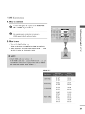
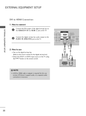
...to use the latest cables that support HDMI version 1.3. If the HDMI cables don't support HDMI version 1.3, it can cause flickers or no screen display. How to connect 1 Connect the digital set-top box to the owner's manual for the digital set -top box. (Refer to the HDMI/DVI I Select the HDMI1 or ...HDMI2 input source on the TV using the INPUT button on the TV. 2 No separate audio connection is necessary. HDMI supports both audio and video. 2. In this case...
...to use the latest cables that support HDMI version 1.3. If the HDMI cables don't support HDMI version 1.3, it can cause flickers or no screen display. How to connect 1 Connect the digital set-top box to the owner's manual for the digital set -top box. (Refer to the HDMI/DVI I Select the HDMI1 or ...HDMI2 input source on the TV using the INPUT button on the TV. 2 No separate audio connection is necessary. HDMI supports both audio and video. 2. In this case...
Owners Manual
Page 22
NOTE G A DVI to the owner's manual for this connection. EXTERNAL EQUIPMENT SETUP EXTERNAL EQUIPMENT SETUP DVI to the AUDIO IN (RGB/DVI) jack on the TV. 2. AV IN 1 O AUDIO 2 L(MONO) R 1 L AUDIO R L R SPEAKER OUT RGB IN (PC) AUDIO IN /DVI IN (RGB/DVI) OPTICAL DIGIT AUDIO OUT REMOTE ...CONTROL&SERVICE) 1 2 ! DVI OUTPUT L R AUDIO 22 How to connect 1 Connect the DVI output of the digital set-top box to the HDMI/DVI IN 1or HDMI 2 jack on the remote control. DVI doesn't support audio, so a separate audio connection is required for the digital set-top box.) I Select the...
NOTE G A DVI to the owner's manual for this connection. EXTERNAL EQUIPMENT SETUP EXTERNAL EQUIPMENT SETUP DVI to the AUDIO IN (RGB/DVI) jack on the TV. 2. AV IN 1 O AUDIO 2 L(MONO) R 1 L AUDIO R L R SPEAKER OUT RGB IN (PC) AUDIO IN /DVI IN (RGB/DVI) OPTICAL DIGIT AUDIO OUT REMOTE ...CONTROL&SERVICE) 1 2 ! DVI OUTPUT L R AUDIO 22 How to connect 1 Connect the DVI output of the digital set-top box to the HDMI/DVI IN 1or HDMI 2 jack on the remote control. DVI doesn't support audio, so a separate audio connection is required for the digital set-top box.) I Select the...

Owners Manual
Page 25
... Antenna Connection 1. How to use I Insert a video tape into the VCR and press PLAY on the TV. 2 Connect the antenna cable to the same channel number. I Set VCR output switch to 3 or 4 and then tune TV to the RF antenna in socket of the VCR. RGB IN (PC) DIO IN GB/DVI...) 2. How to connect 1 Connect the RF antenna out socket of the VCR to the ANTENNA/CABLE IN socket on the VCR. (Refer to the VCR owner's manual.) 1 ANT OUT S-VIDEO VIDEO L R AUDIO ANT IN OUTPUT SWITCH Wall Jack 2 Antenna 25
... Antenna Connection 1. How to use I Insert a video tape into the VCR and press PLAY on the TV. 2 Connect the antenna cable to the same channel number. I Set VCR output switch to 3 or 4 and then tune TV to the RF antenna in socket of the VCR. RGB IN (PC) DIO IN GB/DVI...) 2. How to connect 1 Connect the RF antenna out socket of the VCR to the ANTENNA/CABLE IN socket on the VCR. (Refer to the VCR owner's manual.) 1 ANT OUT S-VIDEO VIDEO L R AUDIO ANT IN OUTPUT SWITCH Wall Jack 2 Antenna 25
Owners Manual
Page 26
... you have a mono VCR, connect the audio cable from the VCR to the VCR owner's manual.) I Select the A V 1 or A V 2 input source on the TV using the INPUT button on the VCR. (Refer to the AUDIO L/MONO jack of the TV. Match the jack colors (Video = yellow, Audio Left = white, and Audio Right = red). 2. How...
... you have a mono VCR, connect the audio cable from the VCR to the VCR owner's manual.) I Select the A V 1 or A V 2 input source on the TV using the INPUT button on the VCR. (Refer to the AUDIO L/MONO jack of the TV. Match the jack colors (Video = yellow, Audio Left = white, and Audio Right = red). 2. How...


