
Owners Manual
Page 3
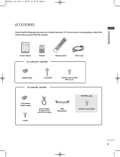
... you purchased the product. INDEX 9 FAV Owner's Manual Batteries Remote Control Power Cord For 42PC1RV*, 42PC3RV* 2-Wall brackets 2-eye-bolts For 26LC2R*, 32LC2R* 2-bolts for stand assembly 2-bolts 1 PIP PIP PR+ TV DVD SIZE VCR PIP POSTION INPUT MENU I/II OK SLEEP VOL Q.VIEW 1 MUTE PR 4 ...2 7 5 3 * 8 6 TIME 0 REVEAL ? Cable Management 32LC2R* only 4-bolts for stand assembly Refer to p.12 2-TV brackets 2-Wall brackets Twister Holder Arrange the wires with your TV. ACCESSORIES 0323G_1-en_rev01 2/28/06 4:12 PM ...
... you purchased the product. INDEX 9 FAV Owner's Manual Batteries Remote Control Power Cord For 42PC1RV*, 42PC3RV* 2-Wall brackets 2-eye-bolts For 26LC2R*, 32LC2R* 2-bolts for stand assembly 2-bolts 1 PIP PIP PR+ TV DVD SIZE VCR PIP POSTION INPUT MENU I/II OK SLEEP VOL Q.VIEW 1 MUTE PR 4 ...2 7 5 3 * 8 6 TIME 0 REVEAL ? Cable Management 32LC2R* only 4-bolts for stand assembly Refer to p.12 2-TV brackets 2-Wall brackets Twister Holder Arrange the wires with your TV. ACCESSORIES 0323G_1-en_rev01 2/28/06 4:12 PM ...

Owners Manual
Page 4
... (SSM - 0323G_1-en_rev01 2/28/06 4:12 PM Page 2 CONTENTS CONTENTS ACCESSORIES 1 INTRODUCTION Controls / Connection Options 4-9 Remote Control Key Functions 10-11 Installing Batteries 11 INSTALLATION Stand Installation 12-13 Basic Connection / How to Remove the Cable Management 14-15 How to join the product assembly to the wall to protect the...
... (SSM - 0323G_1-en_rev01 2/28/06 4:12 PM Page 2 CONTENTS CONTENTS ACCESSORIES 1 INTRODUCTION Controls / Connection Options 4-9 Remote Control Key Functions 10-11 Installing Batteries 11 INSTALLATION Stand Installation 12-13 Basic Connection / How to Remove the Cable Management 14-15 How to join the product assembly to the wall to protect the...

Owners Manual
Page 14
... damage to the set with the screen facing down on a cushion or soft cloth as shown above in Figures 1. I Pull the stand out as shown in Figures 2 ~ 3. When closing the stand for all models. 1 2 A INSTALLATION 3 4 B C I Place the set ,Do not disengage the lock (C). 0323G_1-en_rev01 2/28/06...holes (B)on the bottom of the stand.And then pull two Hooks (D)of the stand bottom and fold the stand into the back of the set . Before unfolding the stand,please make sure two locks (A)on the bottom of the stand. After folding,push two Locks (A)of the stand bottom outward. 12 D A ...
... damage to the set with the screen facing down on a cushion or soft cloth as shown above in Figures 1. I Pull the stand out as shown in Figures 2 ~ 3. When closing the stand for all models. 1 2 A INSTALLATION 3 4 B C I Place the set ,Do not disengage the lock (C). 0323G_1-en_rev01 2/28/06...holes (B)on the bottom of the stand.And then pull two Hooks (D)of the stand bottom and fold the stand into the back of the set . Before unfolding the stand,please make sure two locks (A)on the bottom of the stand. After folding,push two Locks (A)of the stand bottom outward. 12 D A ...

Owners Manual
Page 15
INSTALLATION 0323G_1-en_rev01 2/28/06 4:12 PM Page 13 STAND INSTALLATION (Only 32LC2R*) 1 Carefully place the product screen side down on a cushioned surface that will protect product and screen from damage. 2 Place the product stand on the product as shown. 3 Install the 4 bolts securely, in the back of the product in the holes provided. 13
INSTALLATION 0323G_1-en_rev01 2/28/06 4:12 PM Page 13 STAND INSTALLATION (Only 32LC2R*) 1 Carefully place the product screen side down on a cushioned surface that will protect product and screen from damage. 2 Place the product stand on the product as shown. 3 Install the 4 bolts securely, in the back of the product in the holes provided. 13

Owners Manual
Page 16
INSTALLATION Stand type 2 1 Hold the CABLE MANAGEMENT with both hands and push it as shown. 2 Connect the cables as shown picture. Stand type 1 Arrange the cables as necessary. 0323G_1-en_rev01 2/28/06 4:12 PM Page 14 INSTALLATION BASIC CONNECTION (42PC1RV*, 42PC3RV*) I These models have two cable arrangement methods according to the stand type. To connect an additional equipment, see the External equipment Connections section. 3 Reinstall the CABLE MANAGEMENT as shown. 14 CABLE MANAGEMENT
INSTALLATION Stand type 2 1 Hold the CABLE MANAGEMENT with both hands and push it as shown. 2 Connect the cables as shown picture. Stand type 1 Arrange the cables as necessary. 0323G_1-en_rev01 2/28/06 4:12 PM Page 14 INSTALLATION BASIC CONNECTION (42PC1RV*, 42PC3RV*) I These models have two cable arrangement methods according to the stand type. To connect an additional equipment, see the External equipment Connections section. 3 Reinstall the CABLE MANAGEMENT as shown. 14 CABLE MANAGEMENT

Owners Manual
Page 77
...26LC2R* 26LC2R-TJ Dimensions (Width x Height x Depth) with stand without stand 681.0 x 542.0 x 172.0 mm 26.8 x 21.3 x 6.8 inches 681.0 x 490.8 x 119.0 mm 26.8 x 19.3 x 4.6 inches 32LC2R* 32LC2R-TJ 811.0 x 630.0 x 235.0 mm 31.9 x 24.8 x 9.3 inches 811.0 x 566.8 x 123.5 mm 31.9 x 22.3 x 4.9 inches Weight with stand without stand...Temperature Storage Humidity -20 ~ 60°C / -4 ~ 140°F Less than 85% APPENDIX MODELS Dimensions (Width x Height x Depth) including stand excluding stand 42PC1RV* 42PC1RV-TJ 1129.0 x 748.5 x 380.0 mm 44.4 x 29.5 x 15.0 inches 1129.0 x 695.0 x 103.7 mm ...
...26LC2R* 26LC2R-TJ Dimensions (Width x Height x Depth) with stand without stand 681.0 x 542.0 x 172.0 mm 26.8 x 21.3 x 6.8 inches 681.0 x 490.8 x 119.0 mm 26.8 x 19.3 x 4.6 inches 32LC2R* 32LC2R-TJ 811.0 x 630.0 x 235.0 mm 31.9 x 24.8 x 9.3 inches 811.0 x 566.8 x 123.5 mm 31.9 x 22.3 x 4.9 inches Weight with stand without stand...Temperature Storage Humidity -20 ~ 60°C / -4 ~ 140°F Less than 85% APPENDIX MODELS Dimensions (Width x Height x Depth) including stand excluding stand 42PC1RV* 42PC1RV-TJ 1129.0 x 748.5 x 380.0 mm 44.4 x 29.5 x 15.0 inches 1129.0 x 695.0 x 103.7 mm ...

Service Manual
Page 11
11. Product Weight Only SET With BOX 11.2 32LC2R No 1. Mechanical Specification 11.1 26LC2R No Item 1. Product Dimension Before Packing After Packing 2. Product Weight Item Before Packing After Packing Only SET With BOX Width 681 749 Width 811 896 Content Length Height 235 550 275 640 16.8 18.9 Content Length Height 235 630 300 720 22 25.5 Remark Unit mm SET(With Stand) mm Kg Kg Remark Unit mm SET(With Stand) mm Kg Kg - 11 - Product Dimension 2.
11. Product Weight Only SET With BOX 11.2 32LC2R No 1. Mechanical Specification 11.1 26LC2R No Item 1. Product Dimension Before Packing After Packing 2. Product Weight Item Before Packing After Packing Only SET With BOX Width 681 749 Width 811 896 Content Length Height 235 550 275 640 16.8 18.9 Content Length Height 235 630 300 720 22 25.5 Remark Unit mm SET(With Stand) mm Kg Kg Remark Unit mm SET(With Stand) mm Kg Kg - 11 - Product Dimension 2.

Service Manual
Page 14
... S/W off (Disconnect SCL to GND using switch at Jig ) and connect the download jig to GND using switch at the "edit window" (2) Supply the power (Stand-by 5V) and wait for 3 seconds. (9) Under Downloading process (10) If download is failed, for example "No acknowledge from slave". (8) Click OK button at jig...
... S/W off (Disconnect SCL to GND using switch at Jig ) and connect the download jig to GND using switch at the "edit window" (2) Supply the power (Stand-by 5V) and wait for 3 seconds. (9) Under Downloading process (10) If download is failed, for example "No acknowledge from slave". (8) Click OK button at jig...

Service Manual
Page 32
... 405AF-DMS 3809900134A Cover Assembly, 26LC2 NON LG BRAND 3809900134D Cover Assembly, 26LC2 NON LG BRAND 405AF(C/SKD)-DMS 3809900134B Cover Assembly, 26LC2 NON LG BRAND CSKD 040 3043900029A Base Assembly, 26LC2R 3043900029A STAND TOTAL ASSY 3043900026E Base Assembly, 32LC2R NONE STAND BOTTOM C/SKD WITH PRINTING 3043900029B Base Assembly, 26LC2R 3043900029A STAND BODY ASSY C/SKD 050 68719ST934A PCB...
... 405AF-DMS 3809900134A Cover Assembly, 26LC2 NON LG BRAND 3809900134D Cover Assembly, 26LC2 NON LG BRAND 405AF(C/SKD)-DMS 3809900134B Cover Assembly, 26LC2 NON LG BRAND CSKD 040 3043900029A Base Assembly, 26LC2R 3043900029A STAND TOTAL ASSY 3043900026E Base Assembly, 32LC2R NONE STAND BOTTOM C/SKD WITH PRINTING 3043900029B Base Assembly, 26LC2R 3043900029A STAND BODY ASSY C/SKD 050 68719ST934A PCB...

Service Manual
Page 34
... . EXPLODED VIEW PARTS LIST(32LC2R) No. Local for DMS 140 35509K0199A Cover, MOLD HIPS 32LC2 REAR STAND SUPPORTER 150 35509K0197A Cover, MOLD HIPS 32LC2 CABLE MANAGEMENT - 34 - Non EU 33139L3028E Main Total Assembly,... H3-M 110 49509K0195A Plate, CASTING AL FRAME SUPPORT 32LC2 120 68719ST934A PCB Assembly,Sub, SUB T.T LP61A 26LC2R ZJ LOCAL EBR30372601 PCB Assembly,Sub, SUB T.T LP61A 32LC2R . SIDE AV for DMS 080 6709900016C SMPS,...Power Supply Assembly, FREE H3/E2 LCD MODEL LCD LG ELECTRONICS LB LC 090 33139L3028A Main Total Assembly, 32LC2R(AUO) BRAND LC61A - PART NO.
... . EXPLODED VIEW PARTS LIST(32LC2R) No. Local for DMS 140 35509K0199A Cover, MOLD HIPS 32LC2 REAR STAND SUPPORTER 150 35509K0197A Cover, MOLD HIPS 32LC2 CABLE MANAGEMENT - 34 - Non EU 33139L3028E Main Total Assembly,... H3-M 110 49509K0195A Plate, CASTING AL FRAME SUPPORT 32LC2 120 68719ST934A PCB Assembly,Sub, SUB T.T LP61A 26LC2R ZJ LOCAL EBR30372601 PCB Assembly,Sub, SUB T.T LP61A 32LC2R . SIDE AV for DMS 080 6709900016C SMPS,...Power Supply Assembly, FREE H3/E2 LCD MODEL LCD LG ELECTRONICS LB LC 090 33139L3028A Main Total Assembly, 32LC2R(AUO) BRAND LC61A - PART NO.


