
FS-C5020/C5030 Operation Guide (Basic Edition)
Page 8
... Some jurisdictions do not allow these limitations or exclusions, so they may not apply to you. 4. If you acquired the Program in the United States, this license, IBM's liability will be for actual damages only and will not be limited to you based on any way to IBM....Garde Gothic, ITC Bookman, ITC ZapfChancery and ITC Zapf Dingbats are licensed from this printer are registered trademarks of Programs supplied to this license is governed by the laws of the Province of Ontario. Such developer is the following; vi BASIC OPERATION GUIDE General You may bring an action, ...
... Some jurisdictions do not allow these limitations or exclusions, so they may not apply to you. 4. If you acquired the Program in the United States, this license, IBM's liability will be for actual damages only and will not be limited to you based on any way to IBM....Garde Gothic, ITC Bookman, ITC ZapfChancery and ITC Zapf Dingbats are licensed from this printer are registered trademarks of Programs supplied to this license is governed by the laws of the Province of Ontario. Such developer is the following; vi BASIC OPERATION GUIDE General You may bring an action, ...

Product Guide
Page 13
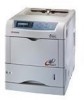
... devices. What's more, the FS-C5020N and FS-C5030N maintain most of developing units and drums. The FS-C5020N/30N however, was intentionally designed to accommodate four sets of their output. Consider These Other Outstanding Features: Small Footprint Most tandem color printers are large in size to be... with 17 and 26 pages per minute Full-Color and Monochrome output speeds respectively for their full-rated speed when duplexing! Kyocera has accomplished this enviable combination with the FS-C5020N and FS-C5030N Color Print Systems. The FS-C5020/30N features 600 x 600 multi-bit ...
... devices. What's more, the FS-C5020N and FS-C5030N maintain most of developing units and drums. The FS-C5020N/30N however, was intentionally designed to accommodate four sets of their output. Consider These Other Outstanding Features: Small Footprint Most tandem color printers are large in size to be... with 17 and 26 pages per minute Full-Color and Monochrome output speeds respectively for their full-rated speed when duplexing! Kyocera has accomplished this enviable combination with the FS-C5020N and FS-C5030N Color Print Systems. The FS-C5020/30N features 600 x 600 multi-bit ...

Service Manual
Page 3
... card (optional)...1-3-10 1-3-4 Installing the network interface card (optional 1-3-11 1-3-5 Installing the hard disk unit (optional 1-3-12 1-4 Maintenance Mode 1-4-1 Service mode ...1-4-1 (1) Executing service mode ...1-4-1 1-4-2 Maintenance ...1-4-18...unit...1-6-10 (1) Detaching and refitting the MP tray feed unit 1-6-10 (2) Detaching and refitting the MP tray feed roller 1-6-11 1-6-5 Developing section...1-6-12 (1) Detaching and refitting the developer unit 1-6-12 1-6-6 Drum section...1-6-13 (1) Detaching and refitting the drum unit 1-6-13 (2) Replacing the LED print head and drum unit...
... card (optional)...1-3-10 1-3-4 Installing the network interface card (optional 1-3-11 1-3-5 Installing the hard disk unit (optional 1-3-12 1-4 Maintenance Mode 1-4-1 Service mode ...1-4-1 (1) Executing service mode ...1-4-1 1-4-2 Maintenance ...1-4-18...unit...1-6-10 (1) Detaching and refitting the MP tray feed unit 1-6-10 (2) Detaching and refitting the MP tray feed roller 1-6-11 1-6-5 Developing section...1-6-12 (1) Detaching and refitting the developer unit 1-6-12 1-6-6 Drum section...1-6-13 (1) Detaching and refitting the drum unit 1-6-13 (2) Replacing the LED print head and drum unit...

Service Manual
Page 4
... ...2-1-5 2-1-2 Developing section...2-1-7 (1) Developer unit ...2-1-7 (2) Touch down developing method ...2-1-9 (3) \Developer drive stop mechanism 2-1-10 2-1-3 Drum section...2-1-11 (1) Drum unit...2-1-11 (2) Waste toner ejecting mechanism ...2-1-14 (3) LED print head ...2-1-15 (4) Main charger unit...2-1-17 2-1-4 Primary transfer section ...2-1-19 (1) Primary transfer unit ...2-1-19 (2) Primary transfer cleaning unit...2-1-21 2-1-5 Secondary transfer and separation section 2-1-24 2-1-6 Fuser section ...2-1-26 (1) Fuser unit (16 ppm printer)...2-1-26 (2) Fuser unit (24...
... ...2-1-5 2-1-2 Developing section...2-1-7 (1) Developer unit ...2-1-7 (2) Touch down developing method ...2-1-9 (3) \Developer drive stop mechanism 2-1-10 2-1-3 Drum section...2-1-11 (1) Drum unit...2-1-11 (2) Waste toner ejecting mechanism ...2-1-14 (3) LED print head ...2-1-15 (4) Main charger unit...2-1-17 2-1-4 Primary transfer section ...2-1-19 (1) Primary transfer unit ...2-1-19 (2) Primary transfer cleaning unit...2-1-21 2-1-5 Secondary transfer and separation section 2-1-24 2-1-6 Fuser section ...2-1-26 (1) Fuser unit (16 ppm printer)...2-1-26 (2) Fuser unit (24...

Service Manual
Page 19
... ppm printer Optional duplexer Paper path (Main unit) Optional paper feeders Paper path (Optional unit) 1. MP tray feed unit 17. Fuser unit 19. Controller box 20. Face-down tray unit (vertical path) 21. Magenta drum unit 5. Feed unit 18. Yellow drum unit 3. Black developer unit 6. Magenta toner container 13. Primary transfer cleaning unit 15. Cyan toner container Figure 1-1-3 12. Black drum unit 2. Cyan developer unit...
... ppm printer Optional duplexer Paper path (Main unit) Optional paper feeders Paper path (Optional unit) 1. MP tray feed unit 17. Fuser unit 19. Controller box 20. Face-down tray unit (vertical path) 21. Magenta drum unit 5. Feed unit 18. Yellow drum unit 3. Black developer unit 6. Magenta toner container 13. Primary transfer cleaning unit 15. Cyan toner container Figure 1-1-3 12. Black drum unit 2. Cyan developer unit...

Service Manual
Page 21
... sunlight or bright lighting. Allow sufficient access for proper operation and maintenance of the machine. Note the following when handling or storing the drum (drum unit). Power supply: 120 V AC (U.S.A./Canada), 220 - 240 V AC (European countries) 4. Ensure that the photo-conductor will not be touched by hands or ... expose the drum surface to strong direct light. • Avoid abrupt changes in a cool, dark place. Developer unit and toner container Store the toner container in temperature and humidity. • Avoid exposure to or may adversely affect the machine or degrade ...
... sunlight or bright lighting. Allow sufficient access for proper operation and maintenance of the machine. Note the following when handling or storing the drum (drum unit). Power supply: 120 V AC (U.S.A./Canada), 220 - 240 V AC (European countries) 4. Ensure that the photo-conductor will not be touched by hands or ... expose the drum surface to strong direct light. • Avoid abrupt changes in a cool, dark place. Developer unit and toner container Store the toner container in temperature and humidity. • Avoid exposure to or may adversely affect the machine or degrade ...

Service Manual
Page 40
... ᕎᕠ Primary transfer unit life counter ᕎᕗ Developing units conuter ᕎᕘ Color print counter ᕎᕙ Maintenance kit counter ᕎᕚ Optional unit software version ᕎᕛ Drum... ID Description /Duplexer/ /Black/Cyan/Magenta/Yellow/ /Black/Cyan/Magenta/Yellow/ /Paper feeder1/Paper feeder 2/Paper feeder 3/Envelope feeder/Duplexer /Black/Cyan/ Magenta/Yellow/ ᕎᕜ LED...
... ᕎᕠ Primary transfer unit life counter ᕎᕗ Developing units conuter ᕎᕘ Color print counter ᕎᕙ Maintenance kit counter ᕎᕚ Optional unit software version ᕎᕛ Drum... ID Description /Duplexer/ /Black/Cyan/Magenta/Yellow/ /Black/Cyan/Magenta/Yellow/ /Paper feeder1/Paper feeder 2/Paper feeder 3/Envelope feeder/Duplexer /Black/Cyan/ Magenta/Yellow/ ᕎᕜ LED...

Service Manual
Page 49
... tray feed roller (See page 1-6-11). Maintenance kit includes the following units: Item Maitenance kit Drum units 4 Black developer unit Yellow developer unit Magenta developer unit Cyan developer unit Primary transfer set (Primary transfer unit and primary transfer cleaning unit) Paper feed unit Fuser unit Ozone filters 2 Feed rollers set 16 ppm printer For European countries For USA/ Canada MK-510 MK-512 DK-510...
... tray feed roller (See page 1-6-11). Maintenance kit includes the following units: Item Maitenance kit Drum units 4 Black developer unit Yellow developer unit Magenta developer unit Cyan developer unit Primary transfer set (Primary transfer unit and primary transfer cleaning unit) Paper feed unit Fuser unit Ozone filters 2 Feed rollers set 16 ppm printer For European countries For USA/ Canada MK-510 MK-512 DK-510...

Service Manual
Page 67
...41. Lump of toner replenishment drive system. Defective harness of the toner sensor 4, defective connection of the connector between black developer unit and the printer main unit or poor contact of toner motor 2. See page 1-6-12. See page 1-6-41. Replace the cyan toner container. See page... sensor 4 inside yellow toner container or defectiveness of the connector with the black developer unit and the printer main unit, if there is not installed. Replace the toner motor 3. Replace the black developer unit. See page 1-6-41. Check the damage of harness of the toner sensor ...
...41. Lump of toner replenishment drive system. Defective harness of the toner sensor 4, defective connection of the connector between black developer unit and the printer main unit or poor contact of toner motor 2. See page 1-6-12. See page 1-6-41. Replace the cyan toner container. See page... sensor 4 inside yellow toner container or defectiveness of the connector with the black developer unit and the printer main unit, if there is not installed. Replace the toner motor 3. Replace the black developer unit. See page 1-6-41. Check the damage of harness of the toner sensor ...

Service Manual
Page 68
... the den- Replace the engine controller PWB (A0004). Replace the magenta developer unit. Replace the cyan developer unit. sity detection signal, judged the nector between cyan developer unit and the printer main unit or poor contact of the connector between engine controller PWB (A0004) the magenta developer magenta developer unit is trouble, remedy or replace. Defective harness of the toner sensor...
... the den- Replace the engine controller PWB (A0004). Replace the magenta developer unit. Replace the cyan developer unit. sity detection signal, judged the nector between cyan developer unit and the printer main unit or poor contact of the connector between engine controller PWB (A0004) the magenta developer magenta developer unit is trouble, remedy or replace. Defective harness of the toner sensor...

Service Manual
Page 69
... 2F3/2F4-3.0 Code 7404 Contents Yellow developer unit non- Replace the drum PWB 4 (KP-972). Defective harness (S02869) between yellow developer unit and the printer main unit or poor contact of the connector with the printer specification. Remarks Causes Check procedures/corrective... measures Defective harness of the toner sensor 3, defective connection of the connector between engine controller PWB (A0004) and LED ...
... 2F3/2F4-3.0 Code 7404 Contents Yellow developer unit non- Replace the drum PWB 4 (KP-972). Defective harness (S02869) between yellow developer unit and the printer main unit or poor contact of the connector with the printer specification. Remarks Causes Check procedures/corrective... measures Defective harness of the toner sensor 3, defective connection of the connector between engine controller PWB (A0004) and LED ...

Service Manual
Page 98
While releasing two release levers and then remove the developer unit. (Use the same procedure for other developers.) Release lever Release lever Connector Developer unit (Cyan) (Black) (Magenta) (Yellow) Figure 1-6-14 1-6-12 Remove the one connector. 3. Open the top cover. 2. 2F3/2F4 1-6-5 Developing section (1) Detaching and refitting the developer unit Procedure 1.
While releasing two release levers and then remove the developer unit. (Use the same procedure for other developers.) Release lever Release lever Connector Developer unit (Cyan) (Black) (Magenta) (Yellow) Figure 1-6-14 1-6-12 Remove the one connector. 3. Open the top cover. 2. 2F3/2F4 1-6-5 Developing section (1) Detaching and refitting the developer unit Procedure 1.

Service Manual
Page 99
...connector FFC connector Connector FFC-a FFC-b (blue color marking) FFC: Flexible Flat Cable Figure 1-6-15 1-6-13 Remove the developer unit (See previous page). 2. Refer to check that the printer operates properly and then turn on the printer after replacing either one. Replace the other and ...turn on the printer to self-diagnostic code 9530 (See page ...
...connector FFC connector Connector FFC-a FFC-b (blue color marking) FFC: Flexible Flat Cable Figure 1-6-15 1-6-13 Remove the developer unit (See previous page). 2. Refer to check that the printer operates properly and then turn on the printer after replacing either one. Replace the other and ...turn on the printer to self-diagnostic code 9530 (See page ...

Service Manual
Page 101
... (blue) 1 With conductive tape (for black) LED print head Kit Item ᕇ LED print head ᕄ FFC (white) ᕅ FFC (blue) ᕆ FFC (blue) 16 ppm 24 ppm printer printer LK-510 LK-520 Remark 1 1 1 1 1 1 1 With conductive tape (for the color to be replaced. 5. Remove the toner containers and developer units. 4. Open the top cover. 3. Remove two...
... (blue) 1 With conductive tape (for black) LED print head Kit Item ᕇ LED print head ᕄ FFC (white) ᕅ FFC (blue) ᕆ FFC (blue) 16 ppm 24 ppm printer printer LK-510 LK-520 Remark 1 1 1 1 1 1 1 With conductive tape (for the color to be replaced. 5. Remove the toner containers and developer units. 4. Open the top cover. 3. Remove two...

Service Manual
Page 107
...data stored in the EEPROM mounted on the LED print head for optimizing the LED print head performance. Damage of the operation panel. 28. ers to the LED print head (Step 12). Note: After the LED print head has been replaced, the printer requires approximately 30 seconds until it gets ready.... If test print is required because the printer needs to the printer (Step 23). Refit the developer units and toner contain- Close the top...
...data stored in the EEPROM mounted on the LED print head for optimizing the LED print head performance. Damage of the operation panel. 28. ers to the LED print head (Step 12). Note: After the LED print head has been replaced, the printer requires approximately 30 seconds until it gets ready.... If test print is required because the printer needs to the printer (Step 23). Refit the developer units and toner contain- Close the top...

Service Manual
Page 149
2F3/2F4 2-1-2 Developing section (1) Developer unit Developing section is composed of mixer screw, developing blade, developing magnet roller and, developing sleeve. ᕉ ᕇ ᕆ ᕈ ᕅ ᕄ ᕃ Figure 2-1-10 Developer unit (1) Developing sleeve (2) Developing magnet roller (3) Doctor blade (4) Mixer screw B (5) Mixer screw A (6) Developer case (7) Developer lid Developer case Toner sensor Mixer screw B Mixer screw A Developing magnet roller Doctor blade Developing sleeve Figure 2-1-11 Developer unit 2-1-7
2F3/2F4 2-1-2 Developing section (1) Developer unit Developing section is composed of mixer screw, developing blade, developing magnet roller and, developing sleeve. ᕉ ᕇ ᕆ ᕈ ᕅ ᕄ ᕃ Figure 2-1-10 Developer unit (1) Developing sleeve (2) Developing magnet roller (3) Doctor blade (4) Mixer screw B (5) Mixer screw A (6) Developer case (7) Developer lid Developer case Toner sensor Mixer screw B Mixer screw A Developing magnet roller Doctor blade Developing sleeve Figure 2-1-11 Developer unit 2-1-7

Service Manual
Page 151
...continuously agitated by means of both mono-component system and dual component system. Developer unit Toner hopper Doctor blade : 0.50 to each other by means of 0.40 millimeters. The developing magnet roller is comprised of a magnet and a sleeve which is a... mm LED print head Main charger Mixer screw A Toner Carrier Mixer screw B Developing magnet roller ᕃ ᕄ N3 N2 S2 S1 N1 Drum Developing S magnet roller N S Developing sleeve Magnetic brush Developing sleeve Developing sleeve Figure 2-1-13 ᕅ Drum 70 µm 2-1-9 The developing magnet roller...
...continuously agitated by means of both mono-component system and dual component system. Developer unit Toner hopper Doctor blade : 0.50 to each other by means of 0.40 millimeters. The developing magnet roller is comprised of a magnet and a sleeve which is a... mm LED print head Main charger Mixer screw A Toner Carrier Mixer screw B Developing magnet roller ᕃ ᕄ N3 N2 S2 S1 N1 Drum Developing S magnet roller N S Developing sleeve Magnetic brush Developing sleeve Developing sleeve Figure 2-1-13 ᕅ Drum 70 µm 2-1-9 The developing magnet roller...

Service Manual
Page 152
... the time of monochrome printing. But idle gear which transmits a drive to a black developer is being fixed to main drive unit, although a drive is transmitted to developer gear (K3) and a black development unit always drives. Color printing Idle plate lever Cam lever Developer drive stop motor with each idle gear (K2, Y2, C2, M2), so that the...
... the time of monochrome printing. But idle gear which transmits a drive to a black developer is being fixed to main drive unit, although a drive is transmitted to developer gear (K3) and a black development unit always drives. Color printing Idle plate lever Cam lever Developer drive stop motor with each idle gear (K2, Y2, C2, M2), so that the...

Service Manual
Page 153
... the eraser lamp. The electrostatic latent image is discharged by the developer unit and transferred onto the primary transfer belt in cyan, magenta, yellow, and black colors. The toner remaining on the drum is scraped off by the cleaning blade and driven outside by LED hits the charged drum, the electrostatic latent image is...
... the eraser lamp. The electrostatic latent image is discharged by the developer unit and transferred onto the primary transfer belt in cyan, magenta, yellow, and black colors. The toner remaining on the drum is scraped off by the cleaning blade and driven outside by LED hits the charged drum, the electrostatic latent image is...

Service Manual
Page 175
... color drum unit. 12. (2) Drum unit, developer unit and fuser unit ᕄ ᕃ ᕇ ᕍᕗ ᕅᕊ ᕈ 2F3/2F4 ᕍᕠ FUSER UNIT ᕋ (16 ppm printer) ᕍᕘ ᕍᕙ ᕍᕚ ᕆ DRUM UNIT DEVELOPER UNIT ᕉ ᕍᕛ ᕍᕠ ᕅ ᕈ ᕍᕘ FUSER UNIT (24 ppm printer) Figure 2-2-2 Drum unit, developer unit and fuser unit 1. LED print head 1, 2, 3, 4 LED print head 1 (magenta), LED...
... color drum unit. 12. (2) Drum unit, developer unit and fuser unit ᕄ ᕃ ᕇ ᕍᕗ ᕅᕊ ᕈ 2F3/2F4 ᕍᕠ FUSER UNIT ᕋ (16 ppm printer) ᕍᕘ ᕍᕙ ᕍᕚ ᕆ DRUM UNIT DEVELOPER UNIT ᕉ ᕍᕛ ᕍᕠ ᕅ ᕈ ᕍᕘ FUSER UNIT (24 ppm printer) Figure 2-2-2 Drum unit, developer unit and fuser unit 1. LED print head 1, 2, 3, 4 LED print head 1 (magenta), LED...


