FS-C5020/C5030 Operation Guide (Basic Edition)
Page 35
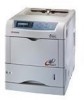
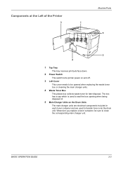
... used to seal the box opening when being disposed of the Printer 3 Machine Parts 1 5 2 4 1 Top Tray This tray receives printouts face down. 2 Power Switch This switch turns printer power on the Drum Units The main charger units are electrical components included in each toner container and are used... to clean the corresponding main charger unit. Components at the Left of . 5 Main Charger Units on and off. 3 Left Cover This...
... used to seal the box opening when being disposed of the Printer 3 Machine Parts 1 5 2 4 1 Top Tray This tray receives printouts face down. 2 Power Switch This switch turns printer power on the Drum Units The main charger units are electrical components included in each toner container and are used... to clean the corresponding main charger unit. Components at the Left of . 5 Main Charger Units on and off. 3 Left Cover This...

Service Manual
Page 3
... secondary transfer roller 1-6-9 1-6-4 MP tray feed unit...1-6-10 (1) Detaching and refitting the MP tray feed unit 1-6-10 (2) Detaching and refitting the MP tray feed roller 1-6-11 1-6-5 Developing section...1-6-12 (1) Detaching and refitting the developer unit 1-6-12 1-6-6 Drum section...1-6-13 (1) Detaching and refitting the drum unit 1-6-13 (2) Replacing the LED print head and drum unit 1-6-15 1-6-7 Primary transfer section ...1-6-22
... secondary transfer roller 1-6-9 1-6-4 MP tray feed unit...1-6-10 (1) Detaching and refitting the MP tray feed unit 1-6-10 (2) Detaching and refitting the MP tray feed roller 1-6-11 1-6-5 Developing section...1-6-12 (1) Detaching and refitting the developer unit 1-6-12 1-6-6 Drum section...1-6-13 (1) Detaching and refitting the drum unit 1-6-13 (2) Replacing the LED print head and drum unit 1-6-15 1-6-7 Primary transfer section ...1-6-22

Service Manual
Page 4
... drive stop mechanism 2-1-10 2-1-3 Drum section...2-1-11 (1) Drum unit...2-1-11 (2) Waste toner ejecting mechanism ...2-1-14 (3) LED print head ...2-1-15 (4) Main charger unit...2-1-17 2-1-4 Primary transfer section ...2-1-19 (1) Primary transfer unit ...2-1-19 (2) Primary transfer cleaning unit...2-1-21 2-1-5 Secondary transfer and separation section 2-1-24 2-1-6 Fuser section ...2-1-26 (1) Fuser unit (16 ppm printer)...2-1-26 (2) Fuser unit (24 ppm printer)...2-1-28 2-2 Electrical Parts Layout 2-2-1 Electrical...
... drive stop mechanism 2-1-10 2-1-3 Drum section...2-1-11 (1) Drum unit...2-1-11 (2) Waste toner ejecting mechanism ...2-1-14 (3) LED print head ...2-1-15 (4) Main charger unit...2-1-17 2-1-4 Primary transfer section ...2-1-19 (1) Primary transfer unit ...2-1-19 (2) Primary transfer cleaning unit...2-1-21 2-1-5 Secondary transfer and separation section 2-1-24 2-1-6 Fuser section ...2-1-26 (1) Fuser unit (16 ppm printer)...2-1-26 (2) Fuser unit (24 ppm printer)...2-1-28 2-2 Electrical Parts Layout 2-2-1 Electrical...

Service Manual
Page 19
...;ᕞ 24 ppm printer ᕍᕞ 16 ppm printer Optional duplexer Paper path (Main unit) Optional paper feeders Paper path (Optional unit) 1. Cyan drum unit 4. Cyan developer unit 8. Controller box 20. Yellow developer unit 7. Primary transfer cleaning unit 15. Paper cassette 1-1-7 Black drum unit 2. Magenta toner container 13. Feed unit 18. Yellow toner container 11. Fuser unit 19. Yellow drum unit 3. Magenta drum unit 5. Black toner container...
...;ᕞ 24 ppm printer ᕍᕞ 16 ppm printer Optional duplexer Paper path (Main unit) Optional paper feeders Paper path (Optional unit) 1. Cyan drum unit 4. Cyan developer unit 8. Controller box 20. Yellow developer unit 7. Primary transfer cleaning unit 15. Paper cassette 1-1-7 Black drum unit 2. Magenta toner container 13. Feed unit 18. Yellow toner container 11. Fuser unit 19. Yellow drum unit 3. Magenta drum unit 5. Black toner container...

Service Manual
Page 21
... by hands or stained with good ventilation. 6. Power supply: 120 V AC (U.S.A./Canada), 220 - 240 V AC (European countries) 4. Note the following when handling or storing the drum (drum unit). Allow sufficient access for proper operation and maintenance of the machine. Power source frequency: 50 Hz ±2%/60 Hz ±2% 5. Developer...
... by hands or stained with good ventilation. 6. Power supply: 120 V AC (U.S.A./Canada), 220 - 240 V AC (European countries) 4. Note the following when handling or storing the drum (drum unit). Allow sufficient access for proper operation and maintenance of the machine. Power source frequency: 50 Hz ±2%/60 Hz ±2% 5. Developer...

Service Manual
Page 48
2F3/2F4 Service items >>Color Calibration >>Print Test Page Execution of color calibration Description Description Executing the density of four colors. Purpose To carry out color calibration manually besides it can be carried out automatically each time the printer is printed. Purpose To check the activation of the developer and drum units of color using. Press the ENTER key...
2F3/2F4 Service items >>Color Calibration >>Print Test Page Execution of color calibration Description Description Executing the density of four colors. Purpose To carry out color calibration manually besides it can be carried out automatically each time the printer is printed. Purpose To check the activation of the developer and drum units of color using. Press the ENTER key...

Service Manual
Page 49
... (See page 1-6-11). This may be used to the new drum unit (See page 1-6-15). 3. Remove the LED print head from each component is displayed. 2. is reset immediately. Replace the fuser unit (See page 1-6-25 or 1-6-32). 6. Procedure Enter the service...includes the following units: Item Maitenance kit Drum units 4 Black developer unit Yellow developer unit Magenta developer unit Cyan developer unit Primary transfer set (Primary transfer unit and primary transfer cleaning unit) Paper feed unit Fuser unit Ozone filters 2 Feed rollers set 16 ppm printer For European countries ...
... (See page 1-6-11). This may be used to the new drum unit (See page 1-6-15). 3. Remove the LED print head from each component is displayed. 2. is reset immediately. Replace the fuser unit (See page 1-6-25 or 1-6-32). 6. Procedure Enter the service...includes the following units: Item Maitenance kit Drum units 4 Black developer unit Yellow developer unit Magenta developer unit Cyan developer unit Primary transfer set (Primary transfer unit and primary transfer cleaning unit) Paper feed unit Fuser unit Ozone filters 2 Feed rollers set 16 ppm printer For European countries ...

Service Manual
Page 57
... engine controller PWB (A0004). Install the compatible LED print head to the black drum unit. See page 1-6-44. (A0008). See page 1-6-15. LED print head 2 (EEPROM) communication error [cyan drum unit] • The LED print head 2 (EEPROM) of the black drum unit does not communicate with the printer specification. Defective LED print head 2. LED print heads relay PWB (A0008), or poor contact...
... engine controller PWB (A0004). Install the compatible LED print head to the black drum unit. See page 1-6-44. (A0008). See page 1-6-15. LED print head 2 (EEPROM) communication error [cyan drum unit] • The LED print head 2 (EEPROM) of the black drum unit does not communicate with the printer specification. Defective LED print head 2. LED print heads relay PWB (A0008), or poor contact...

Service Manual
Page 58
... Contents Causes Remarks Check procedures/corrective measures LED print head 1 (EEPROM) communication error [magenta drum unit] • The LED print head 1 (EEPROM) of the magenta drum unit does not communicate with the magenta drum unit and the printer main unit, check the continuity of the FFCs (...S03011) between (S02869), check the insertion of YC3 of the yellow drun unit does not communicate with the printer specification. LED print head 3 (EEPROM) communication error [yellow drum unit] • The LED print head 3 (EEPROM) of the engine controller engine controller PWB (...
... Contents Causes Remarks Check procedures/corrective measures LED print head 1 (EEPROM) communication error [magenta drum unit] • The LED print head 1 (EEPROM) of the magenta drum unit does not communicate with the magenta drum unit and the printer main unit, check the continuity of the FFCs (...S03011) between (S02869), check the insertion of YC3 of the yellow drun unit does not communicate with the printer specification. LED print head 3 (EEPROM) communication error [yellow drum unit] • The LED print head 3 (EEPROM) of the engine controller engine controller PWB (...

Service Manual
Page 59
...41. Refer to the paper feeder PF-60's service manual. Replace the engine controller PWB (A0004). See page 1-6-41. Eraser lamp 4 error (black drum unit) • The eraser lamp 4 [PWB] (KP-1090) of the engine controller PWB (A0004), if there is trouble, remedy or replace. Defective...connection YC3 connector of the black drum unit does not communicate with the engine controller PWB (A0004) normally. Refer to the paper feeder PF-60's service manual. See page 1-6-41. Defective harness (S02868) between engine controller PWB (A0004) and LED print heads relay PWB (A0008),...
...41. Refer to the paper feeder PF-60's service manual. Replace the engine controller PWB (A0004). See page 1-6-41. Eraser lamp 4 error (black drum unit) • The eraser lamp 4 [PWB] (KP-1090) of the engine controller PWB (A0004), if there is trouble, remedy or replace. Defective...connection YC3 connector of the black drum unit does not communicate with the engine controller PWB (A0004) normally. Refer to the paper feeder PF-60's service manual. See page 1-6-41. Defective harness (S02868) between engine controller PWB (A0004) and LED print heads relay PWB (A0008),...

Service Manual
Page 60
Replace the eraser lamp 2 [PWB] (KP1090). See page 1-6- Defective LED print Replace the LED print heads relay PWB heads relay PWB (A0008). Defective drum Replace the cyan drum unit. Check the connection of the YC402 connector of the drum PWB 2 (KP-972), if there is trouble, remedy or replace. PWB... measures Eraser lamp 2 error (cyan drum unit) • The eraser lamp 2 [PWB] (KP-1090) of the engine controller PWB (A0004), if there is trouble, remedy or replace. Defective harness (S02868) between engine controller PWB (A0004) and LED print heads relay PWB (A0008), or...
Replace the eraser lamp 2 [PWB] (KP1090). See page 1-6- Defective LED print Replace the LED print heads relay PWB heads relay PWB (A0008). Defective drum Replace the cyan drum unit. Check the connection of the YC402 connector of the drum PWB 2 (KP-972), if there is trouble, remedy or replace. PWB... measures Eraser lamp 2 error (cyan drum unit) • The eraser lamp 2 [PWB] (KP-1090) of the engine controller PWB (A0004), if there is trouble, remedy or replace. Defective harness (S02868) between engine controller PWB (A0004) and LED print heads relay PWB (A0008), or...

Service Manual
Page 61
... 1 (KP-972), if there is trouble, remedy or replace. Defective LED print Replace the LED print heads relay PWB heads relay PWB (A0008). 2F3/2F4 Code 5303 Contents Causes Remarks Check procedures/corrective measures Eraser lamp 1 error (magenta drum unit) • The eraser lamp 1 [PWB] (KP-1090) of the connector terminals. See page PWB...
... 1 (KP-972), if there is trouble, remedy or replace. Defective LED print Replace the LED print heads relay PWB heads relay PWB (A0008). 2F3/2F4 Code 5303 Contents Causes Remarks Check procedures/corrective measures Eraser lamp 1 error (magenta drum unit) • The eraser lamp 1 [PWB] (KP-1090) of the connector terminals. See page PWB...

Service Manual
Page 62
...-972), if there is trouble, remedy or replace. 2F3/2F4 Code 5304 Contents Causes Remarks Check procedures/corrective measures Eraser lamp 3 error (yellow drum unit) • The eraser lamp 3 [PWB] (KP-1090) of the connector terminals. Defective eraser lamp 3 [PWB] (KP1090). Replace the engine...engine controller PWB (A0004). Defective LED print Replace the LED print heads relay PWB heads relay PWB (A0008). Defective harness (S02868) between engine controller PWB (A0004) and LED print heads relay PWB (A0008), or poor contact of the yellow drum unit does not communicate with the engine...
...-972), if there is trouble, remedy or replace. 2F3/2F4 Code 5304 Contents Causes Remarks Check procedures/corrective measures Eraser lamp 3 error (yellow drum unit) • The eraser lamp 3 [PWB] (KP-1090) of the connector terminals. Defective eraser lamp 3 [PWB] (KP1090). Replace the engine...engine controller PWB (A0004). Defective LED print Replace the LED print heads relay PWB heads relay PWB (A0008). Defective harness (S02868) between engine controller PWB (A0004) and LED print heads relay PWB (A0008), or poor contact of the yellow drum unit does not communicate with the engine...

Service Manual
Page 69
... of the connector between yellow developer unit and the printer main unit or poor contact of the connector terminals. The incompatible drum unit is not installed. Defective harness between engine controller PWB (A0004) and LED print heads relay PWB (A0008) ...drum PWB 4 (KP-972). Defective LED print Replace the LED print heads relay PWB heads relay PWB (A0008). installing error • The toner sensor 3 inside the black drum unit does not communicate normally. Installing the drum unit, which is incompatible with the yellow developer unit and the printer main unit...
... of the connector between yellow developer unit and the printer main unit or poor contact of the connector terminals. The incompatible drum unit is not installed. Defective harness between engine controller PWB (A0004) and LED print heads relay PWB (A0008) ...drum PWB 4 (KP-972). Defective LED print Replace the LED print heads relay PWB heads relay PWB (A0008). installing error • The toner sensor 3 inside the black drum unit does not communicate normally. Installing the drum unit, which is incompatible with the yellow developer unit and the printer main unit...

Service Manual
Page 70
... the engine controller PWB (A0004), if there is trouble, remedy or replace. 1-5-18 The incompatible drum unit is incompatible with the printer specification. Install the compatible drum unit to the printer. Defective engine controller PWB (A0004). Defective LED print Replace the LED print heads relay PWB heads relay PWB (A0008). Defective harness (S02869) between engine controller PWB (A0004...
... the engine controller PWB (A0004), if there is trouble, remedy or replace. 1-5-18 The incompatible drum unit is incompatible with the printer specification. Install the compatible drum unit to the printer. Defective engine controller PWB (A0004). Defective LED print Replace the LED print heads relay PWB heads relay PWB (A0008). Defective harness (S02869) between engine controller PWB (A0004...

Service Manual
Page 71
... to replace one by reverting the engine controller and the PWB (A0004) and drum unit to the printer. 2F3/2F4-3.0 Code 7414 7600 9530 Contents Causes Remarks Check procedures/corrective measures Yellow drum unit non- Defective harness between engine controller PWB (A0004) and LED print heads relay PWB (A0008) or poor contact of the connector terminals...
... to replace one by reverting the engine controller and the PWB (A0004) and drum unit to the printer. 2F3/2F4-3.0 Code 7414 7600 9530 Contents Causes Remarks Check procedures/corrective measures Yellow drum unit non- Defective harness between engine controller PWB (A0004) and LED print heads relay PWB (A0008) or poor contact of the connector terminals...

Service Manual
Page 79
... page 1-4-14. Clean the SELFOC lens of LED print head by using lens cleaner. *1: 16 ppm printer, *2: 24 ppm printer 1-5-27 Defective developing bias output. 2. B. C. Replace the main controller PWB (A0010*1/A0011*2). Replace the drum unit. A. Perform the color calibration of the toner ID sensor. Check the four colors of LED print head. Defective bias high voltage PWB...
... page 1-4-14. Clean the SELFOC lens of LED print head by using lens cleaner. *1: 16 ppm printer, *2: 24 ppm printer 1-5-27 Defective developing bias output. 2. B. C. Replace the main controller PWB (A0010*1/A0011*2). Replace the drum unit. A. Perform the color calibration of the toner ID sensor. Check the four colors of LED print head. Defective bias high voltage PWB...

Service Manual
Page 80
... test print of service mode. Defective engine controller PWB. Defective main controller PWB. Defective drum unit. Replace the drum unit. A. The printer environment considerably changed since an automatic calibration was made. Perform the color calibration of service mode. 2F3/2F4 (6) The background is colored. Causes Check procedures/corrective measures 1. B. See page 1-6-41. Replace the main controller PWB...
... test print of service mode. Defective engine controller PWB. Defective main controller PWB. Defective drum unit. Replace the drum unit. A. The printer environment considerably changed since an automatic calibration was made. Perform the color calibration of service mode. 2F3/2F4 (6) The background is colored. Causes Check procedures/corrective measures 1. B. See page 1-6-41. Replace the main controller PWB...

Service Manual
Page 82
... output terminal of the main charger wire cleaner. 3. Poor contact of developing bias terminal of main charger unit. 2. Replace the drum unit. Deformed or worn cleaning blade in the drum unit. 5. Dirty main charger wire. 2. Dirty or flawed drum. Flawed drum. 4. See page 1-6-13. Poor contact of output terminal of developer. Causes 1. See page 1-6-12. 1-5-30 Poor...
... output terminal of the main charger wire cleaner. 3. Poor contact of developing bias terminal of main charger unit. 2. Replace the drum unit. Deformed or worn cleaning blade in the drum unit. 5. Dirty main charger wire. 2. Dirty or flawed drum. Flawed drum. 4. See page 1-6-13. Poor contact of output terminal of developer. Causes 1. See page 1-6-12. 1-5-30 Poor...

Service Manual
Page 83
... installation of the primary transfer cleaning unit. 4. Dirty or flawed drum. 2. Deformed or worn cleaning blade in the drum unit. 3. See page 1-4-18. *1: 16 ppm printer, *2: 24 ppm printer (11) The leading edge of the primary transfer cleaning unit. 4. Replace the developer. Dirty or flawed drum. 2. Flawed developing sleeve roller. 5. Replace the drum unit. Clean the heat roller and press...
... installation of the primary transfer cleaning unit. 4. Dirty or flawed drum. 2. Deformed or worn cleaning blade in the drum unit. 3. See page 1-4-18. *1: 16 ppm printer, *2: 24 ppm printer (11) The leading edge of the primary transfer cleaning unit. 4. Replace the developer. Dirty or flawed drum. 2. Flawed developing sleeve roller. 5. Replace the drum unit. Clean the heat roller and press...


