FS-1120D/1320D Operation Guide Rev-1
Page 21
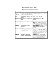
... on page 3-9. Conventions in a plastic bag and ship them separately from the carton until you ship the printer, remove and pack the developer unit and drum unit in This Guide This manual uses the following conventions. IMPORTANT Take care not to denote operation panel Printing resumes when [GO] is keys. Bracket...
... on page 3-9. Conventions in a plastic bag and ship them separately from the carton until you ship the printer, remove and pack the developer unit and drum unit in This Guide This manual uses the following conventions. IMPORTANT Take care not to denote operation panel Printing resumes when [GO] is keys. Bracket...
FS-1120D/1320D Operation Guide Rev-1
Page 35
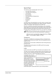
... transparency can be loaded at a time. One label can be loaded at a time. Label paper has a structure comprising of pressure-sensitive adhesives. Due to the drum or rollers will be fed to the MP Tray. Half speed mode is satisfactory. The adhesive layer consists of three layers, as shown in the...
... transparency can be loaded at a time. One label can be loaded at a time. Label paper has a structure comprising of pressure-sensitive adhesives. Due to the drum or rollers will be fed to the MP Tray. Half speed mode is satisfactory. The adhesive layer consists of three layers, as shown in the...
FS-1120D/1320D Operation Guide Rev-1
Page 67
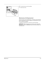
To replace the maintenance kit, contact your service technician. IMPORTANT When the waste toner in the drum unit is printed indicating that the maintenance kit should be replaced immediately. 6 Turn the lock lever to the lock position. 7 Close the top cover. Replace the maintenance kit. The maintenance kit must then be replaced. Maintenance 4-5 Maintenance Kit Replacement When the machine prints 100,000 pages, a message is almost full, [Attention] indicator and [Toner] indicator are flashing.
To replace the maintenance kit, contact your service technician. IMPORTANT When the waste toner in the drum unit is printed indicating that the maintenance kit should be replaced immediately. 6 Turn the lock lever to the lock position. 7 Close the top cover. Replace the maintenance kit. The maintenance kit must then be replaced. Maintenance 4-5 Maintenance Kit Replacement When the machine prints 100,000 pages, a message is almost full, [Attention] indicator and [Toner] indicator are flashing.
FS-1120D/1320D Operation Guide Rev-1
Page 68
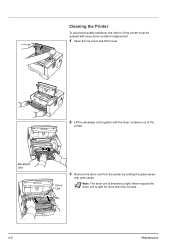
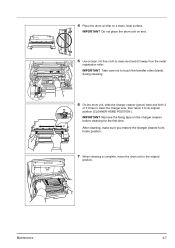
Note The drum unit is sensitive to light for more than five minutes. 4-6 Maintenance Developer Unit Drum Unit 3 Remove the drum unit from the printer by holding the green levers with the toner container out of the printer. Never expose the drum unit to light. Cleaning the Printer To avoid print quality problems, the interior of the printer must be cleaned with every toner container replacement. 1 Open the top cover and front cover. 2 Lift the developer unit together with both hands.
Note The drum unit is sensitive to light for more than five minutes. 4-6 Maintenance Developer Unit Drum Unit 3 Remove the drum unit from the printer by holding the green levers with the toner container out of the printer. Never expose the drum unit to light. Cleaning the Printer To avoid print quality problems, the interior of the printer must be cleaned with every toner container replacement. 1 Open the top cover and front cover. 2 Lift the developer unit together with both hands.
FS-1120D/1320D Operation Guide Rev-1
Page 69
...Maintenance 4-7 IMPORTANT Remove the fixing tape on a clean, level surface. IMPORTANT Take care not to touch the transfer roller (black) during cleaning. 6 On the drum unit, slide the charger cleaner (green) back and forth 2 or 3 times to clean the charger wire, then return it to its home position. 7 ...When cleaning is complete, return the drum unit to clean dust and dirt away from the metal registration roller. 4 Place the drum unit flat on the charger cleaner before cleaning for the first time.
...Maintenance 4-7 IMPORTANT Remove the fixing tape on a clean, level surface. IMPORTANT Take care not to touch the transfer roller (black) during cleaning. 6 On the drum unit, slide the charger cleaner (green) back and forth 2 or 3 times to clean the charger wire, then return it to its home position. 7 ...When cleaning is complete, return the drum unit to clean dust and dirt away from the metal registration roller. 4 Place the drum unit flat on the charger cleaner before cleaning for the first time.
FS-1120D/1320D Operation Guide Rev-1
Page 71
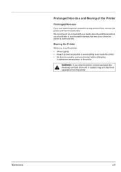
... of the printer. We recommend you consult with your dealer about the additional actions you ship the printer, remove and pack the developer unit and drum unit in a plastic bag and ship them separately from the wall outlet. WARNING If you should take to consult a service technician before attempting longdistance transportation...
... of the printer. We recommend you consult with your dealer about the additional actions you ship the printer, remove and pack the developer unit and drum unit in a plastic bag and ship them separately from the wall outlet. WARNING If you should take to consult a service technician before attempting longdistance transportation...
FS-1120D/1320D Operation Guide Rev-1
Page 75
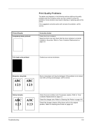
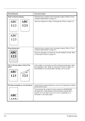
.... Open the front cover and check that the toner container is correctly installed in the printer. Dropouts, stray dots Drum or developer unit may require cleaning or replacing parts of the drum unit is not solved even after printing several pages, call for service. Vertical streaks Troubleshooting Check the toner container and...
.... Open the front cover and check that the toner container is correctly installed in the printer. Dropouts, stray dots Drum or developer unit may require cleaning or replacing parts of the drum unit is not solved even after printing several pages, call for service. Vertical streaks Troubleshooting Check the toner container and...
FS-1120D/1320D Operation Guide Rev-1
Page 76
... to Toner Container Replacement on the top edge or back of position Check that the printing settings are installed correctly. Check the developer unit and drum unit are correct in a parameter to Toner Container Replacement on page 4-6. Printing incomplete or out of the paper If the problem is not solved after...
... to Toner Container Replacement on the top edge or back of position Check that the printing settings are installed correctly. Check the developer unit and drum unit are correct in a parameter to Toner Container Replacement on page 4-6. Printing incomplete or out of the paper If the problem is not solved after...
FS-1120D/1320D Operation Guide Rev-1
Page 87
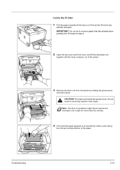
Inside the Printer 1 Pull the paper cassette all the way out of the printer. 3 Remove the drum unit from the printer by rollers, pull it may result in burn injury. Note The drum is hot. Troubleshooting 5-15 Remove any partially fed paper. Do not touch it, as it along the normal running direction...
Inside the Printer 1 Pull the paper cassette all the way out of the printer. 3 Remove the drum unit from the printer by rollers, pull it may result in burn injury. Note The drum is hot. Troubleshooting 5-15 Remove any partially fed paper. Do not touch it, as it along the normal running direction...
FS-1120D/1320D Operation Guide Rev-1
Page 88
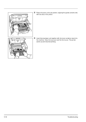
Close the top cover and the front cover. The printer warms up and resumes printing. 5-16 Troubleshooting 5 Return the drum unit to its position, aligning the guides at both ends with the slots in the printer. 6 Insert the developer unit together with the toner container, back into the machine.
Close the top cover and the front cover. The printer warms up and resumes printing. 5-16 Troubleshooting 5 Return the drum unit to its position, aligning the guides at both ends with the slots in the printer. 6 Insert the developer unit together with the toner container, back into the machine.
FS-1120D/1320D Operation Guide Rev-1
Page 105
... rear of the printer 1-3 Connection power cord 3-2 USB cable 3-2 Custom mode installation method 3-5 D Data indicator operation panel 1-4 Developer unit clearing paper jams 5-15 maintenance 4-6 DIMM 6-2 Drum unit clearing paper jams 5-15 maintenance 4-6 Duplexer clearing paper jams 5-14 E Energy Star program xii Envelope 2-8 Environmental standard requirements 7-4 Error indication indicators 5-10 Expansion memory...
... rear of the printer 1-3 Connection power cord 3-2 USB cable 3-2 Custom mode installation method 3-5 D Data indicator operation panel 1-4 Developer unit clearing paper jams 5-15 maintenance 4-6 DIMM 6-2 Drum unit clearing paper jams 5-15 maintenance 4-6 Duplexer clearing paper jams 5-14 E Energy Star program xii Envelope 2-8 Environmental standard requirements 7-4 Error indication indicators 5-10 Expansion memory...

Service Manual
Page 9
... wires that wires will not be present on high-voltage components when removing them; it to spill. Miscellaneous WARNING • Never attempt to heat the drum or expose it may be seen coming from the copier, remove the power plug from the copier except for routine replacement • Do not pull...
... wires that wires will not be present on high-voltage components when removing them; it to spill. Miscellaneous WARNING • Never attempt to heat the drum or expose it may be seen coming from the copier, remove the power plug from the copier except for routine replacement • Do not pull...

Service Manual
Page 11
... the right edge (scanning start position 1-4-13 1-4-4 Electric problems ...1-4-14 1-4-5 Mechanical problems ...1-4-16 1-5 Assembly and Disassembly 1-5-1 Precautions for assembly and disassembly 1-5-1 (1) Precautions ...1-5-1 (2) Drum...1-5-1 (3) Toner container ...1-5-1 (4) How to tell a genuine Kyocera Mita toner container 1-5-2 1-5-2 Outer covers ...1-5-3 (1) Detaching and refitting the top cover 1-5-3 (2) Detaching and refitting the right and left covers 1-5-4 1-5-3 Paper feed section...
... the right edge (scanning start position 1-4-13 1-4-4 Electric problems ...1-4-14 1-4-5 Mechanical problems ...1-4-16 1-5 Assembly and Disassembly 1-5-1 Precautions for assembly and disassembly 1-5-1 (1) Precautions ...1-5-1 (2) Drum...1-5-1 (3) Toner container ...1-5-1 (4) How to tell a genuine Kyocera Mita toner container 1-5-2 1-5-2 Outer covers ...1-5-3 (1) Detaching and refitting the top cover 1-5-3 (2) Detaching and refitting the right and left covers 1-5-4 1-5-3 Paper feed section...

Service Manual
Page 12
... ...1-6-1 (1) Downloading the firmware from the memory card 1-6-2 2-1 Mechanical Construction 2-1-1 Paper feed/conveying section...2-1-1 (1) Cassette paper feed section...2-1-1 (2) MP tray paper feed section ...2-1-2 (3) Paper conveying section ...2-1-3 2-1-2 Drum section...2-1-4 (1) Drum section ...2-1-4 (2) Main charger unit...2-1-5 2-1-3 Expose section...2-1-6 (1) Laser scanner unit...2-1-6 2-1-4 Developing section...2-1-8 2-1-5 Transfer/separation section ...2-1-9 2-1-6 Cleaning section ...2-1-10 2-1-7 Fuser section ...2-1-11 2-1-8 Paper exit section ...2-1-13...
... ...1-6-1 (1) Downloading the firmware from the memory card 1-6-2 2-1 Mechanical Construction 2-1-1 Paper feed/conveying section...2-1-1 (1) Cassette paper feed section...2-1-1 (2) MP tray paper feed section ...2-1-2 (3) Paper conveying section ...2-1-3 2-1-2 Drum section...2-1-4 (1) Drum section ...2-1-4 (2) Main charger unit...2-1-5 2-1-3 Expose section...2-1-6 (1) Laser scanner unit...2-1-6 2-1-4 Developing section...2-1-8 2-1-5 Transfer/separation section ...2-1-9 2-1-6 Cleaning section ...2-1-10 2-1-7 Fuser section ...2-1-11 2-1-8 Paper exit section ...2-1-13...

Service Manual
Page 13
...Simplex printing: 250 sheets (80 g/m2) Duplex printing: 200 sheets (80 g/m2) Continuous printing 1 to 999 sheets Photoconductor OPC drum (diameter 30 mm) Image write system Semiconductor laser (1 beam) Charging system Scorotron (positive charging) Developing system Mono component dry developing... from the toner container Transfer system Transfer roller (negative-charged) Separation system Small diameter separation, discharger brush Cleaning system Drum: Counter blade Charge erasing system Exposure by eraser lamp (LED) Fusing system Heat roller system Resolution 30/32 ppm ...
...Simplex printing: 250 sheets (80 g/m2) Duplex printing: 200 sheets (80 g/m2) Continuous printing 1 to 999 sheets Photoconductor OPC drum (diameter 30 mm) Image write system Semiconductor laser (1 beam) Charging system Scorotron (positive charging) Developing system Mono component dry developing... from the toner container Transfer system Transfer roller (negative-charged) Separation system Small diameter separation, discharger brush Cleaning system Drum: Counter blade Charge erasing system Exposure by eraser lamp (LED) Fusing system Heat roller system Resolution 30/32 ppm ...

Service Manual
Page 17
Paper feed/conveying section 4. Developing unit 6. Laser scanner unit 9. 1-1-3 Machine cross section l 11 12 8 76 5 4 2LY/2LZ 2 10 13 9 1 3 Figure 1-1-3 Light path Paper path Paper path (option) 1. MP tray 3. Main charger unit 7. Fuser section 11. Drum unit 8. Transfer/separation section 10. Duplex/conveying section 1-1-5 Cassette 2. Top tray 13. Toner container 5. Exit section 12.
Paper feed/conveying section 4. Developing unit 6. Laser scanner unit 9. 1-1-3 Machine cross section l 11 12 8 76 5 4 2LY/2LZ 2 10 13 9 1 3 Figure 1-1-3 Light path Paper path Paper path (option) 1. MP tray 3. Main charger unit 7. Fuser section 11. Drum unit 8. Transfer/separation section 10. Duplex/conveying section 1-1-5 Cassette 2. Top tray 13. Toner container 5. Exit section 12.

Service Manual
Page 36
.../Letter) Maintenance kit MK-172 (for 120 V specifications) Maintenance kit MK-170 (for 230 V specifications) Maintenance kit MK-174 (for 240 V specifications) Procedure for replacing Drum unit (See page 1-5-12) Developing unit (See page 1-5-11) 1-3-12 Figure 1-3-5 [REPLACE MAINTENANCE KIT] message sheet
.../Letter) Maintenance kit MK-172 (for 120 V specifications) Maintenance kit MK-170 (for 230 V specifications) Maintenance kit MK-174 (for 240 V specifications) Procedure for replacing Drum unit (See page 1-5-12) Developing unit (See page 1-5-11) 1-3-12 Figure 1-3-5 [REPLACE MAINTENANCE KIT] message sheet

Service Manual
Page 44
...F040 F050 F226 Contents Causes Remarks Check procedures/corrective measures Waste toner full The waste toner sensor has detected that the waste toner reservoir (drum unit) is not resolved, replace the control PWB (See page 1-5-19). Defective expanded memory (DIMM). Control PWB engine communica- Turn ...the main power switch off /on to restart the printer. control PWB (See page 1-5-19). If the error is not resolved, replace the drum unit (See page 1-5-12). If the error is not resolved, replace control PWB (See page 1-5-19). Replace the control PWB (See page ...
...F040 F050 F226 Contents Causes Remarks Check procedures/corrective measures Waste toner full The waste toner sensor has detected that the waste toner reservoir (drum unit) is not resolved, replace the control PWB (See page 1-5-19). Defective expanded memory (DIMM). Control PWB engine communica- Turn ...the main power switch off /on to restart the printer. control PWB (See page 1-5-19). If the error is not resolved, replace the drum unit (See page 1-5-12). If the error is not resolved, replace control PWB (See page 1-5-19). Replace the control PWB (See page ...

Service Manual
Page 46
...the main charger unit (See page 1-5-13). 2LY/2LZ (1) Completely blank printout. Investigate that the terminals between the main charger unit and the drum unit are not in loose contact (See page 1-5-12 and 1-5-11). Defective transfer bias output or developing bias output. Defective control PWB. Defective ...unit (See page 1-5-30). minal M on the high voltage PWB. Investigate that the terminals between the main charger unit and the drum unit are not in loose contact. necessary (See page 1-5-25). Print example Causes Check procedures/corrective measures Defective...
...the main charger unit (See page 1-5-13). 2LY/2LZ (1) Completely blank printout. Investigate that the terminals between the main charger unit and the drum unit are not in loose contact (See page 1-5-12 and 1-5-11). Defective transfer bias output or developing bias output. Defective control PWB. Defective ...unit (See page 1-5-30). minal M on the high voltage PWB. Investigate that the terminals between the main charger unit and the drum unit are not in loose contact. necessary (See page 1-5-25). Print example Causes Check procedures/corrective measures Defective...

Service Manual
Page 47
...measures If the defects occur at regular intervals of 94 mm/3 11/16" (See page 2-4-2), the problem may be the damaged drum (in the drum unit). Replace paper with rugged surface or dump tends to remove oil and debris. Replace the high voltage PWB or control PWB (... mm/2 7/8", or 78.5 mm/3 1/16" (See page 2-4-2), the problem may be the damaged heat roller or press roller (in the drum unit). Replace the drum unit (See page 1-5-12). Defective paper specifications. Defective transfer roller installation. Defective transfer bias output. Replace fuser unit (See page 1-5-16)....
...measures If the defects occur at regular intervals of 94 mm/3 11/16" (See page 2-4-2), the problem may be the damaged drum (in the drum unit). Replace paper with rugged surface or dump tends to remove oil and debris. Replace the high voltage PWB or control PWB (... mm/2 7/8", or 78.5 mm/3 1/16" (See page 2-4-2), the problem may be the damaged heat roller or press roller (in the drum unit). Replace the drum unit (See page 1-5-12). Defective paper specifications. Defective transfer roller installation. Defective transfer bias output. Replace fuser unit (See page 1-5-16)....


