
User Manual
Page 1
KRC-269 KRC-269S CASSETTE RECEIVER INSTRUCTION MANUAL © B64-2668-00/00 (MW)
KRC-269 KRC-269S CASSETTE RECEIVER INSTRUCTION MANUAL © B64-2668-00/00 (MW)
User Manual
Page 2
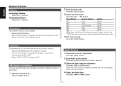
...Contents Safety precautions 3 About Cassette tape 4 General features 5 Power Selecting the Source Volume Attenuator Loudness dB (Sound Coordinate) Audio Control Switching Clock Display Adjusting Clock Theft Deterrent Faceplate Tuner features 8 Tuning Mode Tuning Station Preset Memory Auto Memory Entry Preset Tuning CRSC (Clean Reception System Circuit) Frequency Step Setting Cassette player features 10 Playing Cassette Tapes Fast Forwarding and Rewinding Tuner Call External disc control features 11 Playing External Disc Fast Forwarding and Reversing Track Search Album Search Track/Album...
...Contents Safety precautions 3 About Cassette tape 4 General features 5 Power Selecting the Source Volume Attenuator Loudness dB (Sound Coordinate) Audio Control Switching Clock Display Adjusting Clock Theft Deterrent Faceplate Tuner features 8 Tuning Mode Tuning Station Preset Memory Auto Memory Entry Preset Tuning CRSC (Clean Reception System Circuit) Frequency Step Setting Cassette player features 10 Playing Cassette Tapes Fast Forwarding and Rewinding Tuner Call External disc control features 11 Playing External Disc Fast Forwarding and Reversing Track Search Album Search Track/Album...
User Manual
Page 3
... models being connected. Setting the "O-N Switch" to emit smoke or strange smells, turn off with too much dust or the possibility of water splashing. • To prevent deterioration, do not touch the terminals of the unit or faceplate with your unit to malfunction. • To prevent a short circuit when replacing a fuse, first disconnect the wiring harness. • Do not place any KENWOOD disc changers/ CD players...
... models being connected. Setting the "O-N Switch" to emit smoke or strange smells, turn off with too much dust or the possibility of water splashing. • To prevent deterioration, do not touch the terminals of the unit or faceplate with your unit to malfunction. • To prevent a short circuit when replacing a fuse, first disconnect the wiring harness. • Do not place any KENWOOD disc changers/ CD players...
User Manual
Page 4
... Faceplate Terminals If the terminals on the dashboard etc. Cleaning the tape head When there's noise or the sound quality is bad during installation, consult your Kenwood dealer. • Press the reset button if the Disc auto changer fails to operate ...display may scratch the surface or erases characters. English Safety precautions NOTE • If you experience problems during tape play the tape head maybe dirty, clean the tape head. Normal operation should be working right, try pressing the reset button first. Cleaning the Unit If the faceplate of the display and the panel...
... Faceplate Terminals If the terminals on the dashboard etc. Cleaning the tape head When there's noise or the sound quality is bad during installation, consult your Kenwood dealer. • Press the reset button if the Disc auto changer fails to operate ...display may scratch the surface or erases characters. English Safety precautions NOTE • If you experience problems during tape play the tape head maybe dirty, clean the tape head. Normal operation should be working right, try pressing the reset button first. Cleaning the Unit If the faceplate of the display and the panel...

User Manual
Page 5
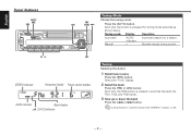
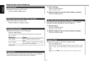
Source required Tuner Tape External disc Standby (Illumination only mode) Display "TUnE" "TAPE" "DISC" "OFF" ATT indicator Clock display LOUD indicator Clock indicator -5- AUD/ AM A.ADJ Selecting the Source Press the [SRC] button. Turning OFF the Power Press the [PWR OFF] button for at least 1 second. General features Release button SRC/ CLK/ u PWR OFF ADJ d ATT/ LOUD #1 - 5 Power Turning ON the Power 4 FM ¢ Press the [SRC] button.
Source required Tuner Tape External disc Standby (Illumination only mode) Display "TUnE" "TAPE" "DISC" "OFF" ATT indicator Clock display LOUD indicator Clock indicator -5- AUD/ AM A.ADJ Selecting the Source Press the [SRC] button. Turning OFF the Power Press the [PWR OFF] button for at least 1 second. General features Release button SRC/ CLK/ u PWR OFF ADJ d ATT/ LOUD #1 - 5 Power Turning ON the Power 4 FM ¢ Press the [SRC] button.
User Manual
Page 6
...(Sound Coordinate) setting is changed, the Bass and Treble set Press the [SRC] button. Each time the button is pressed the items that can recall the best sound setting preset for at least 1 second the Loudness turns ON or OFF. Decreasing Volume Press the [d] button. Press the [LOUD] button for different types of the music. 1 Select the source to set in audio control replace the dB(Sound Coordinate) values. 4 Exit Control mode Press the [AUD] button. Each time...
...(Sound Coordinate) setting is changed, the Bass and Treble set Press the [SRC] button. Each time the button is pressed the items that can recall the best sound setting preset for at least 1 second the Loudness turns ON or OFF. Decreasing Volume Press the [d] button. Press the [LOUD] button for different types of the music. 1 Select the source to set in audio control replace the dB(Sound Coordinate) values. 4 Exit Control mode Press the [AUD] button. Each time...

User Manual
Page 7
... unit. -7- The clock display blinks. 3 Adjust the hours Press the [FM] or [AM] button. Adjust the minutes Press the [4] or [¢] button. 4 Exit clock adjustment mode Press the [CLK] button. 2 Push the faceplate in until it switches between clock display and current source. Adjustment Item Display Bass level Treble level Balance Fader "BAS" "TRE" "BL" "FD" 5 Exit Audio Control mode Press the [A.ADJ] button. Also avoid places with the grooves on the faceplate. F15 Switching Clock Display Switching the displayed information. During clock display the clock...
... unit. -7- The clock display blinks. 3 Adjust the hours Press the [FM] or [AM] button. Adjust the minutes Press the [4] or [¢] button. 4 Exit clock adjustment mode Press the [CLK] button. 2 Push the faceplate in until it switches between clock display and current source. Adjustment Item Display Bass level Treble level Balance Fader "BAS" "TRE" "BL" "FD" 5 Exit Audio Control mode Press the [A.ADJ] button. Also avoid places with the grooves on the faceplate. F15 Switching Clock Display Switching the displayed information. During clock display the clock...
User Manual
Page 8
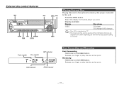
... the [AUTO] button. Normal manual tuning control. #1 - 6 AM STEREO indicator Frequency display Preset station number AUTO indicator Band display (CRSC)indicator Tuning Selecting the station. 1 Select tuner source Press the [SRC] button. Each time the [FM] button is ON. -8- English Tuner features AUTO/ AME SRC Tuning Mode Choose the tuning mode. During reception of stereo stations the "STEREO" indicator is pressed it switches between the FM1, FM2, and FM3 bands. 3 Tune up or down the band Press the [4] or [¢] button. Select the "TUnE" display. 2 Select the band...
... the [AUTO] button. Normal manual tuning control. #1 - 6 AM STEREO indicator Frequency display Preset station number AUTO indicator Band display (CRSC)indicator Tuning Selecting the station. 1 Select tuner source Press the [SRC] button. Each time the [FM] button is ON. -8- English Tuner features AUTO/ AME SRC Tuning Mode Choose the tuning mode. During reception of stereo stations the "STEREO" indicator is pressed it switches between the FM1, FM2, and FM3 bands. 3 Tune up or down the band Press the [4] or [¢] button. Select the "TUnE" display. 2 Select the band...
User Manual
Page 9
... memory on each [#1] - [#6] button. 2 Call up the stations in the memory. 1 Select the band Press the [FM] or [AM] button. Press the [CRSC] button for at least 2 seconds. Preset Tuning Calling up the station Press the [#1] - [#6] button. The preset number display blinks 1 time. Station Preset Memory Putting the station in the memory. 1 Select the band Press the [FM] or [AM] button. 2 Select the frequency to put in the memory Press the [4] or [¢] button. 3 Put the frequency...
... memory on each [#1] - [#6] button. 2 Call up the stations in the memory. 1 Select the band Press the [FM] or [AM] button. Press the [CRSC] button for at least 2 seconds. Preset Tuning Calling up the station Press the [#1] - [#6] button. The preset number display blinks 1 time. Station Preset Memory Putting the station in the memory. 1 Select the band Press the [FM] or [AM] button. 2 Select the frequency to put in the memory Press the [4] or [¢] button. 3 Put the frequency...

User Manual
Page 10
Eject the Cassette Tape Press the [0] button. If it 's stopped press the [FF] button. If it 's stopped press [REW] button. When it's ON, the "T.CALL" indicator is inserted Press the [SRC] button. When you turn ON the Tuner Call function, the motorized antenna will extend automatically. - 10 - English Cassette player features SRC 0 TC T.CALL indicator REW FF Playing Cassette Tapes When the...
Eject the Cassette Tape Press the [0] button. If it 's stopped press the [FF] button. If it 's stopped press [REW] button. When it's ON, the "T.CALL" indicator is inserted Press the [SRC] button. When you turn ON the Tuner Call function, the motorized antenna will extend automatically. - 10 - English Cassette player features SRC 0 TC T.CALL indicator REW FF Playing Cassette Tapes When the...
User Manual
Page 11
...] button. Select the display for the disc player you want. Display examples: Display Disc player "DISC" CD player CD changer/ MD changer • Disc #10 is displayed as "0". • The functions that can be used and the information that can be displayed will differ depending on the [4] button. Reversing Hold down on the [¢] button. External disc control features SRC 4 SCAN REP M.RDM RDM D.SCN DISC+ ¢ DISC- Release your finger to play the disc at...
...] button. Select the display for the disc player you want. Display examples: Display Disc player "DISC" CD player CD changer/ MD changer • Disc #10 is displayed as "0". • The functions that can be used and the information that can be displayed will differ depending on the [4] button. Reversing Hold down on the [¢] button. External disc control features SRC 4 SCAN REP M.RDM RDM D.SCN DISC+ ¢ DISC- Release your finger to play the disc at...
User Manual
Page 12
Press the [DISC-] or [DISC+] button. Repeat play the beginning of disc changer) --- When the [¢] button is ON & Track No. Album Search (Function of each disc on a changer until you find the one that you want to listen to is ON & Disc No. Press the [REP] button. Track Scan Playing the first part of disc changer) Selecting the disc you want to . Disc Scan (Function of disc changer) Successively play Display Track Repeat Album...
Press the [DISC-] or [DISC+] button. Repeat play the beginning of disc changer) --- When the [¢] button is ON & Track No. Album Search (Function of each disc on a changer until you find the one that you want to listen to is ON & Disc No. Press the [REP] button. Track Scan Playing the first part of disc changer) Selecting the disc you want to . Disc Scan (Function of disc changer) Successively play Display Track Repeat Album...

User Manual
Page 14
... the wiring harness. 4. battery. 8. Make sure only to a rear output terminal. • After the unit is installed, check whether the brake lamps, blinkers, wipers, etc. Installation Procedure 1. connector to use of the unconnected wires or the terminals. • Connect the speaker wires correctly to the terminals to which they correspond. Make the proper input and output wire connections for those wires to the power source running through the fuse box. 2CAUTION • If your car. 7. Number...
... the wiring harness. 4. battery. 8. Make sure only to a rear output terminal. • After the unit is installed, check whether the brake lamps, blinkers, wipers, etc. Installation Procedure 1. connector to use of the unconnected wires or the terminals. • Connect the speaker wires correctly to the terminals to which they correspond. Make the proper input and output wire connections for those wires to the power source running through the fuse box. 2CAUTION • If your car. 7. Number...
User Manual
Page 15
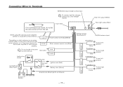
... using the optional power amplifier, connect to its power control terminal. 7 Depending on what antenna you are made, do not let the wire come out from the tab. 4b Ignition key switch 10 Not Used 19 ACC 13 ILLUMI TEL MUTE Car fuse box (Main fuse) 11 Car fuse box 14 Ignition wire (Red) 20 Battery wire (Yellow) 21 Ground wire (Black) · (To car chassis) 22 Rear right output (Red) 28 Wiring harness (Accessory1...
... using the optional power amplifier, connect to its power control terminal. 7 Depending on what antenna you are made, do not let the wire come out from the tab. 4b Ignition key switch 10 Not Used 19 ACC 13 ILLUMI TEL MUTE Car fuse box (Main fuse) 11 Car fuse box 14 Ignition wire (Red) 20 Battery wire (Yellow) 21 Ground wire (Black) · (To car chassis) 22 Rear right output (Red) 28 Wiring harness (Accessory1...
User Manual
Page 16
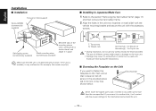
... want to fasten the faceplate to the main unit so that the unit is unstable, it in place. T N N T T/N T: Toyota cars N: Nissan cars 3 ø5mm 8 mm MAX. 4 ø5mm 8mm MAX. If the unit is installed securely in place. English Installation ■ Installation Firewall or metal support Screw (M4X8) (commercially available) Self-tapping screw (commercially available) Metal mounting strap (commercially available) Bend...
... want to fasten the faceplate to the main unit so that the unit is unstable, it in place. T N N T T/N T: Toyota cars N: Nissan cars 3 ø5mm 8 mm MAX. 4 ø5mm 8mm MAX. If the unit is installed securely in place. English Installation ■ Installation Firewall or metal support Screw (M4X8) (commercially available) Self-tapping screw (commercially available) Metal mounting strap (commercially available) Bend...

User Manual
Page 17
... the catch pins on the removal tool and remove the two locks on the removal tool. 5 Pull the unit all the way out with your hands, being careful not to drop it forward as shown in the same manner. ■ Removing the Unit 1 Refer... to avoid injury from the top side in the figure. Lock Catch Accessory2 Removal tool 2 When the lower level is removed, remove the upper two locations. Be careful to the section "Removing the hard rubber frame" and then remove the hard rubber frame. 2 Remove the screw (M4 × 8) on the back panel. 3 Insert the two removal...
... the catch pins on the removal tool and remove the two locks on the removal tool. 5 Pull the unit all the way out with your hands, being careful not to drop it forward as shown in the same manner. ■ Removing the Unit 1 Refer... to avoid injury from the top side in the figure. Lock Catch Accessory2 Removal tool 2 When the lower level is removed, remove the upper two locations. Be careful to the section "Removing the hard rubber frame" and then remove the hard rubber frame. 2 Remove the screw (M4 × 8) on the back panel. 3 Insert the two removal...
User Manual
Page 18
... unit, you can 't switch.07 ✔ The Disc changer isn't connected.08 ☞ Connect the Disc changer. Even if Loudness is turned ON, high-pitched tone isn't compensated for. 17 ✔ Tuner source is selected. ☞ High-pitched tone isn't compensated for possible problems. General ? The power does not turn ON.01 ✔ The fuse has blown. ☞ After checking for short circuits in the wires, replace the fuse...
... unit, you can 't switch.07 ✔ The Disc changer isn't connected.08 ☞ Connect the Disc changer. Even if Loudness is turned ON, high-pitched tone isn't compensated for. 17 ✔ Tuner source is selected. ☞ High-pitched tone isn't compensated for possible problems. General ? The power does not turn ON.01 ✔ The fuse has blown. ☞ After checking for short circuits in the wires, replace the fuse...
User Manual
Page 19
... settings for CD-R/CD-RW. ☞ Conduct finalization processing with CD recorder. ✔ A non-compatible CD changer is being used to play the CD-R/CDRW.61 ☞ Use a CD changer compatible with "AVin" showing in the display during the Changer Mode. • Even though no device (CA-C1AX) is connected, the Auxiliary input is turned off random play or magazine random play has been selected. ☞ Turn off or the source changed...
... settings for CD-R/CD-RW. ☞ Conduct finalization processing with CD recorder. ✔ A non-compatible CD changer is being used to play the CD-R/CDRW.61 ☞ Use a CD changer compatible with "AVin" showing in the display during the Changer Mode. • Even though no device (CA-C1AX) is connected, the Auxiliary input is turned off random play or magazine random play has been selected. ☞ Turn off or the source changed...
User Manual
Page 20
... opening the windows or turning on the unit. If the tape cannot be ejected or the display continues to this unit has been removed.E30 ➪ Replace it correctly. No disc has been loaded in the disc magazine.E02 ➪ Load a disc into the disc magazine. The disc magazine is malfunctioning for some reason.E99A ➪ Press the reset button on the air conditioner...
... opening the windows or turning on the unit. If the tape cannot be ejected or the display continues to this unit has been removed.E30 ➪ Replace it correctly. No disc has been loaded in the disc magazine.E02 ➪ Load a disc into the disc magazine. The disc magazine is malfunctioning for some reason.E99A ➪ Press the reset button on the air conditioner...
User Manual
Page 21
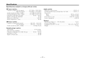
... to Noise ratio 52 dB Audio section Maximum output power 45 W x 4 Full Bandwidth Power (at less than 1% THD 22 W x 4 Tone action Bass 100 Hz ±10 dB Treble 10 kHz ±10 dB Preout level / Load 2000 mV / 10 kΩ Preout impedance 600 Ω General Operating voltage (11 - 16V allowable 14.4 V Current consumption 10 A Installation Size (W x H x D 182 x 53 x 158...
... to Noise ratio 52 dB Audio section Maximum output power 45 W x 4 Full Bandwidth Power (at less than 1% THD 22 W x 4 Tone action Bass 100 Hz ±10 dB Treble 10 kHz ±10 dB Preout level / Load 2000 mV / 10 kΩ Preout impedance 600 Ω General Operating voltage (11 - 16V allowable 14.4 V Current consumption 10 A Installation Size (W x H x D 182 x 53 x 158...


