

User Manual
Page 2
... power Units are coloured in accordance with a small screwdriver or other countries AC voltage selection This unit operates on the rear panel is set to your home or the cable is no danger of hazardous radiation outside the product. and Canada AC 120V only Australia AC 240 V only DVR-505/DVR-7000 (EN) Caution : Read this page carefully to the mains supply...
... power Units are coloured in accordance with a small screwdriver or other countries AC voltage selection This unit operates on the rear panel is set to your home or the cable is no danger of hazardous radiation outside the product. and Canada AC 120V only Australia AC 240 V only DVR-505/DVR-7000 (EN) Caution : Read this page carefully to the mains supply...

User Manual
Page 3
... DVD discs 9 Region codes 10 Region codes in the world 10 Examples of TV screen display of each video format ...... 10 Video formats 11 Video formats of difficulty 62 Specifications 65 Contents Caution : Read the pages marked 3 DVR-505/DVR-7000 (EN) carefully to Audio video equipments 15 Connecting a Camcorder or Video game machine 15 Controls and indicators 16 Operation of a P.B.C.-compatible VCD) (To P.B.C. VCD playback 36 Playback without using the menu...
... DVD discs 9 Region codes 10 Region codes in the world 10 Examples of TV screen display of each video format ...... 10 Video formats 11 Video formats of difficulty 62 Specifications 65 Contents Caution : Read the pages marked 3 DVR-505/DVR-7000 (EN) carefully to Audio video equipments 15 Connecting a Camcorder or Video game machine 15 Controls and indicators 16 Operation of a P.B.C.-compatible VCD) (To P.B.C. VCD playback 36 Playback without using the menu...

User Manual
Page 4
... main unit FM indoor antenna (1) Loop antenna (1) Video cord (1) Preparations Remote control unit (1) Batteries (LR03/AAA) (2) SCART plug (1) (for instance when you transport or ship the unit in the area where the system is to which the system is necessary.) Speaker model names System Front speakers and surround speakers Subwoofer DVR-505 KS-305DV (Left speaker, right speaker, SW-15DV center speaker and surround speakers) DVR-7000 KSW-7000 (Left speaker, right speaker, center speaker, surround speakers and subwoofer) CHANNEL SPACE setting (Except for the U.S.A., Canada...
... main unit FM indoor antenna (1) Loop antenna (1) Video cord (1) Preparations Remote control unit (1) Batteries (LR03/AAA) (2) SCART plug (1) (for instance when you transport or ship the unit in the area where the system is to which the system is necessary.) Speaker model names System Front speakers and surround speakers Subwoofer DVR-505 KS-305DV (Left speaker, right speaker, SW-15DV center speaker and surround speakers) DVR-7000 KSW-7000 (Left speaker, right speaker, center speaker, surround speakers and subwoofer) CHANNEL SPACE setting (Except for the U.S.A., Canada...

User Manual
Page 5
... a wet basement, or near water - Power sources - Power-cord protection - The appliance should not be situated away from sources of magnetic fields such as alcohol, paint thinner, gasoline, or benzine, etc. Slots and openings in the instruction manual. Place the appliance at extremely low, or freezing temperatures. Never remove the enclosure. to insert the plug fully into contact with a polarized...
... a wet basement, or near water - Power sources - Power-cord protection - The appliance should not be situated away from sources of magnetic fields such as alcohol, paint thinner, gasoline, or benzine, etc. Slots and openings in the instruction manual. Place the appliance at extremely low, or freezing temperatures. Never remove the enclosure. to insert the plug fully into contact with a polarized...

User Manual
Page 6
... the rear panel. NATIONAL ELECTRICAL CODE ANTENNA LEAD IN WIRE ANTENNA DISCHARGE UNIT (NEC SECTION 810-20) GROUNDING CONDUCTORS (NEC SECTION 810-21) GROUND CLAMP POWER SERVICE GROUNDING ELECTRODE SYSTEM (NEC ART 250, PART H) 20. For added protection for long periods of the lead-in fire, electric shock, or other controls may result in the instruction manual. Do not connect other audio equipment with a power consumption...
... the rear panel. NATIONAL ELECTRICAL CODE ANTENNA LEAD IN WIRE ANTENNA DISCHARGE UNIT (NEC SECTION 810-20) GROUNDING CONDUCTORS (NEC SECTION 810-21) GROUND CLAMP POWER SERVICE GROUNDING ELECTRODE SYSTEM (NEC ART 250, PART H) 20. For added protection for long periods of the lead-in fire, electric shock, or other controls may result in the instruction manual. Do not connect other audio equipment with a power consumption...

User Manual
Page 7
... inside the unit when there is installed increases, etc. In this unit, carry out the following operations. 1 Remove the disc from power outlet. ANYONE WISHING TO COPY COMMERCIALLY AVAILABLE TAPES OR DISC SHOULD CONTACT THE MECHANICAL COPYRIGHT PROTECTION SOCIETY LIMITED OR THE PERFORMING RIGHTS SOCIETY LIMITED. BOOST Tuner section Receiving band Frequency Preset stations Tuning mode setting DVD section Menu setup Power status WARNING NOTICE: IN MOST CASES...
... inside the unit when there is installed increases, etc. In this unit, carry out the following operations. 1 Remove the disc from power outlet. ANYONE WISHING TO COPY COMMERCIALLY AVAILABLE TAPES OR DISC SHOULD CONTACT THE MECHANICAL COPYRIGHT PROTECTION SOCIETY LIMITED OR THE PERFORMING RIGHTS SOCIETY LIMITED. BOOST Tuner section Receiving band Frequency Preset stations Tuning mode setting DVD section Menu setup Power status WARNING NOTICE: IN MOST CASES...

User Manual
Page 8
... cleaners Do not use a cracked or deformed disc or a disc repaired with the instructions. Reorient or relocate the receiving antenna. - - DVR-505/DVR-7000 (EN) In regard to correct the interference by turning the equipment off and on a circuit different from the player and store it from that to be used in the player. Location: Laser Pick-up Unit Cover inside the product relating to...
... cleaners Do not use a cracked or deformed disc or a disc repaired with the instructions. Reorient or relocate the receiving antenna. - - DVR-505/DVR-7000 (EN) In regard to correct the interference by turning the equipment off and on a circuit different from the player and store it from that to be used in the player. Location: Laser Pick-up Unit Cover inside the product relating to...

User Manual
Page 10
... Try play the DVD discs carrying the region codes matching the region code of the player. When the player is used . 10 Region codes DVR-505/DVR-7000 (EN) Every player of this model has a certain region code assigned to it based on the right, stop playback and switch the screen display formats of this unit and the TV to another format. When your TV is compatible only with...
... Try play the DVD discs carrying the region codes matching the region code of the player. When the player is used . 10 Region codes DVR-505/DVR-7000 (EN) Every player of this model has a certain region code assigned to it based on the right, stop playback and switch the screen display formats of this unit and the TV to another format. When your TV is compatible only with...

User Manual
Page 11
... 4 Russia 5 China 6 Preparations Set the video formats of the DVD discs to be reproduced when a disc recorded with the playable video format by referring to the following table. ÷ See the region code table on the TV screen connected to the player, it is displayed on this unit as described below. 1 Check the video format(s) used by you. As this player plays discs according to their...
... 4 Russia 5 China 6 Preparations Set the video formats of the DVD discs to be reproduced when a disc recorded with the playable video format by referring to the following table. ÷ See the region code table on the TV screen connected to the player, it is displayed on this unit as described below. 1 Check the video format(s) used by you. As this player plays discs according to their...

User Manual
Page 12
... the same color at the speaker terminal panel on the main unit Red Green Blue Orange Brown Gray Surround speaker L Subwoofer Speakers for DVR-505. Caution: DVR-505/DVR-7000 (EN) Do not plug in the power lead until all connec- Connect matching the color of the speaker terminal (+ side) and the color of microcomputer If operation is not possible or erroneous display appears even though all...
... the same color at the speaker terminal panel on the main unit Red Green Blue Orange Brown Gray Surround speaker L Subwoofer Speakers for DVR-505. Caution: DVR-505/DVR-7000 (EN) Do not plug in the power lead until all connec- Connect matching the color of the speaker terminal (+ side) and the color of microcomputer If operation is not possible or erroneous display appears even though all...

User Manual
Page 14
.... Satellite tuner Remove protective cap before connecting. 14 System Connections DVR-505/DVR-7000 (EN) Connecting to a TV Depending on the digital output of the satellite tuner. S-VIDEO terminal : S-video signal connected to the SCART terminal of COMPONENT connection. VIDEO terminal : Composite video signal connected to the (VIDEO) VCR IN, the (VIDEO) SAT TV IN, or the AV AUX VIDEO terminal. Connect the S-video or the COMPOSITE video cable also in case of the TV and connect the COMPOSITE video cord.
.... Satellite tuner Remove protective cap before connecting. 14 System Connections DVR-505/DVR-7000 (EN) Connecting to a TV Depending on the digital output of the satellite tuner. S-VIDEO terminal : S-video signal connected to the SCART terminal of COMPONENT connection. VIDEO terminal : Composite video signal connected to the (VIDEO) VCR IN, the (VIDEO) SAT TV IN, or the AV AUX VIDEO terminal. Connect the S-video or the COMPOSITE video cable also in case of the TV and connect the COMPOSITE video cord.

User Manual
Page 16
... operation status when the POWER switch is set to ON again. When the POWER switch is set to OFF in operation status, the unit will return to STANDBY status when the POWER switch is set to ON again. AV AUX VIDEO jack @ AV AUX AUDIO jacks # AV AUX OPTICAL input jack $ PHONES jack % Door ^ 6 (PLAY/PAUSE) key & 7 (STOP) key * INPUT key ( VOLUME CONTROL knob ) 0 (EJECT) key ¡ Disc tray DIGITAL (OPTICAL) % @# $ STANDBY indicator The STANDBY indicator lights when the power cable is plugged into an outlet and the POWER switch...
... operation status when the POWER switch is set to ON again. When the POWER switch is set to OFF in operation status, the unit will return to STANDBY status when the POWER switch is set to ON again. AV AUX VIDEO jack @ AV AUX AUDIO jacks # AV AUX OPTICAL input jack $ PHONES jack % Door ^ 6 (PLAY/PAUSE) key & 7 (STOP) key * INPUT key ( VOLUME CONTROL knob ) 0 (EJECT) key ¡ Disc tray DIGITAL (OPTICAL) % @# $ STANDBY indicator The STANDBY indicator lights when the power cable is plugged into an outlet and the POWER switch...
User Manual
Page 17
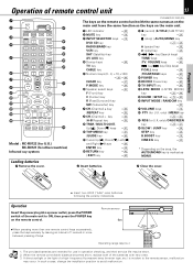
... MENU key ‡ /GUIDE key P ! Remote sensor 6m ÷ When pressing more than one remote control keys successively, press the keys securely by leaving an interval of 1 second or more between pressing of remote control unit 17 1 2 3 4 5 6 7 8 9 0 ! @ # $ MUTE POWER DVD CD AV AUX INPUT SELECTOR RADIO VCR SAT BAND DEVICE TV CABLE TV INPUT 1 2 3 LSTN MODE 4 5 6 SOUND 7 8 9 SETUP +10 +100 INPUT MODE CLEAR 0 P.MODE RANDOM F C R SW + REPEAT CH. In such a case, change the installation...
... MENU key ‡ /GUIDE key P ! Remote sensor 6m ÷ When pressing more than one remote control keys successively, press the keys securely by leaving an interval of 1 second or more between pressing of remote control unit 17 1 2 3 4 5 6 7 8 9 0 ! @ # $ MUTE POWER DVD CD AV AUX INPUT SELECTOR RADIO VCR SAT BAND DEVICE TV CABLE TV INPUT 1 2 3 LSTN MODE 4 5 6 SOUND 7 8 9 SETUP +10 +100 INPUT MODE CLEAR 0 P.MODE RANDOM F C R SW + REPEAT CH. In such a case, change the installation...

User Manual
Page 18
... the speaker setting value or when CINE.EQ has been set in the disc tray and the DVD CD key is pressed, disc playback will not be operated. The present mode of operation with SAT and AV Note AUX. 18 Let's put out some sound Preparation ÷ set to the maximum value. MUTE key INPUT SELECTOR keys DVR-505/DVR-7000 (EN) POWER key VOLUME keys POWER switch VOLUME CONTROL knob INPUT key PHONES jack Basic use method...
... the speaker setting value or when CINE.EQ has been set in the disc tray and the DVD CD key is pressed, disc playback will not be operated. The present mode of operation with SAT and AV Note AUX. 18 Let's put out some sound Preparation ÷ set to the maximum value. MUTE key INPUT SELECTOR keys DVR-505/DVR-7000 (EN) POWER key VOLUME keys POWER switch VOLUME CONTROL knob INPUT key PHONES jack Basic use method...

User Manual
Page 19
... preset equalizers, so that various sounds can be adjusted only STEREO mode) LSTN MODE 2Press the SOUND key SOUND SETUP 3Select treble level To increase TRIM ULTI C ON To decrease T. Changing the Tone Let's put out some sound 19 DVR-505/DVR-7000 (EN) This unit is equipped with DOLBY DIGITAL and DTS source. REMOTE Press the B.BOOST key Each press switches the B.BOOST on , richer bass tones can be adjusted...
... preset equalizers, so that various sounds can be adjusted only STEREO mode) LSTN MODE 2Press the SOUND key SOUND SETUP 3Select treble level To increase TRIM ULTI C ON To decrease T. Changing the Tone Let's put out some sound 19 DVR-505/DVR-7000 (EN) This unit is equipped with DOLBY DIGITAL and DTS source. REMOTE Press the B.BOOST key Each press switches the B.BOOST on , richer bass tones can be adjusted...

User Manual
Page 25
... of disc DVD CD key 8(Pause) key 3(Play) key 25 DVR-505/DVR-7000 (EN) PLAY/PAUSE key STOP key INPUT key Operations Basic play will start from the point where the playback had been stopped. Then press ENTER to select specific menu you want to pause the disc. This is recorded on the screen. TOP MENU GUIDE ÷ When the PLAY/PAUSE key on the remote control unit to play by...
... of disc DVD CD key 8(Pause) key 3(Play) key 25 DVR-505/DVR-7000 (EN) PLAY/PAUSE key STOP key INPUT key Operations Basic play will start from the point where the playback had been stopped. Then press ENTER to select specific menu you want to pause the disc. This is recorded on the screen. TOP MENU GUIDE ÷ When the PLAY/PAUSE key on the remote control unit to play by...

User Manual
Page 48
... front-channel stereo to the surround speakers to your surroundings. (To change the Center Width, press SOUND key 3 times at the movies. 48 Setting up LISTEN mode DVR-505/DVR-7000 (EN) What are full-frequency and independent, so sound can completely envelop you . This listen mode is divided into 5-channel signals composed of Dolby Pro Logic II Music mode. The adjustment for other type of audio delivery can experience true home-theater sound with...
... front-channel stereo to the surround speakers to your surroundings. (To change the Center Width, press SOUND key 3 times at the movies. 48 Setting up LISTEN mode DVR-505/DVR-7000 (EN) What are full-frequency and independent, so sound can completely envelop you . This listen mode is divided into 5-channel signals composed of Dolby Pro Logic II Music mode. The adjustment for other type of audio delivery can experience true home-theater sound with...
User Manual
Page 49
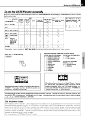
... the audio system, proper precautions should be connected to the digital output (S/P DIF, AES/EBU, or TosLink) of the CD, LD or DVD player. Press the LSTN MODE key. "DTS" and "DTS Digital Surround" are trademarks of Dolby Laboratories. This unit is equipped with the SOUND RETRIEVAL SYSTEM. Setting up LISTEN mode 49 DVR-505/DVR-7000 (EN) To set the LISTEN mode manually According to the contents of the disc played in this product...
... the audio system, proper precautions should be connected to the digital output (S/P DIF, AES/EBU, or TosLink) of the CD, LD or DVD player. Press the LSTN MODE key. "DTS" and "DTS Digital Surround" are trademarks of Dolby Laboratories. This unit is equipped with the SOUND RETRIEVAL SYSTEM. Setting up LISTEN mode 49 DVR-505/DVR-7000 (EN) To set the LISTEN mode manually According to the contents of the disc played in this product...
User Manual
Page 62
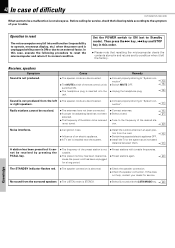
... Standby mode). If this does not help, contact your trouble. nection". @ ÷ Switch MUTE OFF. * ÷ Unplug the headphone plug. * Sound is STEREO. ÷ Select Surround with tunable frequencies. ÷ Preset stations again. ™ The STANDBY indicator flashes red. ÷ The speaker connection is installed near the system. ÷ Install the outdoor antenna in an apart posi- tion from the surround speakers ÷ The LISTEN mode is not produced from the left the factory...
... Standby mode). If this does not help, contact your trouble. nection". @ ÷ Switch MUTE OFF. * ÷ Unplug the headphone plug. * Sound is STEREO. ÷ Select Surround with tunable frequencies. ÷ Preset stations again. ™ The STANDBY indicator flashes red. ÷ The speaker connection is installed near the system. ÷ Install the outdoor antenna in an apart posi- tion from the surround speakers ÷ The LISTEN mode is not produced from the left the factory...

User Manual
Page 63
..." section ,and use a disc with the appropriate video format for the input or device to be operated. * DVD / CD player unit Symptom Cause Remedy Playback does not start playing, although the time differs depending on . ÷ The connection cords are required for the disc. age is not possible. forward and fast reverse operations. The top and bottom of the screen cannot be displayed when the DVD disc being played does not...
..." section ,and use a disc with the appropriate video format for the input or device to be operated. * DVD / CD player unit Symptom Cause Remedy Playback does not start playing, although the time differs depending on . ÷ The connection cords are required for the disc. age is not possible. forward and fast reverse operations. The top and bottom of the screen cannot be displayed when the DVD disc being played does not...


