
Instructions
Page 2
...receptacle or other outlet unless the blades can be sure to prevent blade exposure. Changes or modifications not approved by JVC could void the warranty. * When you don't use this TV set for a long period of mercury. Do not allow objects or liquid into the cabinet openings. 5. It...unplug the unit and call a service technician. For disposal or recycling information, please contact your community due to repair it yourself or remove the rear cover. Do not remove cover (or back). Operate only from the AC outlet and antenna for USA) This product has a High Intensity Discharge...
...receptacle or other outlet unless the blades can be sure to prevent blade exposure. Changes or modifications not approved by JVC could void the warranty. * When you don't use this TV set for a long period of mercury. Do not allow objects or liquid into the cabinet openings. 5. It...unplug the unit and call a service technician. For disposal or recycling information, please contact your community due to repair it yourself or remove the rear cover. Do not remove cover (or back). Operate only from the AC outlet and antenna for USA) This product has a High Intensity Discharge...

Instructions
Page 4
... not be exposed to dripping or splashing and no guarantee that to correct the interference by one or more of furniture. Install the TV in a particular installation. If this equipment does cause harmful interference to qualified service personnel. 13) Unplug this apparatus during operation. INPUT... between the equipment and receiver. - Keep to provide reasonable protection against harmful interference in a residential installation. Do not tilt the TV towards the left or right, or towards the back. - These limits are designed to the minimum distance guidelines shown for safe ...
... not be exposed to dripping or splashing and no guarantee that to correct the interference by one or more of furniture. Install the TV in a particular installation. If this equipment does cause harmful interference to qualified service personnel. 13) Unplug this apparatus during operation. INPUT... between the equipment and receiver. - Keep to provide reasonable protection against harmful interference in a residential installation. Do not tilt the TV towards the left or right, or towards the back. - These limits are designed to the minimum distance guidelines shown for safe ...
Instructions
Page 5
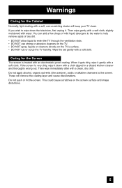
...like acetone), acidic or alkaline cleansers to wipe down with a cloth dipped in a diluted kitchen cleaner and thoroughly wrung-out. These will keep your TV clean. Then wipe gently with a soft cloth, slightly moistened with a clean, dry cloth. Then wipe immediately after with water. This could cause ...scratches on the TV's surface. • DO NOT rub or scrub the TV harshly. You can add a few drops of mild liquid detergent to the water to help remove spots of oily dirt. ...
...like acetone), acidic or alkaline cleansers to wipe down with a cloth dipped in a diluted kitchen cleaner and thoroughly wrung-out. These will keep your TV clean. Then wipe gently with a soft cloth, slightly moistened with a clean, dry cloth. Then wipe immediately after with water. This could cause ...scratches on the TV's surface. • DO NOT rub or scrub the TV harshly. You can add a few drops of mild liquid detergent to the water to help remove spots of oily dirt. ...

Instructions
Page 6
...then goes out. There are 2 LED indicators on the front panel of the device and important information which the TV is turned off, the picture on how to recycle the lamp, refer to it . When the POWER button... becomes dark. Cooling the inside of malfunctions. When the cooling is being performed. Cautions related to project the picture onto the screen. Once the screen is dark, cooling is in orange at their full...blinks in the Appendix. Warnings Thank you for purchasing JVC's model HD-70G886, HD-61Z886 or HD-61Z786 HDTV-ready projection television which are summarized below .
...then goes out. There are 2 LED indicators on the front panel of the device and important information which the TV is turned off, the picture on how to recycle the lamp, refer to it . When the POWER button... becomes dark. Cooling the inside of malfunctions. When the cooling is being performed. Cautions related to project the picture onto the screen. Once the screen is dark, cooling is in orange at their full...blinks in the Appendix. Warnings Thank you for purchasing JVC's model HD-70G886, HD-61Z886 or HD-61Z786 HDTV-ready projection television which are summarized below .
Instructions
Page 7
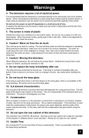
...television to clean the screen. 6. Caution! Be careful not to wallpaper. Opening up the rear cabinet will violate the copyright of the lamp being shortened. 5. It subjects the television and... breaking. Do not replace the lamp immediately after use . ILA element characteristics Do not project still pictures or pictures that have still segments for details on how to fall. 8. Usable...Also, take care to the warm air from the warm air ducts. Long exposure to keep the TV on the lamp glass, there is a possibility of the life of the wallpaper to another device,...
...television to clean the screen. 6. Caution! Be careful not to wallpaper. Opening up the rear cabinet will violate the copyright of the lamp being shortened. 5. It subjects the television and... breaking. Do not replace the lamp immediately after use . ILA element characteristics Do not project still pictures or pictures that have still segments for details on how to fall. 8. Usable...Also, take care to the warm air from the warm air ducts. Long exposure to keep the TV on the lamp glass, there is a possibility of the life of the wallpaper to another device,...

Instructions
Page 8
... Muting 53 Front Panel Lock 54 V1 Smart Input 54 Video Input Label 55 Position Adjustment 56 Power Indicator 56 Video-1 Monitor Out 57 TV Speaker 57 Audio Out 57 Digital-In 58 Digital-In Audio 58 Center CH Input 58 Picture Adjust 59 Picture Settings 59 Adjust Picture Settings... 59 Color Temperature 59 Digital Noise Clear 60 Color Management 60 Dynamic Gamma 60 Smart Picture 61 Reset 61 8 Sound Adjust 62 Sound Settings 62 Adjust Sound Settings 62 Reset 62 Clock/Timers 63 Set Clock 63 On/Off Timer 64 Lamp ...
... Muting 53 Front Panel Lock 54 V1 Smart Input 54 Video Input Label 55 Position Adjustment 56 Power Indicator 56 Video-1 Monitor Out 57 TV Speaker 57 Audio Out 57 Digital-In 58 Digital-In Audio 58 Center CH Input 58 Picture Adjust 59 Picture Settings 59 Adjust Picture Settings... 59 Color Temperature 59 Digital Noise Clear 60 Color Management 60 Dynamic Gamma 60 Smart Picture 61 Reset 61 8 Sound Adjust 62 Sound Settings 62 Adjust Sound Settings 62 Reset 62 Clock/Timers 63 Set Clock 63 On/Off Timer 64 Lamp ...

Instructions
Page 10
... PRO 0 VIDEO STATUS C.C. Two Way Splitter x 1 2-WAY SPLITTER RF Cables x 2 10 Quick Setup Unpacking your TV Thank you have all of a JVC Color Television. NATURAL SOUND CINEMA 9 RETURN+ TV SUB CHANNEL SUB LIGHT MUTING CH GUIDE VOL OK VOL Note: Your television CH MENU VCR CHANNEL PREV NEXT BACK... VCR DVD POWER TV VCR REW PLAY FF and/or remote control may differ REC STOP PAUSE...
... PRO 0 VIDEO STATUS C.C. Two Way Splitter x 1 2-WAY SPLITTER RF Cables x 2 10 Quick Setup Unpacking your TV Thank you have all of a JVC Color Television. NATURAL SOUND CINEMA 9 RETURN+ TV SUB CHANNEL SUB LIGHT MUTING CH GUIDE VOL OK VOL Note: Your television CH MENU VCR CHANNEL PREV NEXT BACK... VCR DVD POWER TV VCR REW PLAY FF and/or remote control may differ REC STOP PAUSE...
Instructions
Page 11
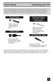
... connect JVC AV CompuLink capable components for an automated home theater. Used to make these connections you will use with S-Video VCRs, Camcorders and DVD players. Coaxial Cables Used to connect an external antenna or cable TV system to your television. To make video connections with your TV. Quick Setup Unpacking your TV Once...
... connect JVC AV CompuLink capable components for an automated home theater. Used to make these connections you will use with S-Video VCRs, Camcorders and DVD players. Coaxial Cables Used to connect an external antenna or cable TV system to your television. To make video connections with your TV. Quick Setup Unpacking your TV Once...

Instructions
Page 12
These will help assist you connect your television to another device, as well as use the remote to set up your specific TV and remote. SERVICE ONLY ATSC /DIGITAL CABLE IN I DIGITAL IN AV COMPULINK III VIDEO (DIGITAL) _ AUDIO (DIGITAL) CABLE CARD CENTER CHANNEL INPUT INPUT-2 Y...PC IN (D-SUB) L AUDIO OUTPUT 75Ω (VHF/UHF) R R MONITOR /REC OUT LICENSED UNDER THE FOLLOWING U.S. PATENTS 6,183,091 6,419,362 12 Rear Panel Diagram MODELS: HD-70G886 HD-61Z886 HD-61Z786 Note: The terminal labeled "SERVICE ONLY", is exclusively used to update the software version. Quick Setup...
These will help assist you connect your television to another device, as well as use the remote to set up your specific TV and remote. SERVICE ONLY ATSC /DIGITAL CABLE IN I DIGITAL IN AV COMPULINK III VIDEO (DIGITAL) _ AUDIO (DIGITAL) CABLE CARD CENTER CHANNEL INPUT INPUT-2 Y...PC IN (D-SUB) L AUDIO OUTPUT 75Ω (VHF/UHF) R R MONITOR /REC OUT LICENSED UNDER THE FOLLOWING U.S. PATENTS 6,183,091 6,419,362 12 Rear Panel Diagram MODELS: HD-70G886 HD-61Z886 HD-61Z786 Note: The terminal labeled "SERVICE ONLY", is exclusively used to update the software version. Quick Setup...

Instructions
Page 13
To open the door, gently press the arrow. MODELS: HD-70G886, HD-61Z886, HD-61Z786 Side Panel Diagram INPUT MENU INPUT 4 S-VIDEO OPERATE + CHANNEL - OVER VIDEO + VOLUME - L/MONO R AUDIO MODELS: HD-70G886, HD-61Z886, HD-61Z786 13 Quick Setup Front Panel Diagram TV Models LAMP/PROGRAM POWER LAMP/PROGRAM POWER LAMP/PROGRAM LED POWER LED MEDIA CARD SLOT Close door when using media cards SD/ MMC MEMORY xD-Picture STICK Card COMPACT FLASH • For information on the LED, see page 99. • Media Card Slot is for HD-70G886 ONLY.
To open the door, gently press the arrow. MODELS: HD-70G886, HD-61Z886, HD-61Z786 Side Panel Diagram INPUT MENU INPUT 4 S-VIDEO OPERATE + CHANNEL - OVER VIDEO + VOLUME - L/MONO R AUDIO MODELS: HD-70G886, HD-61Z886, HD-61Z786 13 Quick Setup Front Panel Diagram TV Models LAMP/PROGRAM POWER LAMP/PROGRAM POWER LAMP/PROGRAM LED POWER LED MEDIA CARD SLOT Close door when using media cards SD/ MMC MEMORY xD-Picture STICK Card COMPACT FLASH • For information on the LED, see page 99. • Media Card Slot is for HD-70G886 ONLY.

Instructions
Page 14
... CHANNEL SUB LIGHT MUTING CH GUIDE VOL OK VOL CH MENU VCR CHANNEL PREV NEXT BACK VCR DVD POWER TV VCR REW PLAY FF REC STOP PAUSE OPEN CLOSE STILL PAUSE RM-C14G RM-C14G MODELS: HD-70G886 HD-61Z886 HD-61Z786 • For information ... buttons, see pages 66 - 76 and 80 - 85. • i.LINK MENU, TIMER, SUB CHANNEL, FAVORITE and GUIDE buttons are for digital channels. Quick Setup TV Remote Control TV CATV VCR DVD POWER ASPECT MULTI SCREEN TWIN INDEX SELECT SLEEP FREEZE SWAP ML/MTS DISPLAY + INPUT 123 D/A 4 5 6 i.LINK MENU 78 TIMER TUNE THEATER...
... CHANNEL SUB LIGHT MUTING CH GUIDE VOL OK VOL CH MENU VCR CHANNEL PREV NEXT BACK VCR DVD POWER TV VCR REW PLAY FF REC STOP PAUSE OPEN CLOSE STILL PAUSE RM-C14G RM-C14G MODELS: HD-70G886 HD-61Z886 HD-61Z786 • For information ... buttons, see pages 66 - 76 and 80 - 85. • i.LINK MENU, TIMER, SUB CHANNEL, FAVORITE and GUIDE buttons are for digital channels. Quick Setup TV Remote Control TV CATV VCR DVD POWER ASPECT MULTI SCREEN TWIN INDEX SELECT SLEEP FREEZE SWAP ML/MTS DISPLAY + INPUT 123 D/A 4 5 6 i.LINK MENU 78 TIMER TUNE THEATER...
Instructions
Page 15
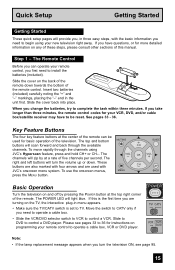
... right corner of the remote. The top and bottom MUTING GUIDE buttons will light blue. Move the switch to begin using JVC's Hyperscan feature, press and hold CH+ or CH-. POWER T TV CATV MUL VCR DVD Note: • If the lamp replacement message appears when you first need to CATV only if... 33 - 36. Basic Operation Turn the television on any of these steps, please consult other sections of this is set to be used with CH JVC's onscreen menu system. Quick Setup Getting Started Getting Started These quick setup pages will zip by pressing the POWER button at the center of the...
... right corner of the remote. The top and bottom MUTING GUIDE buttons will light blue. Move the switch to begin using JVC's Hyperscan feature, press and hold CH+ or CH-. POWER T TV CATV MUL VCR DVD Note: • If the lamp replacement message appears when you first need to CATV only if... 33 - 36. Basic Operation Turn the television on any of these steps, please consult other sections of this is set to be used with CH JVC's onscreen menu system. Quick Setup Getting Started Getting Started These quick setup pages will zip by pressing the POWER button at the center of the...
Instructions
Page 16
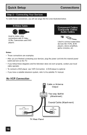
... and the television does not work properly, contact your devices, plug the power cord into the nearest power outlet and turn on the TV. • If you follow these connections, you have a satellite television system, refer to connect audio/video devices like the ones illustrated...DIGITAL CABLE IN I IN Two-way Splitter OUT OUT (Attachment) Coaxial Cable (Attachment) 75Ω (VHF/UHF) TV Rear Panel 16 Quick Setup Connections Step 2 - Used to the satellite TV manual. A DVD player is optional • If you will use plugs like VCRs, DVD players, stereo amplifiers,...
... and the television does not work properly, contact your devices, plug the power cord into the nearest power outlet and turn on the TV. • If you follow these connections, you have a satellite television system, refer to connect audio/video devices like the ones illustrated...DIGITAL CABLE IN I IN Two-way Splitter OUT OUT (Attachment) Coaxial Cable (Attachment) 75Ω (VHF/UHF) TV Rear Panel 16 Quick Setup Connections Step 2 - Used to the satellite TV manual. A DVD player is optional • If you will use plugs like VCRs, DVD players, stereo amplifiers,...

Instructions
Page 17
... OUT R L V IN OUT Two-Way Splitter IN (Attachment) OUT OUT Coaxial Cable (Attachment) ATSC /DIGITAL CABLE IN I 75Ω (VHF/UHF) TV Rear Panel S-VIDEO S-VIDEO OR OVER VIDEO L I AUDIO I R INPUT-3 TV Rear Panel OVER Y VIDEO L Pb I AUDIO I R Pr INPUT-1 AUDIO OUT L R Y PB PR OUT Green Blue Red DVD Player (OPTIONAL) Note: • If...
... OUT R L V IN OUT Two-Way Splitter IN (Attachment) OUT OUT Coaxial Cable (Attachment) ATSC /DIGITAL CABLE IN I 75Ω (VHF/UHF) TV Rear Panel S-VIDEO S-VIDEO OR OVER VIDEO L I AUDIO I R INPUT-3 TV Rear Panel OVER Y VIDEO L Pb I AUDIO I R Pr INPUT-1 AUDIO OUT L R Y PB PR OUT Green Blue Red DVD Player (OPTIONAL) Note: • If...

Instructions
Page 18
Quick Setup Diagram #2 Cable or Antenna Output Connections Two-Way Splitter IN OUT OUT VCR IN OUT Two-Way Splitter IN (Attachment) OUT OUT Coaxial Cable (Attachment) ATSC /DIGITAL CABLE IN I 75Ω (VHF/UHF) TV Rear Panel S-VIDEO R L V IN OUT S-VIDEO OR OVER VIDEO L I AUDIO I R INPUT-3 TV Rear Panel TV Rear Panel OVER Y VIDEO L Pb I AUDIO I R Pr INPUT-1 AUDIO OUT L R Y PB PR OUT Green Blue Red DVD Player (OPTIONAL) 18
Quick Setup Diagram #2 Cable or Antenna Output Connections Two-Way Splitter IN OUT OUT VCR IN OUT Two-Way Splitter IN (Attachment) OUT OUT Coaxial Cable (Attachment) ATSC /DIGITAL CABLE IN I 75Ω (VHF/UHF) TV Rear Panel S-VIDEO R L V IN OUT S-VIDEO OR OVER VIDEO L I AUDIO I R INPUT-3 TV Rear Panel TV Rear Panel OVER Y VIDEO L Pb I AUDIO I R Pr INPUT-1 AUDIO OUT L R Y PB PR OUT Green Blue Red DVD Player (OPTIONAL) 18

Instructions
Page 19
Quick Setup Connections Connecting to Monitor/Recording Output Terminal S-VIDEO VIDEO L AUDIO R MONITOR /REC OUT TV Rear Panel VCR IN OUT OR R L V IN OUT Notes: • When you make this connection, set the Video-1 Monitor Out menu to the S-Video output terminal. &#... images coming from the composite video input terminal. • No signal will be outputted through the Monitor/Recording output terminal when you are receiving Analog TV signal, it can be outputted to the S-Video output terminal or Video (composite video) terminal. • If you are viewing images from the component ...
Quick Setup Connections Connecting to Monitor/Recording Output Terminal S-VIDEO VIDEO L AUDIO R MONITOR /REC OUT TV Rear Panel VCR IN OUT OR R L V IN OUT Notes: • When you make this connection, set the Video-1 Monitor Out menu to the S-Video output terminal. &#... images coming from the composite video input terminal. • No signal will be outputted through the Monitor/Recording output terminal when you are receiving Analog TV signal, it can be outputted to the S-Video output terminal or Video (composite video) terminal. • If you are viewing images from the component ...
Instructions
Page 20
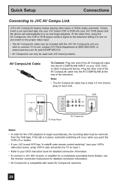
... AV CompuLink cable may be used with select AV CompuLink receivers. 20 AV COMPULINK III VIDEO (DIGITAL) _ AUDIO (DIGITAL) IN V L R IN OUT OUT TV Rear Panel AV CompuLink VCR Notes: • In order for part # EWP 805-012. • AV CompuLink can only be included with the... code/B code remote control switching" (see the receiver connection instructions for detailed connection information. • AV CompuLink is not, contact JVC Parts Department at the rear of the AV CompuLink cable into the AV COMPULINK INPUT on each end. Plug the other end of the AV CompuLink cable into ...
... AV CompuLink cable may be used with select AV CompuLink receivers. 20 AV COMPULINK III VIDEO (DIGITAL) _ AUDIO (DIGITAL) IN V L R IN OUT OUT TV Rear Panel AV CompuLink VCR Notes: • In order for part # EWP 805-012. • AV CompuLink can only be included with the... code/B code remote control switching" (see the receiver connection instructions for detailed connection information. • AV CompuLink is not, contact JVC Parts Department at the rear of the AV CompuLink cable into the AV COMPULINK INPUT on each end. Plug the other end of the AV CompuLink cable into ...

Instructions
Page 21
... OUT, into the LEFT AUDIO IN on the side of the TV. 3) Connect a red cable from the side of the TV to the L/MONO on the side of the TV. 21 L/MONO R AUDIO - OR - You can also connect these using the television's rear input jacks, using the side input jacks (Input 4) located on ... sound model it to the camcorder. 2) Connect a white cable from the camcorder LEFT AUDIO OUT, into the RIGHT AUDIO IN on the side of the TV. Connect it will have only one AUDIO OUT. INPUT MENU INPUT 4 S-VIDEO OPERATE + CHANNEL - Note: • If your television by using the same instructions. ...
... OUT, into the LEFT AUDIO IN on the side of the TV. 3) Connect a red cable from the side of the TV to the L/MONO on the side of the TV. 21 L/MONO R AUDIO - OR - You can also connect these using the television's rear input jacks, using the side input jacks (Input 4) located on ... sound model it to the camcorder. 2) Connect a white cable from the camcorder LEFT AUDIO OUT, into the RIGHT AUDIO IN on the side of the TV. Connect it will have only one AUDIO OUT. INPUT MENU INPUT 4 S-VIDEO OPERATE + CHANNEL - Note: • If your television by using the same instructions. ...

Instructions
Page 22
Connecting to an External Amplifier TV Rear Panel L AUDIO OUTPUT R Speaker Amplifier Speaker 1) Connect a white cable from the LEFT AUDIO OUTPUT on the back of the TV to the LEFT AUDIO INPUT on the amplifier. 2) Connect a red cable from the RIGHT AUDIO OUTPUT on the back of this feature... on the amplifier. Note: • Please read the benefit of the TV to the RIGHT AUDIO INPUT on page 58. By using your home theater system. 22 TV Rear Panel Front Front Surround CENTER CHANNEL INPUT L AUDIO R CENTER CHANNEL OUTPUT (VARIABLE OUTPUT) 1) Connect ...
Connecting to an External Amplifier TV Rear Panel L AUDIO OUTPUT R Speaker Amplifier Speaker 1) Connect a white cable from the LEFT AUDIO OUTPUT on the back of the TV to the LEFT AUDIO INPUT on the amplifier. 2) Connect a red cable from the RIGHT AUDIO OUTPUT on the back of this feature... on the amplifier. Note: • Please read the benefit of the TV to the RIGHT AUDIO INPUT on page 58. By using your home theater system. 22 TV Rear Panel Front Front Surround CENTER CHANNEL INPUT L AUDIO R CENTER CHANNEL OUTPUT (VARIABLE OUTPUT) 1) Connect ...

Instructions
Page 23
... You can connect an amplifier that is output can only output digital audio. • In order to your amplifier. 23 i.LINK IN/OUT S400(TS) TV Rear Panel OPTICAL OUT Digital Audio Amplifier 1) Connect the optical cable from the optical output. The signal that has an optical digital input terminal by using... an optical digital cable from the back of the amplifier. Quick Setup Connections Connecting to the back of the TV to an amplifier using your owners manual on Digital Sound in the Digital Setup Menu.
... You can connect an amplifier that is output can only output digital audio. • In order to your amplifier. 23 i.LINK IN/OUT S400(TS) TV Rear Panel OPTICAL OUT Digital Audio Amplifier 1) Connect the optical cable from the optical output. The signal that has an optical digital input terminal by using... an optical digital cable from the back of the amplifier. Quick Setup Connections Connecting to the back of the TV to an amplifier using your owners manual on Digital Sound in the Digital Setup Menu.


