
Instructions
Page 2
... to qualified service personnel. tilation is intended to alert the user to repair it yourself or remove the rear cover. WARNING: TO PREVENT FIRE OR SHOCK HAZARDS, DO NOT EXPOSE THIS TV SET TO RAIN OR MOISTURE. CAUTION: TO INSURE PERSONAL SAFETY, OBSERVE THE FOLLOWING RULES REGARDING THE USE...with arrowhead symbol, within an equilateral triangle is intended to alert the user to persons. Changes or modifications not approved by JVC could void the warranty. * When you don't use this TV set for a long period of trouble, unplug the unit and call a service technician. Do not remove cover (or...
... to qualified service personnel. tilation is intended to alert the user to repair it yourself or remove the rear cover. WARNING: TO PREVENT FIRE OR SHOCK HAZARDS, DO NOT EXPOSE THIS TV SET TO RAIN OR MOISTURE. CAUTION: TO INSURE PERSONAL SAFETY, OBSERVE THE FOLLOWING RULES REGARDING THE USE...with arrowhead symbol, within an equilateral triangle is intended to alert the user to persons. Changes or modifications not approved by JVC could void the warranty. * When you don't use this TV set for a long period of trouble, unplug the unit and call a service technician. Do not remove cover (or...

Instructions
Page 3
...refer to environmental considerations. And also follow all warnings and instructions marked on or roll over the power cord, and do not place the TV set dealer or local power company. They may result in a wet basement, or near water - for this information. For disposal or ...INFORMATION This product utilizes both a Cathode Ray Tube (CRT) and other ). (POLARIZED-TYPE) This safety feature allows the plug to assure your TV set where power cord is wider than the other components that contain lead. Call your local authorities, or the Electronic Industries Alliance: http://www...
...refer to environmental considerations. And also follow all warnings and instructions marked on or roll over the power cord, and do not place the TV set dealer or local power company. They may result in a wet basement, or near water - for this information. For disposal or ...INFORMATION This product utilizes both a Cathode Ray Tube (CRT) and other ). (POLARIZED-TYPE) This safety feature allows the plug to assure your TV set where power cord is wider than the other components that contain lead. Call your local authorities, or the Electronic Industries Alliance: http://www...

Instructions
Page 4
...to roll a cart with a cloth or other electric light or power circuits, or where it can result in the vicinity of a portable TV set from touching such power lines or circuits as contact with them might be fatal. Never block the bottom ventilation slots of overhead power ... carpets. - Wall or shelf mounting should follow the manufacturer's instructions, and should use liquid or an aerosol cleaner. 12) Never add accessories to a TV set manufacturer. - Use only a cart or stand recommended by the manufacturer. 7) An outside antenna system, extreme care should be taken to keep from ...
...to roll a cart with a cloth or other electric light or power circuits, or where it can result in the vicinity of a portable TV set from touching such power lines or circuits as contact with them might be fatal. Never block the bottom ventilation slots of overhead power ... carpets. - Wall or shelf mounting should follow the manufacturer's instructions, and should use liquid or an aerosol cleaner. 12) Never add accessories to a TV set manufacturer. - Use only a cart or stand recommended by the manufacturer. 7) An outside antenna system, extreme care should be taken to keep from ...

Instructions
Page 5
... will often require extensive work by following conditions: A. Quick stops, excessive force, and uneven surfaces may cause the TV set and cart combination should be moved with care. F. C. If the TV set . 20) Note to CATV system installer. Adjust only those controls that are required, have the same safety ...-40 of the NEC that the replacement parts he uses have the service technician verify in a picture tube implosion. SERVICE 15) Unplug this TV set to normal operation. When the power cord or plug is to be connected to the grounding system of the building, as close to ...
... will often require extensive work by following conditions: A. Quick stops, excessive force, and uneven surfaces may cause the TV set and cart combination should be moved with care. F. C. If the TV set . 20) Note to CATV system installer. Adjust only those controls that are required, have the same safety ...-40 of the NEC that the replacement parts he uses have the service technician verify in a picture tube implosion. SERVICE 15) Unplug this TV set to normal operation. When the power cord or plug is to be connected to the grounding system of the building, as close to ...

Instructions
Page 6
.... . . 32 Onscreen Menus (Continued) V-Chip 33 US Rating System 33 Viewing Guidelines 33 MPAA Ratings 34 Set Ratings Guidelines . . . . . 35 To Set TV Ratings Levels . . . . 35 To Set Movie Ratings Levels . . 36 Unrated Programs 36 Warning Message 36 Canadian V-Chip Ratings . . . 37 Set Lock Code...12 Front Panel Diagram 12 Rear Panel Diagram 12 Connecting to Cable or an Antenna . . . . 13 Cable and VCR Connections 14 Connecting to a DVD Player, DTV Decoder and D-VHS 15 Connecting to a Digital TV Receiver w/HDCP 16 Connecting to a DVD Player 17 Connecting to JVC AV Compu Link III . ....
.... . . 32 Onscreen Menus (Continued) V-Chip 33 US Rating System 33 Viewing Guidelines 33 MPAA Ratings 34 Set Ratings Guidelines . . . . . 35 To Set TV Ratings Levels . . . . 35 To Set Movie Ratings Levels . . 36 Unrated Programs 36 Warning Message 36 Canadian V-Chip Ratings . . . 37 Set Lock Code...12 Front Panel Diagram 12 Rear Panel Diagram 12 Connecting to Cable or an Antenna . . . . 13 Cable and VCR Connections 14 Connecting to a DVD Player, DTV Decoder and D-VHS 15 Connecting to a Digital TV Receiver w/HDCP 16 Connecting to a DVD Player 17 Connecting to JVC AV Compu Link III . ....

Instructions
Page 7
Table of Contents Button Functions 53 SPLIT 53 SWAP 53 FREEZE 53 SELECT 53 ENTER 53 INDEX 54 POP 54 MENU 55 EXIT 55 DISPLAY 55 SLEEP TIMER 55 BBE 56 HYPER SURROUND 56 MUTING 56 VIDEO STATUS 56 NATURAL CINEMA 56 ASPECT 56 NUMBER BUTTONS - 10 KEY PAD . . . 57 100+ BUTTON 57 RETURN 57 V-CHIP 57 INPUT 58 MENU (On TV's Front Panel 58 LIGHT 58 VCR BUTTONS 59 DVD BUTTONS 59 TV/CATV SWITCH 59 VCR/DVD SWITCH 59 Appendices 60 Troubleshooting 60 Appendix A 62 Limited Warranty 63 Authorized Service Centers 65 Specifications 66 7
Table of Contents Button Functions 53 SPLIT 53 SWAP 53 FREEZE 53 SELECT 53 ENTER 53 INDEX 54 POP 54 MENU 55 EXIT 55 DISPLAY 55 SLEEP TIMER 55 BBE 56 HYPER SURROUND 56 MUTING 56 VIDEO STATUS 56 NATURAL CINEMA 56 ASPECT 56 NUMBER BUTTONS - 10 KEY PAD . . . 57 100+ BUTTON 57 RETURN 57 V-CHIP 57 INPUT 58 MENU (On TV's Front Panel 58 LIGHT 58 VCR BUTTONS 59 DVD BUTTONS 59 TV/CATV SWITCH 59 VCR/DVD SWITCH 59 Appendices 60 Troubleshooting 60 Appendix A 62 Limited Warranty 63 Authorized Service Centers 65 Specifications 66 7

Instructions
Page 8
... use with VCRs, DVDs, Camcorders, etc (optional). AV Compu Link Cable Used to start using your purchase of...your new television, please check to make sure you 're anxious to connect JVC AV Compu Link capable components for your television right away, a quick setup guide ...DVD PREV NEXT POWER TV/VCR REW PLAY FF REC STOP PAUSE OPEN/CLOSE STILL/PAUSE Once you have all of JVC's model AV-56WP30 or AV-48WP30 Color Television. ...Television 1 Remote Control 2 AA Batteries AA Alkaline AA Alkaline JVC TV CATV VCR DVD POWER ASPECT MULTI SCREEN SPLIT POP INDEX FREEZE SWAP SELECT ENTER NATURAL...
... use with VCRs, DVDs, Camcorders, etc (optional). AV Compu Link Cable Used to start using your purchase of...your new television, please check to make sure you 're anxious to connect JVC AV Compu Link capable components for your television right away, a quick setup guide ...DVD PREV NEXT POWER TV/VCR REW PLAY FF REC STOP PAUSE OPEN/CLOSE STILL/PAUSE Once you have all of JVC's model AV-56WP30 or AV-48WP30 Color Television. ...Television 1 Remote Control 2 AA Batteries AA Alkaline AA Alkaline JVC TV CATV VCR DVD POWER ASPECT MULTI SCREEN SPLIT POP INDEX FREEZE SWAP SELECT ENTER NATURAL...

Instructions
Page 10
... 23 for VCR Cables. Proceed to 20. Cable or Antenna Output TV Rear Panel (RF Input) Cable/RF connector 75Ω (VHF / UHF) 1) Connect an RF Cable from VCR RF Cable Out into the RF Cable In on the back of the TV. Please consult the user's manual for your VCR Player for... most basic VCR and antenna/cable connection is required, or connecting with a combination of TV 1) Connect the Red Cable from VCR Audio Output into the Red TV Audio In. 2) Connect the White Cable from VCR Audio Output into the White TV Audio In. 3) Connect the Yellow Cable from VCR Output into the Yellow...
... 23 for VCR Cables. Proceed to 20. Cable or Antenna Output TV Rear Panel (RF Input) Cable/RF connector 75Ω (VHF / UHF) 1) Connect an RF Cable from VCR RF Cable Out into the RF Cable In on the back of the TV. Please consult the user's manual for your VCR Player for... most basic VCR and antenna/cable connection is required, or connecting with a combination of TV 1) Connect the Red Cable from VCR Audio Output into the Red TV Audio In. 2) Connect the White Cable from VCR Audio Output into the White TV Audio In. 3) Connect the Yellow Cable from VCR Output into the Yellow...
Instructions
Page 13
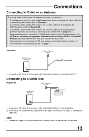
Diagram #1 TV Rear Panel (RF Input) Cable or Antenna Output Cable/RF connector 75Ω (VHF / UHF) 1)...instructions on connecting a VCR only, please see the Quick Setup on page 10. • For information on the back of the TV. Connecting to a VCR is also shown in the following diagrams. A VCR is not necessary for more information on using POP,... see page 54. You may omit the VCR from your convenience, connection to a Cable Box Diagram #2 Cable or Antenna Output TV Rear Panel (RF Input) Cable Box OUT IN 75Ω (VHF / UHF) 1) Connect an RF Cable from the wall outlet...
Diagram #1 TV Rear Panel (RF Input) Cable or Antenna Output Cable/RF connector 75Ω (VHF / UHF) 1)...instructions on connecting a VCR only, please see the Quick Setup on page 10. • For information on the back of the TV. Connecting to a VCR is also shown in the following diagrams. A VCR is not necessary for more information on using POP,... see page 54. You may omit the VCR from your convenience, connection to a Cable Box Diagram #2 Cable or Antenna Output TV Rear Panel (RF Input) Cable Box OUT IN 75Ω (VHF / UHF) 1) Connect an RF Cable from the wall outlet...
Instructions
Page 14
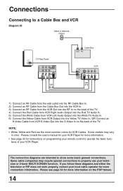
Connections Connecting to a Cable Box and VCR Diagram #3 Cable or Antenna Output 75Ω (VHF / UHF) TV Rear Panel INPUT-3 INPUT-2 OVER INPUT-1 AUDIO OVER VIDEO S-VIDEO OR Cable Box OUT IN IN OUT VCR V L R V L R OR 1) Connect an RF Cable from the wall ... In, OR Connect an S-Video Cable from VCR S-Video Out into the S-Video In on the back of your VCR Player. tions of the TV. Some cable companies may vary in color. Please see page 54 for more information. • See page 23 for instructions on the POP feature. 14 ...
Connections Connecting to a Cable Box and VCR Diagram #3 Cable or Antenna Output 75Ω (VHF / UHF) TV Rear Panel INPUT-3 INPUT-2 OVER INPUT-1 AUDIO OVER VIDEO S-VIDEO OR Cable Box OUT IN IN OUT VCR V L R V L R OR 1) Connect an RF Cable from the wall ... In, OR Connect an S-Video Cable from VCR S-Video Out into the S-Video In on the back of your VCR Player. tions of the TV. Some cable companies may vary in color. Please see page 54 for more information. • See page 23 for instructions on the POP feature. 14 ...

Instructions
Page 15
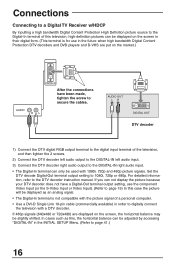
... Video) before starting the other to the TV. 15 It is HDTV and SDTV-Ready. For High Definition (HDTV) picture display a DTV decoder must be connected to avoid accidentally switching the cables. * Notes About HDTV Operation The AV-56WP30 or AV-48WP30 can display High Definition television images when...separately. Connections Connecting a DVD Player, DTV Decoder, and D-VHS Your AV-56WP30 or AV-48WP30 television is best to complete one set of TV 1) Connect Green cable out from the DTV Decoder "Y" Video Output, in to TV "Y" Component Input. 2) Connect Blue cable out from the DTV Decoder...
... Video) before starting the other to the TV. 15 It is HDTV and SDTV-Ready. For High Definition (HDTV) picture display a DTV decoder must be connected to avoid accidentally switching the cables. * Notes About HDTV Operation The AV-56WP30 or AV-48WP30 can display High Definition television images when...separately. Connections Connecting a DVD Player, DTV Decoder, and D-VHS Your AV-56WP30 or AV-48WP30 television is best to complete one set of TV 1) Connect Green cable out from the DTV Decoder "Y" Video Output, in to TV "Y" Component Input. 2) Connect Blue cable out from the DTV Decoder...
Instructions
Page 16
... can be adjusted by accessing "DIGITAL-IN" in order to digitally connect the television with 1080i, 720p and 480p picture signals. Connections Connecting to a Digital TV Receiver w/HDCP By inputting a high bandwidth Digital Content Protection High Definition picture source to the Digital-In terminal of this television, high-definition pictures can...
... can be adjusted by accessing "DIGITAL-IN" in order to digitally connect the television with 1080i, 720p and 480p picture signals. Connections Connecting to a Digital TV Receiver w/HDCP By inputting a high bandwidth Digital Content Protection High Definition picture source to the Digital-In terminal of this television, high-definition pictures can...

Instructions
Page 17
...Component Input 3, also use Audio Input 3. • Green, blue and red are the most common colors for more information. • Be careful not to TV Right Audio Input. See your television. To connect a DVD player, please follow the steps listed below. 1) Connect Green cable out from the DVD Player ..."Y" Video Output, in to TV "Y" Component Input. 2) Connect Blue cable out from the DVD Player "PB" Video Output, in to confuse the red Component Video cable with the red ...
...Component Input 3, also use Audio Input 3. • Green, blue and red are the most common colors for more information. • Be careful not to TV Right Audio Input. See your television. To connect a DVD player, please follow the steps listed below. 1) Connect Green cable out from the DVD Player ..."Y" Video Output, in to TV "Y" Component Input. 2) Connect Blue cable out from the DVD Player "PB" Video Output, in to confuse the red Component Video cable with the red ...

Instructions
Page 18
... Link III can only be used with all JVC AV COMPU LINK III devices • The AV-56WP30 or AV-48WP30 can also receive Compu-Link signals from a DVD player. Simply insert a pre-recorded tape* into the AV Compu Link input at the rear of the AV Compu Link cable into your cable box, use Input 1 for...switch to the proper video input to watch a video tape. • The AV Compu Link cable may be removed from your JVC-brand VCR and the VCR will switch the TV to the television telling it is compatible with JVC-brand products. If the tab is in place, automatic switching will occur when...
... Link III can only be used with all JVC AV COMPU LINK III devices • The AV-56WP30 or AV-48WP30 can also receive Compu-Link signals from a DVD player. Simply insert a pre-recorded tape* into the AV Compu Link input at the rear of the AV Compu Link cable into your cable box, use Input 1 for...switch to the proper video input to watch a video tape. • The AV Compu Link cable may be removed from your JVC-brand VCR and the VCR will switch the TV to the television telling it is compatible with JVC-brand products. If the tab is in place, automatic switching will occur when...

Instructions
Page 19
... its operation. 19 To connect a device like camcorders or game consoles which are not permanent parts of your home entertainment center. - Connect it to the TV's left audio input jack. • The device will have only one audio out jack. These inputs are designed for the easy connection of devices like... information on the door torwards you to the Front Panel Inputs A set of inputs (Input-4) are located behind the door at the center of the AV-56WP30 or AV-48WP30. OR - Connections Connecting Devices to open it.
... its operation. 19 To connect a device like camcorders or game consoles which are not permanent parts of your home entertainment center. - Connect it to the TV's left audio input jack. • The device will have only one audio out jack. These inputs are designed for the easy connection of devices like... information on the door torwards you to the Front Panel Inputs A set of inputs (Input-4) are located behind the door at the center of the AV-56WP30 or AV-48WP30. OR - Connections Connecting Devices to open it.
Instructions
Page 20
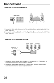
... amplifier's center speaker output terminal. 2) Connect the RED speaker cable from the TV's Right Audio Output Jack to the surround amplifier's center speaker output terminal. 20 Connections Connecting to an External Amplifier TV Rear Panel R L AUDIO OUT AUDIO R L INPUT 3 INPUT 2 OVER INPUT ...1 R L AUDIO OVER VIDEO S-VIDEO Left Front Speaker Amplifier Right Front Speaker 1) Connect the White Audio Cable from the TV's Left Audio Output Jack to the ...
... amplifier's center speaker output terminal. 2) Connect the RED speaker cable from the TV's Right Audio Output Jack to the surround amplifier's center speaker output terminal. 20 Connections Connecting to an External Amplifier TV Rear Panel R L AUDIO OUT AUDIO R L INPUT 3 INPUT 2 OVER INPUT ...1 R L AUDIO OVER VIDEO S-VIDEO Left Front Speaker Amplifier Right Front Speaker 1) Connect the White Audio Cable from the TV's Left Audio Output Jack to the ...
Instructions
Page 21
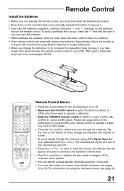
... VCR DVD POWER ASPECT MULTI SCREEN SPLIT POP INDEX FREEZE SWAP SELECT ENTER NATURAL CINEMA 1 INPUT 4 DISPLAY 7 SLEEP TIMER 100+ 23 56 89 0 RETURN+ BBE V. For information on using the 10-key pad. • For more information on the remote control. To avoid a potential short ... longer than three minutes, the remote control codes for instructions on or off. • Make sure the TV/CATV switch is six months to move rapidly through the channels. We recommend using JVC's Hyper Scan feature, press and hold CH+ or CH-. Tap the CH+ or CH- buttons are installed...
... VCR DVD POWER ASPECT MULTI SCREEN SPLIT POP INDEX FREEZE SWAP SELECT ENTER NATURAL CINEMA 1 INPUT 4 DISPLAY 7 SLEEP TIMER 100+ 23 56 89 0 RETURN+ BBE V. For information on using the 10-key pad. • For more information on the remote control. To avoid a potential short ... longer than three minutes, the remote control codes for instructions on or off. • Make sure the TV/CATV switch is six months to move rapidly through the channels. We recommend using JVC's Hyper Scan feature, press and hold CH+ or CH-. Tap the CH+ or CH- buttons are installed...

Instructions
Page 23
...Find the VCR brand from the list of codes shown below. 2) Slide the first 2-way selector switch to "TV" and the other buttons work properly. • To record, hold down the DISPLAY button. 4) With the ...hold down the REC button on page 25. • Some manufacturer's VCR's may not respond to the TV/VCR button, even if other 2-way selector switch to the first code, try the others listed. VCRs...083, 084, 081, 000, 001 Hitachi 023, 045, 058, 027, 081, 093 Instant Replay 024, 023 Jensen 003 JVC 000, 001, 002, 003, 004, 005 Kenwood LXI 003, 004, 064, 005 027, 064, 058, 065, 066,...
...Find the VCR brand from the list of codes shown below. 2) Slide the first 2-way selector switch to "TV" and the other buttons work properly. • To record, hold down the DISPLAY button. 4) With the ...hold down the REC button on page 25. • Some manufacturer's VCR's may not respond to the TV/VCR button, even if other 2-way selector switch to the first code, try the others listed. VCRs...083, 084, 081, 000, 001 Hitachi 023, 045, 058, 027, 081, 093 Instant Replay 024, 023 Jensen 003 JVC 000, 001, 002, 003, 004, 005 Kenwood LXI 003, 004, 064, 005 027, 064, 058, 065, 066,...
Instructions
Page 24
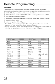
... open/close, and still/pause operation. 1) Find the DVD player brand from the list of codes shown below. 2) Slide the first 2-way selector switch to "TV" and the other 2-way selector switch to "DVD". 3) Press and hold down the DISPLAY button. 4) With the DISPLAY button held down, enter the first code... remote, some buttons do not work properly. If it does not respond to any code, try the others listed. DVD Player Aiwa Apex Denon Hitachi JVC Kenwood Konka Mitsubishi Onkyo Oritron Panasonic Philips Pioneer CODES 043 040 020, 037 030, 031 000 035 039 025 041 044 020 023, 036 022...
... open/close, and still/pause operation. 1) Find the DVD player brand from the list of codes shown below. 2) Slide the first 2-way selector switch to "TV" and the other 2-way selector switch to "DVD". 3) Press and hold down the DISPLAY button. 4) With the DISPLAY button held down, enter the first code... remote, some buttons do not work properly. If it does not respond to any code, try the others listed. DVD Player Aiwa Apex Denon Hitachi JVC Kenwood Konka Mitsubishi Onkyo Oritron Panasonic Philips Pioneer CODES 043 040 020, 037 030, 031 000 035 039 025 041 044 020 023, 036 022...

Instructions
Page 25
Hold for at least three seconds and release. 3) Press TV POWER, see if the CATV or Satellite box responds. 4) If there was no response, repeat Step 3. If... which came with the equipment. 5) Press RETURN+ to exit. VCR Search Codes Function: 1) Slide the first 2-way selector switch to "TV" and the other 2-way selector switch to exit. 25 If there was a response, press RETURN+. The operating codes are now set ...no response, repeat Step 3. DVD Player Search Codes Function: 1) Slide the first 2-way selector switch to "TV" and the other 2-way selector switch to CATV. 2) Press the...
Hold for at least three seconds and release. 3) Press TV POWER, see if the CATV or Satellite box responds. 4) If there was no response, repeat Step 3. If... which came with the equipment. 5) Press RETURN+ to exit. VCR Search Codes Function: 1) Slide the first 2-way selector switch to "TV" and the other 2-way selector switch to exit. 25 If there was a response, press RETURN+. The operating codes are now set ...no response, repeat Step 3. DVD Player Search Codes Function: 1) Slide the first 2-way selector switch to "TV" and the other 2-way selector switch to CATV. 2) Press the...


