User Guide
Page 25
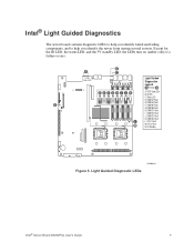
... N DE FGH I . ID LED C. DIMM A2 Fault N F. DIMM C1 Fault I J K A. CPU 2 Fault N. 5V Standby CPU 2 CPU 1 Socket Socket Figure 5. DIMM B2 Fault H. POST Code LEDs B. DIMM C2 Fault J. DIMM D1 Fault K. Light Guided Diagnostic LEDs AF000644 Intel® Server Board S5000PAL User's Guide 7 DIMM A1 Fault E. CPU 1 Fault M M. DIMM B1 Fault DIMM A1 DIMM A2 DIMM B1 DIMM...
... N DE FGH I . ID LED C. DIMM A2 Fault N F. DIMM C1 Fault I J K A. CPU 2 Fault N. 5V Standby CPU 2 CPU 1 Socket Socket Figure 5. DIMM B2 Fault H. POST Code LEDs B. DIMM C2 Fault J. DIMM D1 Fault K. Light Guided Diagnostic LEDs AF000644 Intel® Server Board S5000PAL User's Guide 7 DIMM A1 Fault E. CPU 1 Fault M M. DIMM B1 Fault DIMM A1 DIMM A2 DIMM B1 DIMM...

User Guide
Page 42
... the Processor Socket Handle 6. they are very sensitive and easily damaged. 24 "Intel® Server Board S5000PAL User's Guide" Raise the CPU load plate (see Figure 12). TP02074 Figure 12. Installing the Processor To install a processor, follow these instructions: 1. Installing the Processor Note: Do not touch the ...
... the Processor Socket Handle 6. they are very sensitive and easily damaged. 24 "Intel® Server Board S5000PAL User's Guide" Raise the CPU load plate (see Figure 12). TP02074 Figure 12. Installing the Processor To install a processor, follow these instructions: 1. Installing the Processor Note: Do not touch the ...

User Guide
Page 43
Note: Make sure the alignment triangle mark and the alignment triangle cutout align correctly. 8. Note: Retain the protective socket cover for use when removing a processor that will not be replaced. Lower the CPU load plate and lower the socket lever completely. 7. Line up the alignment marks on the processor and the socket, and insert the processor into the socket. A B TP02076 Figure 14. Remove the protective socket cover (see Figure 14). "Intel® Server Board S5000PAL User's Guide" 25 Removing the Socket Cover 9.
Note: Make sure the alignment triangle mark and the alignment triangle cutout align correctly. 8. Note: Retain the protective socket cover for use when removing a processor that will not be replaced. Lower the CPU load plate and lower the socket lever completely. 7. Line up the alignment marks on the processor and the socket, and insert the processor into the socket. A B TP02076 Figure 14. Remove the protective socket cover (see Figure 14). "Intel® Server Board S5000PAL User's Guide" 25 Removing the Socket Cover 9.

User Guide
Page 45
...easily, twist the heat sink again. Do not force the heat sink from the server. 4. Doing so could damage the processor. 9. "Intel® Server Board S5000PAL User's Guide" 27 Remove the server's cover. Raise the CPU load plate. 11. If installing a replacement processor, see "Installing the Processor". ...a Processor 1. Remove the AC power cord from the processor. Loosen the four captive screws on removing the server's cover. 5. Lift the heat sink from the server board. 6. Lift the processor lever. 10. Remove the processor. 12. Turn off all peripheral devices connected to...
...easily, twist the heat sink again. Do not force the heat sink from the server. 4. Doing so could damage the processor. 9. "Intel® Server Board S5000PAL User's Guide" 27 Remove the server's cover. Raise the CPU load plate. 11. If installing a replacement processor, see "Installing the Processor". ...a Processor 1. Remove the AC power cord from the processor. Loosen the four captive screws on removing the server's cover. 5. Lift the heat sink from the server board. 6. Lift the processor lever. 10. Remove the processor. 12. Turn off all peripheral devices connected to...

User Guide
Page 69
... Table 9. No processor is installed or the CPU 1 socket is empty. DC power unexpectedly lost. Front-side bus select configuration error. Intel® Server Board S5000PAL User's Guide 51 The Intel® Remote Management Module provides the following additional ...beep codes. Error Beep Codes Generated by Intel® Remote Management Module Number of Beeps 1 1-5-1-1 1-5-2-1 ...
... Table 9. No processor is installed or the CPU 1 socket is empty. DC power unexpectedly lost. Front-side bus select configuration error. Intel® Server Board S5000PAL User's Guide 51 The Intel® Remote Management Module provides the following additional ...beep codes. Error Beep Codes Generated by Intel® Remote Management Module Number of Beeps 1 1-5-1-1 1-5-2-1 ...


