
Service Guide
Page 9
... Connector and Component Locations (S1200V3RPL and S1200V3RPS)..... 8 Figure 9. Installing Processor - Installing 3.5" HDD 38 Figure 42. Connecting the Fan Power Cables to the Motherboard 28 Figure 23. Open the Load Plate 33 Figure 32. Remove the Cover 35 Figure 37. Installing Hard Disk Drive - Intel® Server System R1000RP Components 4 Figure 3. 3.5" Fixed Hard Drive Bay...
... Connector and Component Locations (S1200V3RPL and S1200V3RPS)..... 8 Figure 9. Installing Processor - Installing 3.5" HDD 38 Figure 42. Connecting the Fan Power Cables to the Motherboard 28 Figure 23. Open the Load Plate 33 Figure 32. Remove the Cover 35 Figure 37. Installing Hard Disk Drive - Intel® Server System R1000RP Components 4 Figure 3. 3.5" Fixed Hard Drive Bay...
Technical Product Specification
Page 37
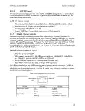
... Access Control (MAC) and Physical Layer (PHY) port. The LED at the right of the connector indicates link speed as a LAN on Motherboard (LOM) design. Intel® Server Board S1200V3RP Functional Architecture 3.4.6.3 eUSB SSD Support The server board provides support for Boot capability 3.4.7 Gigabit Ethernet Controller Network connectivity is provided by means of two onboard...
... Access Control (MAC) and Physical Layer (PHY) port. The LED at the right of the connector indicates link speed as a LAN on Motherboard (LOM) design. Intel® Server Board S1200V3RP Functional Architecture 3.4.6.3 eUSB SSD Support The server board provides support for Boot capability 3.4.7 Gigabit Ethernet Controller Network connectivity is provided by means of two onboard...

Technical Product Specification
Page 215
... functionality is to indicate BMC boot process transitions and states. The purpose of these LEDs are located on replacing this motherboard. The following table defines the LED states during the POST process. Nonrecoverable condition. Normal system operation ID LED Solid Blue...diagnostic LEDs. See Appendix D for ~10-~20 seconds. Server will occur when AC power is started, the BIOS displays the given POST code to the stacked USB connectors. Table 60. Intel® Server Board S1200V3RP Intel® Light Guided Diagnostics Color State Criticality Description 240VA ...
... functionality is to indicate BMC boot process transitions and states. The purpose of these LEDs are located on replacing this motherboard. The following table defines the LED states during the POST process. Nonrecoverable condition. Normal system operation ID LED Solid Blue...diagnostic LEDs. See Appendix D for ~10-~20 seconds. Server will occur when AC power is started, the BIOS displays the given POST code to the stacked USB connectors. Table 60. Intel® Server Board S1200V3RP Intel® Light Guided Diagnostics Color State Criticality Description 240VA ...

Technical Product Specification
Page 64
... PCI Express* Gen2 x8 PCI Express* Gen2 x4 PCI Express* Gen2 x4 54 Intel order number: G91532-003 Revision 1.2 Intel® Server System R1304RPSSFBN provides one PCI Express* x8 slot through Riser card S1200V3RPS R1304RPSSFBN PCI Express* Gen3 x8 on the three motherboards and the mapping to the systems. Table 29. PCI Express* Speed Matrix...
... PCI Express* Gen2 x8 PCI Express* Gen2 x4 PCI Express* Gen2 x4 54 Intel order number: G91532-003 Revision 1.2 Intel® Server System R1304RPSSFBN provides one PCI Express* x8 slot through Riser card S1200V3RPS R1304RPSSFBN PCI Express* Gen3 x8 on the three motherboards and the mapping to the systems. Table 29. PCI Express* Speed Matrix...
