Design Guidelines
Page 6
Package IHS Load Areas 17 Figure 2. Processor Thermal Characterization Parameter Relationships 30 Figure 5. Thermal Monitor 2 Frequency and Voltage Ordering 38 Figure 9. Exploded View 43 Figure 11. Random Vibration PSD 49 Figure 14. PID Controller Fundamentals 59 Figure 21....Copper Core Applied by TC-1996 Grease 45 Figure 13. Thermocouple Placed into Groove 94 Figure 50. Example Thermal Profile 23 Figure 4. Positioning Solder on the 775-LAND LGA Package 83 Figure 33. Figures Figure 1. IHS Groove at 3 o'clock Exit (Old Drawing 81 Figure 32. Intel ...
Package IHS Load Areas 17 Figure 2. Processor Thermal Characterization Parameter Relationships 30 Figure 5. Thermal Monitor 2 Frequency and Voltage Ordering 38 Figure 9. Exploded View 43 Figure 11. Random Vibration PSD 49 Figure 14. PID Controller Fundamentals 59 Figure 21....Copper Core Applied by TC-1996 Grease 45 Figure 13. Thermocouple Placed into Groove 94 Figure 50. Example Thermal Profile 23 Figure 4. Positioning Solder on the 775-LAND LGA Package 83 Figure 33. Figures Figure 1. IHS Groove at 3 o'clock Exit (Old Drawing 81 Figure 32. Intel ...
Design Guidelines
Page 35
...voltage, reducing unnecessary transistor activity, and using a highly accurate on the processor. It provides a thermal management approach to reduce the power consumption of a processor, and Intel is aggressively pursuing low power design techniques. The processor also supports an additional power reduction capability known as Thermal Monitor 2 described in processor... linearly with frequency and with power dissipations in processors with the square of the following equation: P = CV2F (where P = power, C = capacitance, V = voltage, F = frequency). Thermal Management Logic and ...
...voltage, reducing unnecessary transistor activity, and using a highly accurate on the processor. It provides a thermal management approach to reduce the power consumption of a processor, and Intel is aggressively pursuing low power design techniques. The processor also supports an additional power reduction capability known as Thermal Monitor 2 described in processor... linearly with frequency and with power dissipations in processors with the square of the following equation: P = CV2F (where P = power, C = capacitance, V = voltage, F = frequency). Thermal Management Logic and ...
Design Guidelines
Page 36
...), and the PROCHOT# output pin are two methods by reducing the processor power consumption. It is for the thermal protection of voltage regulators (VR). As an input, assertion of PROCHOT# will disable the internal clocks for both cores. Bi-directional PROCHOT# can reduce processor power dissipation. Note: A thermal solution designed to operate within the...
...), and the PROCHOT# output pin are two methods by reducing the processor power consumption. It is for the thermal protection of voltage regulators (VR). As an input, assertion of PROCHOT# will disable the internal clocks for both cores. Bi-directional PROCHOT# can reduce processor power dissipation. Note: A thermal solution designed to operate within the...

Design Guidelines
Page 37
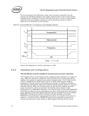
... TM2 includes two operating points, each consisting of reducing the power consumption within the processor and limiting the processor temperature. Once the new operating frequency is engaged, the processor will transition to the new core operating voltage by dropping the bus-to-core multiplier to service any bus requests, all bus traffic is TM2. The second...
... TM2 includes two operating points, each consisting of reducing the power consumption within the processor and limiting the processor temperature. Once the new operating frequency is engaged, the processor will transition to the new core operating voltage by dropping the bus-to-core multiplier to service any bus requests, all bus traffic is TM2. The second...
Design Guidelines
Page 38
... be configured and monitored in an MSR (model specific register). Thermal Management Logic and Thermal Monitor Feature Once the processor has sufficiently cooled, and a minimum activation time has expired, the operating frequency and voltage transition back to Figure 8 for an illustration of this ordering. The Thermal Control Circuit feature can be enabled...
... be configured and monitored in an MSR (model specific register). Thermal Management Logic and Thermal Monitor Feature Once the processor has sufficiently cooled, and a minimum activation time has expired, the operating frequency and voltage transition back to Figure 8 for an illustration of this ordering. The Thermal Control Circuit feature can be enabled...

Design Guidelines
Page 48
...a temperature of 57,000 hours. In addition to passing the environmental reliability tests described in fan PWM signal current source PWM signal maximum voltage for logic low PWM compliant function Value 1.5 A 2.2 A 1.0 second 12 V ±5% 2 pulse per revolution Open-collector (open-drain)...and Mechanical Design Guidelines See the Fan Specification for 4-wire PWM Controlled Fans for proper operation are given Table 7. Intel® Thermal/Mechanical Reference Design Information 5.2.5 Fan Performance for Active Heatsink Thermal Solution The fan power requirements for additional ...
...a temperature of 57,000 hours. In addition to passing the environmental reliability tests described in fan PWM signal current source PWM signal maximum voltage for logic low PWM compliant function Value 1.5 A 2.2 A 1.0 second 12 V ±5% 2 pulse per revolution Open-collector (open-drain)...and Mechanical Design Guidelines See the Fan Specification for 4-wire PWM Controlled Fans for proper operation are given Table 7. Intel® Thermal/Mechanical Reference Design Information 5.2.5 Fan Performance for Active Heatsink Thermal Solution The fan power requirements for additional ...

Design Guidelines
Page 60
... 6.2 Board and System Implementation of Intel® Quiet System Technology To implement the board must be configured as shown in the ICH8 to provide additional thermal and voltage sensing capability to provide board thermal data for the Intel QST Firmware SST-based... thermal sensors to the Manageability Engine (ME) 60 Thermal and Mechanical Design Guidelines Intel® Quiet System Technology Platform Requirements Processor Intel® (G)MCH MMEE DRAM DRAM Intel®...
... 6.2 Board and System Implementation of Intel® Quiet System Technology To implement the board must be configured as shown in the ICH8 to provide additional thermal and voltage sensing capability to provide board thermal data for the Intel QST Firmware SST-based... thermal sensors to the Manageability Engine (ME) 60 Thermal and Mechanical Design Guidelines Intel® Quiet System Technology Platform Requirements Processor Intel® (G)MCH MMEE DRAM DRAM Intel®...

Design Guidelines
Page 61
...Intel® Core™2 Duo. In this configuration a SST Thermal Sensor has been added to read the on-die thermal diode that can be added to provide devices for the SST bus. With the proper configuration information the ME can support processors with a number of major manufacturers of the processors in all of thermal / voltage... sensors to monitor system thermal (see Appendix E for BTX recommendations for your design. Contact your Intel Field Sales representative for ...
...Intel® Core™2 Duo. In this configuration a SST Thermal Sensor has been added to read the on-die thermal diode that can be added to provide devices for the SST bus. With the proper configuration information the ME can support processors with a number of major manufacturers of the processors in all of thermal / voltage... sensors to monitor system thermal (see Appendix E for BTX recommendations for your design. Contact your Intel Field Sales representative for ...

Design Guidelines
Page 62
...VSF curve. See your Intel field sales representative for fan control, fan monitoring, voltage and thermal monitoring. This Variable Speed Fan curve will determine the maximum fan speed as a function of the inlet ambient temperature and by measuring the processor digital thermal sensor will ...PWM Duty Cycle) Min. Operating Fan Speed Operating Range with the hardware configuration of the processor. A Weighting Matrix Utility and Intel QST Log program are planned to assist in tandem to processor workload. Care needs to be used again but they can be programmed with FSC Min...
...VSF curve. See your Intel field sales representative for fan control, fan monitoring, voltage and thermal monitoring. This Variable Speed Fan curve will determine the maximum fan speed as a function of the inlet ambient temperature and by measuring the processor digital thermal sensor will ...PWM Duty Cycle) Min. Operating Fan Speed Operating Range with the hardware configuration of the processor. A Weighting Matrix Utility and Intel QST Log program are planned to assist in tandem to processor workload. Care needs to be used again but they can be programmed with FSC Min...