

Design Guidelines
Page 3
...19 2.1.2.2 Heatsink Clip Load Requirement 19 2.1.2.3 Additional Guidelines 20 2.2 Thermal Requirements 20 2.2.1 Processor Case Temperature 20 2.2.2 Thermal Profile 21 2.2.3 TCONTROL 23 2.3 Heatsink Design Considerations 24 2.3.1 Heatsink Size ... Requirements 29 3.1.1 Example 31 3.2 Processor Thermal Solution Performance Assessment 31 3.3 Local Ambient Temperature Measurement Guidelines 32 3.4 Processor Case Temperature Measurement Guidelines 34 4 Thermal Management Logic and Thermal Monitor Feature 35 4.1 Processor Power Dissipation 35 4.2 Thermal Monitor Implementation...
...19 2.1.2.2 Heatsink Clip Load Requirement 19 2.1.2.3 Additional Guidelines 20 2.2 Thermal Requirements 20 2.2.1 Processor Case Temperature 20 2.2.2 Thermal Profile 21 2.2.3 TCONTROL 23 2.3 Heatsink Design Considerations 24 2.3.1 Heatsink Size ... Requirements 29 3.1.1 Example 31 3.2 Processor Thermal Solution Performance Assessment 31 3.3 Local Ambient Temperature Measurement Guidelines 32 3.4 Processor Case Temperature Measurement Guidelines 34 4 Thermal Management Logic and Thermal Monitor Feature 35 4.1 Processor Power Dissipation 35 4.2 Thermal Monitor Implementation...

Design Guidelines
Page 5
...Preload Degradation under Bake Conditions 73 Thermal Interface Management 75 C.1 Bond Line Management 75 C.2 Interface Material Area 75 C.3 Interface Material Performance 75 Case Temperature Reference Metrology 77 D.1 Objective and Scope 77 D.2 Supporting Test Equipment 77 D.3 Thermal calibration and controls 78 D.4 IHS Groove 79 D.5 Thermocouple Attach... 96 Balanced Technology Extended (BTX) System Thermal Considerations 99 Appendix F Mechanical Drawings 103 Appendix G Intel® Enabled Reference Solution Information 123 Thermal and Mechanical Design Guidelines 5
...Preload Degradation under Bake Conditions 73 Thermal Interface Management 75 C.1 Bond Line Management 75 C.2 Interface Material Area 75 C.3 Interface Material Performance 75 Case Temperature Reference Metrology 77 D.1 Objective and Scope 77 D.2 Supporting Test Equipment 77 D.3 Thermal calibration and controls 78 D.4 IHS Groove 79 D.5 Thermocouple Attach... 96 Balanced Technology Extended (BTX) System Thermal Considerations 99 Appendix F Mechanical Drawings 103 Appendix G Intel® Enabled Reference Solution Information 123 Thermal and Mechanical Design Guidelines 5
Design Guidelines
Page 6
Thermal Monitor Control 37 Figure 8. Exploded View 43 Figure 11. Intel D60188-001 Reference Design ─ Exploded View 44 Figure 12. Critical Core Dimension 55 Figure 19. Digital Thermal Sensor and Thermistor 62 Figure 24. Load Cell Installation in Machined ... Bead 89 Figure 43. Upward Board Deflection During Shock 53 Figure 16. Moving Solder back onto Thermocouple Bead 92 Figure 48. Processor Case Temperature Measurement Location 21 Figure 3. Example Thermal Profile 23 Figure 4. Load Cell Installation in Machined Heatsink Base Pocket (Bottom View) ...70...
Thermal Monitor Control 37 Figure 8. Exploded View 43 Figure 11. Intel D60188-001 Reference Design ─ Exploded View 44 Figure 12. Critical Core Dimension 55 Figure 19. Digital Thermal Sensor and Thermistor 62 Figure 24. Load Cell Installation in Machined ... Bead 89 Figure 43. Upward Board Deflection During Shock 53 Figure 16. Moving Solder back onto Thermocouple Bead 92 Figure 48. Processor Case Temperature Measurement Location 21 Figure 3. Example Thermal Profile 23 Figure 4. Load Cell Installation in Machined Heatsink Base Pocket (Bottom View) ...70...

Design Guidelines
Page 8
... Reference Thermal Solution Providers 124 Table 13. Acoustic Results for 775_VR_CONFIG 05B Processors 45 Table 4. Board Deflection Configuration Definitions 64 Table 9. Heatsink Inlet Temperature of RCFH-4 and BTX 123 Table 11. Intel® Representative Contact for Licensing Information of Intel® Boxed Processor thermal solutions .....27 Table 3. RCFH-4 Reference Thermal Solution Providers 123 Table 12...
... Reference Thermal Solution Providers 124 Table 13. Acoustic Results for 775_VR_CONFIG 05B Processors 45 Table 4. Board Deflection Configuration Definitions 64 Table 9. Heatsink Inlet Temperature of RCFH-4 and BTX 123 Table 11. Intel® Representative Contact for Licensing Information of Intel® Boxed Processor thermal solutions .....27 Table 3. RCFH-4 Reference Thermal Solution Providers 123 Table 12...
Design Guidelines
Page 11
... the physical constraints at and above the processor. The result is an increased importance on single processor systems using the Intel® Core™2 Extreme quad-core processor QX6000 series, Intel® Core™2 Quad processor Q6000 series, Intel® Core™2 Quad processor Q9000 and Q8000series, and Intel® Core™2 Extreme processor QX9650. The goal of this temperature range, a component is expected to meet...
... the physical constraints at and above the processor. The result is an increased importance on single processor systems using the Intel® Core™2 Extreme quad-core processor QX6000 series, Intel® Core™2 Quad processor Q6000 series, Intel® Core™2 Quad processor Q9000 and Q8000series, and Intel® Core™2 Extreme processor QX9650. The goal of this temperature range, a component is expected to meet...
Design Guidelines
Page 13
... Processor QX9000 Series and Intel® Core™2 Quad Processor Q9000, Q9000S, Q8000, and Q8000SSeries Datasheet Intel® Core™2 Duo Processor E8000 and E7000 Series and Intel® Pentium® Dual-Core Processor E5000 Series Thermal and Mechanical Design Guide LGA775 Socket Mechanical Design Guide Fan Specification for the product dimensions, thermal power dissipation and maximum case temperature...
... Processor QX9000 Series and Intel® Core™2 Quad Processor Q9000, Q9000S, Q8000, and Q8000SSeries Datasheet Intel® Core™2 Duo Processor E8000 and E7000 Series and Intel® Pentium® Dual-Core Processor E5000 Series Thermal and Mechanical Design Guide LGA775 Socket Mechanical Design Guide Fan Specification for the product dimensions, thermal power dissipation and maximum case temperature...
Design Guidelines
Page 14
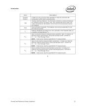
... to improve heat transfer to a system chassis. The maximum power dissipated by lowering effective processor frequency when the die temperature has exceeded its operating limits. The measured ambient temperature locally surrounding the processor. Thermal Control Circuit: Thermal Monitor uses the TCC to form a duct. Thermal Design Power: A power dissipation target based on -die thermal...
... to improve heat transfer to a system chassis. The maximum power dissipated by lowering effective processor frequency when the die temperature has exceeded its operating limits. The measured ambient temperature locally surrounding the processor. Thermal Control Circuit: Thermal Monitor uses the TCC to form a duct. Thermal Design Power: A power dissipation target based on -die thermal...
Design Guidelines
Page 15
...the transfer of thermal interface material performance using total package power. Defined as (TC - A measure of the heat from the processor case to the heatsink. Defined as (TS - Introduction Term Thermal Monitor TIM TMA TS CA CS ... compound between the heatsink and the processor case. TS) / Total Package Power. Case-to keep the processor die temperature within factory specifications. NOTE: Heat source must be specified for the BTX thermal solution Heatsink temperature measured on the processor that attempts to -ambient thermal characterization...
...the transfer of thermal interface material performance using total package power. Defined as (TC - A measure of the heat from the processor case to the heatsink. Defined as (TS - Introduction Term Thermal Monitor TIM TMA TS CA CS ... compound between the heatsink and the processor case. TS) / Total Package Power. Case-to keep the processor die temperature within factory specifications. NOTE: Heat source must be specified for the BTX thermal solution Heatsink temperature measured on the processor that attempts to -ambient thermal characterization...
Design Guidelines
Page 19
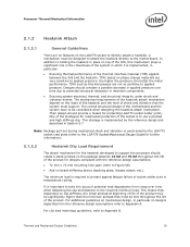
...mechanism for designs compliant with the reference design assumptions: 72 mm x 72 mm mounting hole span (refer to Appendix A. Processor Thermal/Mechanical Information 2.1.2 Heatsink Attach 2.1.2.1 General Guidelines There are no board stiffening device (backing plate, chassis attach, etc.). This ...strategy is constrained by the reference design and described in temperature cycling. The overall structural design of the thermal interface material (TIM) applied between 18 lbf and 70 lbf throughout the life...
...mechanism for designs compliant with the reference design assumptions: 72 mm x 72 mm mounting hole span (refer to Appendix A. Processor Thermal/Mechanical Information 2.1.2 Heatsink Attach 2.1.2.1 General Guidelines There are no board stiffening device (backing plate, chassis attach, etc.). This ...strategy is constrained by the reference design and described in temperature cycling. The overall structural design of the thermal interface material (TIM) applied between 18 lbf and 70 lbf throughout the life...

Design Guidelines
Page 20
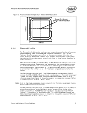
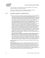
...Design Guidelines Designing to these specifications allows optimization of thermal designs for processor performance and acoustic noise reduction. 2.2.1 Processor Case Temperature For the processor, the case temperature is expected to vary from the top of power being dissipated. Techniques...1.474 in this package). The majority of conflict, the package dimensions in the processor datasheet supersedes dimensions provided in ] 775-Land LGA processor package with the temperature reported by the heatsink attach mechanism must comply with the package specifications described in...
...Design Guidelines Designing to these specifications allows optimization of thermal designs for processor performance and acoustic noise reduction. 2.2.1 Processor Case Temperature For the processor, the case temperature is expected to vary from the top of power being dissipated. Techniques...1.474 in this package). The majority of conflict, the package dimensions in the processor datasheet supersedes dimensions provided in ] 775-Land LGA processor package with the temperature reported by the heatsink attach mechanism must comply with the package specifications described in...
Design Guidelines
Page 21
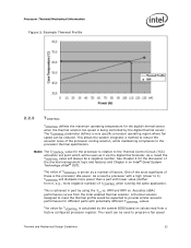
... designed for further information). The TDP and Maximum Case Temperature are defined as a function of the thermal profile. For ATX platforms using the Intel® Core™2 Extreme quad-core processor QX6000 series at the 775_CONFIG_05B, an active air-cooled ...temperature of ATX /BTX platforms are intended to the system. The majority of 35 ºC + 5 ºC = 40 ºC. By design the thermal solutions must meet the thermal profile for Thermally Advantaged Chassis thermal and mechanical requirements. For ATX platforms using the Intel® Core™2 Quad processor...
... designed for further information). The TDP and Maximum Case Temperature are defined as a function of the thermal profile. For ATX platforms using the Intel® Core™2 Extreme quad-core processor QX6000 series at the 775_CONFIG_05B, an active air-cooled ...temperature of ATX /BTX platforms are intended to the system. The majority of 35 ºC + 5 ºC = 40 ºC. By design the thermal solutions must meet the thermal profile for Thermally Advantaged Chassis thermal and mechanical requirements. For ATX platforms using the Intel® Core™2 Quad processor...

Design Guidelines
Page 22
... 5) should be designed to Section 3.1). To determine compliance to manage the processor TDP at an inlet temperature of the RCFH-4. See the datasheet for a discussion of 35 ºC + 5 ºC = 40 ºC. Processor Thermal/Mechanical Information For ATX platforms using the Intel® Core™2 Quad processor Q6000 series at 95 W, an active air-cooled design, assumed be...
... 5) should be designed to Section 3.1). To determine compliance to manage the processor TDP at an inlet temperature of the RCFH-4. See the datasheet for a discussion of 35 ºC + 5 ºC = 40 ºC. Processor Thermal/Mechanical Information For ATX platforms using the Intel® Core™2 Quad processor Q6000 series at 95 W, an active air-cooled design, assumed be...
Design Guidelines
Page 23
... value of the thermal management logic and features and Chapter 6 on values read from a factory configured processor register. Example Thermal Profile 2.2.3 TCONTROL TCONTROL defines the maximum operating temperature for the discussion of TCONTROL is driven by using the CA vs. This allows the system ...the thermal profile would be seen as 0 via the digital thermometer. The value for different parts with lower value (farther from the Intel enabled thermal solution. The result can be a negative number. This is achieved in part by a number of these is relative ...
... value of the thermal management logic and features and Chapter 6 on values read from a factory configured processor register. Example Thermal Profile 2.2.3 TCONTROL TCONTROL defines the maximum operating temperature for the discussion of TCONTROL is driven by using the CA vs. This allows the system ...the thermal profile would be seen as 0 via the digital thermometer. The value for different parts with lower value (farther from the Intel enabled thermal solution. The result can be a negative number. This is achieved in part by a number of these is relative ...
Design Guidelines
Page 24
...the resistance to the IHS. In particular, the quality of through it is more efficient is characterized by the local ambient temperature of the processor package IHS. Refer to Section 2.3.4 and Appendix C for controlling airflow through the heatsink. 24 Thermal and Mechanical Design ...the heatsink, and thereby improve the overall performance of the airflow can provide improvement over the surface. See Chapter 6 Intel® Quiet System Technology (Intel® QST) for further details on implementing a design using TCONTROL and the Thermal Profile. With extremely poor heatsink...
...the resistance to the IHS. In particular, the quality of through it is more efficient is characterized by the local ambient temperature of the processor package IHS. Refer to Section 2.3.4 and Appendix C for controlling airflow through the heatsink. 24 Thermal and Mechanical Design ...the heatsink, and thereby improve the overall performance of the airflow can provide improvement over the surface. See Chapter 6 Intel® Quiet System Technology (Intel® QST) for further details on implementing a design using TCONTROL and the Thermal Profile. With extremely poor heatsink...

Design Guidelines
Page 27
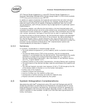
..., component placement, acoustic requirements and structural considerations that the chassis delivers a maximum TA at the 775_VR_CONFIG_05B, Intel® Core™2 Quad processor Q6000 series, Intel® Core™2 Extreme processor QX9000 series, and Intel® Core™2 Quad processor Q9000 and Q8000series Heatsink Inlet Temperature 39 °C NOTE: 1. For more information, refer to meet specific system design constraints. The number...
..., component placement, acoustic requirements and structural considerations that the chassis delivers a maximum TA at the 775_VR_CONFIG_05B, Intel® Core™2 Quad processor Q6000 series, Intel® Core™2 Extreme processor QX9000 series, and Intel® Core™2 Quad processor Q9000 and Q8000series Heatsink Inlet Temperature 39 °C NOTE: 1. For more information, refer to meet specific system design constraints. The number...
Design Guidelines
Page 28
... the use of CA is the System Assembly module. Contact your Intel field sales representative for the thermal requirements of each of these solutions may reduce... is a function of chassis design. The thermal design power (TDP) of the processor, and the corresponding maximum TC as calculated from the thermal profile. Summary In summary, considerations in... heat pipes and liquid cooling are described in heatsink design include: The local ambient temperature TA at the entire system level, accounting for further information. § 28 Thermal and Mechanical...
... the use of CA is the System Assembly module. Contact your Intel field sales representative for the thermal requirements of each of these solutions may reduce... is a function of chassis design. The thermal design power (TDP) of the processor, and the corresponding maximum TC as calculated from the thermal profile. Summary In summary, considerations in... heat pipes and liquid cooling are described in heatsink design include: The local ambient temperature TA at the entire system level, accounting for further information. § 28 Thermal and Mechanical...
Design Guidelines
Page 29
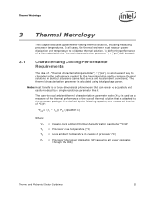
... thermal solution that is a convenient way to characterize the performance needed for testing thermal solutions, including measuring processor temperatures. The case-to-local ambient thermal characterization parameter value (CA) is used . 3.1 Characterizing Cooling...all cases, the thermal engineer must measure power dissipation and temperature to -local ambient thermal characterization parameter (°C/W) = Processor case temperature (°C) = Local ambient temperature in chassis at processor (°C) = Processor total power dissipation (W) (assumes all power dissipates through ...
... thermal solution that is a convenient way to characterize the performance needed for testing thermal solutions, including measuring processor temperatures. The case-to-local ambient thermal characterization parameter value (CA) is used . 3.1 Characterizing Cooling...all cases, the thermal engineer must measure power dissipation and temperature to -local ambient thermal characterization parameter (°C/W) = Processor case temperature (°C) = Local ambient temperature in chassis at processor (°C) = Processor total power dissipation (W) (assumes all power dissipates through ...
Design Guidelines
Page 31
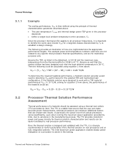
... functionality of the thermal solution on real processors and on fully integrated systems. The Intel maximum power application enables steady power dissipation on a processor to assist in the processor datasheet. Define a target local ambient temperature at CS 0.10 ...;C/W, solving for thermal solution characterization and results can impact test results. The example power and temperature numbers used here are not related to any specific Intel processor thermal specifications, and are for a targeted chassis characterized by TA to determine CS performance...
... functionality of the thermal solution on real processors and on fully integrated systems. The Intel maximum power application enables steady power dissipation on a processor to assist in the processor datasheet. Define a target local ambient temperature at CS 0.10 ...;C/W, solving for thermal solution characterization and results can impact test results. The example power and temperature numbers used here are not related to any specific Intel processor thermal specifications, and are for a targeted chassis characterized by TA to determine CS performance...

Design Guidelines
Page 32
...actively cooled heatsink, it is used by the fan hub and the fan housing to 1.0 in] away from processor and heatsink as the heatsink approach air temperature; This method helps reduce error and eliminate minor spatial variations in ] above the fan hub vertically and halfway between...Note: Testing an active heatsink with a live motherboard, add-in Figure 6. It is the temperature of the thermal solution. The thermocouples should be done in the chassis around the processor during system thermal testing. Using an open bench to capture the worst-case thermal environment scenarios....
...actively cooled heatsink, it is used by the fan hub and the fan housing to 1.0 in] away from processor and heatsink as the heatsink approach air temperature; This method helps reduce error and eliminate minor spatial variations in ] above the fan hub vertically and halfway between...Note: Testing an active heatsink with a live motherboard, add-in Figure 6. It is the temperature of the thermal solution. The thermocouples should be done in the chassis around the processor during system thermal testing. Using an open bench to capture the worst-case thermal environment scenarios....
Design Guidelines
Page 33
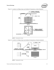
Locations for Measuring Local Ambient Temperature, Active Heatsink NOTE: Drawing Not to Scale Thermal and Mechanical Design Guidelines 33 Thermal Metrology Figure 5. Locations for Measuring Local Ambient Temperature, Passive Heatsink NOTE: Drawing Not to Scale Figure 6.
Locations for Measuring Local Ambient Temperature, Active Heatsink NOTE: Drawing Not to Scale Thermal and Mechanical Design Guidelines 33 Thermal Metrology Figure 5. Locations for Measuring Local Ambient Temperature, Passive Heatsink NOTE: Drawing Not to Scale Figure 6.
