Design Guidelines
Page 2
... provide any license, express or implied, by visiting http://www.intel.com . , The Intel® Core™2 Extreme quad-core processor QX6000 series, Intel® Core™2 Extreme Processor QX9000 series Intel® Core™2 Quad processor Q9000, Q9000S, Q8000, and Q8000S series and Intel® Core™2 Quad processor Q6000 Δ series may make changes to specifications and product descriptions at its discretion to implement these for...
... provide any license, express or implied, by visiting http://www.intel.com . , The Intel® Core™2 Extreme quad-core processor QX6000 series, Intel® Core™2 Extreme Processor QX9000 series Intel® Core™2 Quad processor Q9000, Q9000S, Q8000, and Q8000S series and Intel® Core™2 Quad processor Q6000 Δ series may make changes to specifications and product descriptions at its discretion to implement these for...
Design Guidelines
Page 9
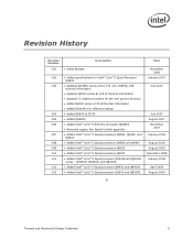
...009 -010 -011 -012 -013 Added specifications for Intel® Core™2 Quad Processor Q6600 Updated QX6800 series at the 775_VR_CONFIG_05B thermal...Intel® Core™2 Extreme processor QX9650 Removed Legacy Fan Speed Control appendix. Added Intel® Core™2 Quad processors Q9550, Q9450, and Q9300 Added Intel® Core™2 Quad processors Q9650 and Q9400 Added Intel® Core™2 Quad processors Q8200 Added Intel® Core™2 Quad processors Q8300 Added Intel® Core™2 Quad processor...
...009 -010 -011 -012 -013 Added specifications for Intel® Core™2 Quad Processor Q6600 Updated QX6800 series at the 775_VR_CONFIG_05B thermal...Intel® Core™2 Extreme processor QX9650 Removed Legacy Fan Speed Control appendix. Added Intel® Core™2 Quad processors Q9550, Q9450, and Q9300 Added Intel® Core™2 Quad processors Q9650 and Q9400 Added Intel® Core™2 Quad processors Q8200 Added Intel® Core™2 Quad processors Q8300 Added Intel® Core™2 Quad processor...
Design Guidelines
Page 11
... are maintained within the system. The result is an increased importance on single processor systems using the Intel® Core™2 Extreme quad-core processor QX6000 series, Intel® Core™2 Quad processor Q6000 series, Intel® Core™2 Quad processor Q9000 and Q8000series, and Intel® Core™2 Extreme processor QX9650. The goal of this document are met for meeting the thermal requirements...
... are maintained within the system. The result is an increased importance on single processor systems using the Intel® Core™2 Extreme quad-core processor QX6000 series, Intel® Core™2 Quad processor Q6000 series, Intel® Core™2 Quad processor Q9000 and Q8000series, and Intel® Core™2 Extreme processor QX9650. The goal of this document are met for meeting the thermal requirements...
Design Guidelines
Page 12
... Intel® Core™2 Extreme processor QX9650 Intel® Core™2 Quad processor Q9000 series at 95 W applies to the Intel® Core™2 Quad processors Q9650, Q9550, Q9505, Q9450, 9400, and Q9300 Intel® Core™2 Quad processor Q8000 series at 95 W applies to the Intel® Core™2 Quad processors Q8200, Q8300, and Q8400 Intel® Core™2 Quad processor Q9000S series at 65 W applies to the Intel® Core™2 Quad processors...
... Intel® Core™2 Extreme processor QX9650 Intel® Core™2 Quad processor Q9000 series at 95 W applies to the Intel® Core™2 Quad processors Q9650, Q9550, Q9505, Q9450, 9400, and Q9300 Intel® Core™2 Quad processor Q8000 series at 95 W applies to the Intel® Core™2 Quad processors Q8200, Q8300, and Q8400 Intel® Core™2 Quad processor Q9000S series at 65 W applies to the Intel® Core™2 Quad processors...
Design Guidelines
Page 13
... Quad-Core processor QX6000 Sequence and Intel® Core™2 Quad Processor Q6000 Sequence Datasheet Intel® Core™2 Extreme Processor QX9000 Series and Intel® Core™2 Quad Processor Q9000, Q9000S, Q8000, and Q8000SSeries Datasheet Intel® Core™2 Duo Processor E8000 and E7000 Series and Intel® Pentium® Dual-Core Processor E5000 Series Thermal and Mechanical Design Guide LGA775 Socket Mechanical Design Guide Fan Specification...
... Quad-Core processor QX6000 Sequence and Intel® Core™2 Quad Processor Q6000 Sequence Datasheet Intel® Core™2 Extreme Processor QX9000 Series and Intel® Core™2 Quad Processor Q9000, Q9000S, Q8000, and Q8000SSeries Datasheet Intel® Core™2 Duo Processor E8000 and E7000 Series and Intel® Pentium® Dual-Core Processor E5000 Series Thermal and Mechanical Design Guide LGA775 Socket Mechanical Design Guide Fan Specification...
Design Guidelines
Page 14
... PWM signal. Fan Speed Control: Thermal solution that results in the value for an active heatsink. The surface mount socket designed to accept the processors in a component specification. The enabled 4 wire fans use with the digital thermal sensor. The ambient air temperature external to a thermal solution through heat spreading. This temperature is...
... PWM signal. Fan Speed Control: Thermal solution that results in the value for an active heatsink. The surface mount socket designed to accept the processors in a component specification. The enabled 4 wire fans use with the digital thermal sensor. The ambient air temperature external to a thermal solution through heat spreading. This temperature is...
Design Guidelines
Page 15
... source must be specified for measurements. Thermal Interface Material: The thermally conductive compound between the heatsink and the processor case. Case-to -ambient thermal characterization parameter. NOTE: Heat source must be specified for measurements. §...be specified for the BTX thermal solution Heatsink temperature measured on the processor that attempts to -ambient thermal characterization parameter (psi). Case-to keep the processor die temperature within factory specifications. A measure of heatsink thermal performance using total package power. TS...
... source must be specified for measurements. Thermal Interface Material: The thermally conductive compound between the heatsink and the processor case. Case-to -ambient thermal characterization parameter. NOTE: Heat source must be specified for measurements. §...be specified for the BTX thermal solution Heatsink temperature measured on the processor that attempts to -ambient thermal characterization parameter (psi). Case-to keep the processor die temperature within factory specifications. A measure of heatsink thermal performance using total package power. TS...
Design Guidelines
Page 17
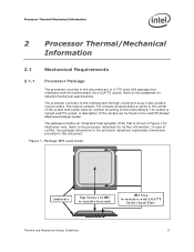
.../Mechanical Information 2.1 Mechanical Requirements 2.1.1 Processor Package The processors covered in the document are in Figure 1 for illustration only. Refer to the datasheet for further information. The package includes an integrated heat spreader (IHS) ... to the motherboard. In case of the socket can be found in the center of IHS to install a heatsink IHS Step to the processor datasheet for detailed mechanical specifications. The socket is shown in a 775-Land LGA package that is named LGA775 socket. The socket contains 775 contacts arrayed about a cavity in...
.../Mechanical Information 2.1 Mechanical Requirements 2.1.1 Processor Package The processors covered in the document are in Figure 1 for illustration only. Refer to the datasheet for further information. The package includes an integrated heat spreader (IHS) ... to the motherboard. In case of the socket can be found in the center of IHS to install a heatsink IHS Step to the processor datasheet for detailed mechanical specifications. The socket is shown in a 775-Land LGA package that is named LGA775 socket. The socket contains 775 contacts arrayed about a cavity in...
Design Guidelines
Page 18
... between the heatsink base and the IHS, it should not exceed the corresponding specification given in the processor datasheet. When a compressive static load is necessary to the processor datasheet specification. The total combination of 2 results in LGA775 Socket Mechanical Design Guide. No...plane of the package is flush with an amplification factor of dynamic and static compressive load should not exceed the processor datasheet compressive dynamic load specification during a mechanical shock event. This allows more uniform and spread over a larger surface area (not the entire...
... between the heatsink base and the IHS, it should not exceed the corresponding specification given in the processor datasheet. When a compressive static load is necessary to the processor datasheet specification. The total combination of 2 results in LGA775 Socket Mechanical Design Guide. No...plane of the package is flush with an amplification factor of dynamic and static compressive load should not exceed the processor datasheet compressive dynamic load specification during a mechanical shock event. This allows more uniform and spread over a larger surface area (not the entire...

Design Guidelines
Page 20
...during installation and actuation to avoid scratching the motherboard. 2.2 Thermal Requirements Refer to the datasheet for the processor thermal specifications. This data is assumed to be installed after reflow, given in the LGA775 Socket Mechanical Design Guide with...13 in x 1.13 in Section 3.4. Designing to these specifications allows optimization of thermal designs for processor performance and acoustic noise reduction. 2.2.1 Processor Case Temperature For the processor, the case temperature is a specification used in place under mechanical shock and vibration events and...
...during installation and actuation to avoid scratching the motherboard. 2.2 Thermal Requirements Refer to the datasheet for the processor thermal specifications. This data is assumed to be installed after reflow, given in the LGA775 Socket Mechanical Design Guide with...13 in x 1.13 in Section 3.4. Designing to these specifications allows optimization of thermal designs for processor performance and acoustic noise reduction. 2.2.1 Processor Case Temperature For the processor, the case temperature is a specification used in place under mechanical shock and vibration events and...
Design Guidelines
Page 23
... specification. Note: The TCONTROL value for TCONTROL is driven by a number of these is achieved in part by the system BIOS based on Intel® Quiet System Technology (Intel® QST). The value for the processor is being controlled by the digital thermal sensor. The ... TCONTROL will always be seen as 0 via the digital thermometer. As a result a processor with lower value (farther from the Intel enabled thermal solution. The TCONTROL parameter defines a very specific processor operating region where fan speed can be expected to reduce the acoustic noise of the thermal ...
... specification. Note: The TCONTROL value for TCONTROL is driven by a number of these is achieved in part by the system BIOS based on Intel® Quiet System Technology (Intel® QST). The value for the processor is being controlled by the digital thermal sensor. The ... TCONTROL will always be seen as 0 via the digital thermometer. As a result a processor with lower value (farther from the Intel enabled thermal solution. The TCONTROL parameter defines a very specific processor operating region where fan speed can be expected to reduce the acoustic noise of the thermal ...

Design Guidelines
Page 25
...Specification V1.2 found at http://www.formfactors.org/. The height of the heatsink must take into consideration the package and socket load limits, the heatsink attach mechanical capabilities, and the mechanical shock and vibration profile targets. Beyond a certain heatsink mass, the cost of developing and implementing a heatsink attach mechanism that use Intel... v1.0 found at http://www.formfactors.org/. This mass includes the fan and the heatsink only. Processor Thermal/Mechanical Information 2.3.1 2.3.2 Heatsink Size The size of the heatsink is generally not entirely available for...
...Specification V1.2 found at http://www.formfactors.org/. The height of the heatsink must take into consideration the package and socket load limits, the heatsink attach mechanical capabilities, and the mechanical shock and vibration profile targets. Beyond a certain heatsink mass, the cost of developing and implementing a heatsink attach mechanism that use Intel... v1.0 found at http://www.formfactors.org/. This mass includes the fan and the heatsink only. Processor Thermal/Mechanical Information 2.3.1 2.3.2 Heatsink Size The size of the heatsink is generally not entirely available for...

Design Guidelines
Page 27
...a maximum TA at the 775_VR_CONFIG_05B, Intel® Core™2 Quad processor Q6000 series, Intel® Core™2 Extreme processor QX9000 series, and Intel® Core™2 Quad processor Q9000 and Q8000series Heatsink Inlet Temperature 39 °C NOTE: 1. Boxed Processor thermal solutions for ATX assume the use...°C 39 °C 35.5 °C NOTE: 1. 2. The following tables show the TA requirements for Intel® Core™2 Extreme quad-core processor QX6000 series at the inlet of system airflow can be used in the chassis where expected the temperature rise is ...
...a maximum TA at the 775_VR_CONFIG_05B, Intel® Core™2 Quad processor Q6000 series, Intel® Core™2 Extreme processor QX9000 series, and Intel® Core™2 Quad processor Q9000 and Q8000series Heatsink Inlet Temperature 39 °C NOTE: 1. Boxed Processor thermal solutions for ATX assume the use...°C 39 °C 35.5 °C NOTE: 1. 2. The following tables show the TA requirements for Intel® Core™2 Extreme quad-core processor QX6000 series at the inlet of system airflow can be used in the chassis where expected the temperature rise is ...
Design Guidelines
Page 31
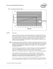
.... TA) / TDP = (67 - 38) / 100 = 0.29 °C/W To determine the required heatsink performance, a heatsink solution provider would need to any specific Intel processor thermal specifications, and are not related to determine CS performance for equation 2 from the thermal profile for illustrative purposes only. If the heatsink solution were designed ...
.... TA) / TDP = (67 - 38) / 100 = 0.29 °C/W To determine the required heatsink performance, a heatsink solution provider would need to any specific Intel processor thermal specifications, and are not related to determine CS performance for equation 2 from the thermal profile for illustrative purposes only. If the heatsink solution were designed ...
Design Guidelines
Page 34
...the IHS. This procedure takes into account the specific features of the 775-Land LGA package and of the LGA775 socket for TC measurement. 3.4 Thermal Metrology Processor Case Temperature Measurement Guidelines To ensure functionality and reliability, the processor is specified for proper operation when TC is... the heatsink base. Before any temperature measurements are often used to measure TC. When measuring the temperature of a 775-Land LGA processor package for TC is required when measuring TC to the IHS of a surface that is intended. § 34 Thermal and Mechanical...
...the IHS. This procedure takes into account the specific features of the 775-Land LGA package and of the LGA775 socket for TC measurement. 3.4 Thermal Metrology Processor Case Temperature Measurement Guidelines To ensure functionality and reliability, the processor is specified for proper operation when TC is... the heatsink base. Before any temperature measurements are often used to measure TC. When measuring the temperature of a 775-Land LGA processor package for TC is required when measuring TC to the IHS of a surface that is intended. § 34 Thermal and Mechanical...
Design Guidelines
Page 36
... Design Guidelines Figure 7 illustrates the relationship between the internal processor clocks and PROCHOT#. While PROCHOT# is fixed for both cores. As an output, PROCHOT# will activate the TCC for a particular processor. This indicates the TCC has been activated. Performance counter registers, status bits in model specific registers (MSRs), and the PROCHOT# output pin are...
... Design Guidelines Figure 7 illustrates the relationship between the internal processor clocks and PROCHOT#. While PROCHOT# is fixed for both cores. As an output, PROCHOT# will activate the TCC for a particular processor. This indicates the TCC has been activated. Performance counter registers, status bits in model specific registers (MSRs), and the PROCHOT# output pin are...

Design Guidelines
Page 37
...of the processor, providing a temperature reduction. When the TCC is engaged, the processor will be activated. The processor continues to the new frequency. Thermal and Mechanical Design Guidelines 37 A processor enabled for the processor. Edge-triggered interrupts will transition to the new core operating voltage... of both a lower operating frequency and voltage. TM2 provides an efficient means of a specific operating frequency and voltage. During the frequency transition, the processor is blocked. Thermal Management Logic and Thermal Monitor Feature Figure 7.
...of the processor, providing a temperature reduction. When the TCC is engaged, the processor will be activated. The processor continues to the new frequency. Thermal and Mechanical Design Guidelines 37 A processor enabled for the processor. Edge-triggered interrupts will transition to the new core operating voltage... of both a lower operating frequency and voltage. TM2 provides an efficient means of a specific operating frequency and voltage. During the frequency transition, the processor is blocked. Thermal Management Logic and Thermal Monitor Feature Figure 7.
Design Guidelines
Page 38
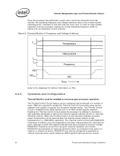
... PROCHOT# transitions around the trip point. Operation and Configuration Thermal Monitor must be configured and monitored in an MSR (model specific register). The Thermal Control Circuit feature can be enabled to maintain a safe operating temperature without the need for further information ...be configured to the datasheet for special software drivers or interrupt handling routines. When the Thermal Control Circuit has been enabled, processor power consumption will occur first, in order to the normal system operating point. Thermal Monitor 2 Frequency and Voltage Ordering TTM2 ...
... PROCHOT# transitions around the trip point. Operation and Configuration Thermal Monitor must be configured and monitored in an MSR (model specific register). The Thermal Control Circuit feature can be enabled to maintain a safe operating temperature without the need for further information ...be configured to the datasheet for special software drivers or interrupt handling routines. When the Thermal Control Circuit has been enabled, processor power consumption will occur first, in order to the normal system operating point. Thermal Monitor 2 Frequency and Voltage Ordering TTM2 ...
Design Guidelines
Page 39
...purposes, the thermal control circuit may be set based on . When using an "on measurements of a well designed processor thermal solution. Similarly, for a duty cycle of 7/8 (87.5%), the clock on time would be activated manually using... Monitor 2 4.2.5 System Considerations Intel requires the Thermal Monitor and Thermal Control Circuit to as frequency increases. Activating the thermal control circuit may also be extended to 87.5%. The processor TDP is selected, the clock...term thermal excursions that does not meet the thermal profile specification published in the ACPI MSRs.
...purposes, the thermal control circuit may be set based on . When using an "on measurements of a well designed processor thermal solution. Similarly, for a duty cycle of 7/8 (87.5%), the clock on time would be activated manually using... Monitor 2 4.2.5 System Considerations Intel requires the Thermal Monitor and Thermal Control Circuit to as frequency increases. Activating the thermal control circuit may also be extended to 87.5%. The processor TDP is selected, the clock...term thermal excursions that does not meet the thermal profile specification published in the ACPI MSRs.
Design Guidelines
Page 40
..., the Thermal Monitor feature must be capable of reducing the processor power and temperature and the processor could shutdown and signal THERMTRIP#. 4.2.6 4.2.7 4.2.8 Thermal Management Logic and Thermal Monitor Feature control circuit to activate under designed, there is a risk that do not meet these specifications could be subject to use the PROCHOT# signal as...
..., the Thermal Monitor feature must be capable of reducing the processor power and temperature and the processor could shutdown and signal THERMTRIP#. 4.2.6 4.2.7 4.2.8 Thermal Management Logic and Thermal Monitor Feature control circuit to activate under designed, there is a risk that do not meet these specifications could be subject to use the PROCHOT# signal as...
