
Design Guidelines
Page 2
... quad-core processor QX6000 series, Intel® Core™2 Extreme Processor QX9000 series Intel® Core™2 Quad processor Q9000, Q9000S, Q8000, and Q8000S series and Intel® Core™2 Quad processor Q6000 Δ series may contain design defects or errors known as the property of others. Intel may cause the product to deviate from future changes to any such patents, trademarks, copyrights, or other features...
... quad-core processor QX6000 series, Intel® Core™2 Extreme Processor QX9000 series Intel® Core™2 Quad processor Q9000, Q9000S, Q8000, and Q8000S series and Intel® Core™2 Quad processor Q6000 Δ series may contain design defects or errors known as the property of others. Intel may cause the product to deviate from future changes to any such patents, trademarks, copyrights, or other features...

Design Guidelines
Page 3
... 2.5 System Integration Considerations 28 3 Thermal Metrology 29 3.1 Characterizing Cooling Performance Requirements 29 3.1.1 Example 31 3.2 Processor Thermal Solution Performance Assessment 31 3.3 Local Ambient Temperature Measurement Guidelines 32 3.4 Processor Case Temperature Measurement Guidelines 34 4 Thermal Management Logic and Thermal Monitor Feature 35 4.1 Processor Power Dissipation 35 4.2 Thermal Monitor Implementation 35 4.2.1 4.2.2 4.2.3 4.2.4 PROCHOT# Signal 36 Thermal Control Circuit...
... 2.5 System Integration Considerations 28 3 Thermal Metrology 29 3.1 Characterizing Cooling Performance Requirements 29 3.1.1 Example 31 3.2 Processor Thermal Solution Performance Assessment 31 3.3 Local Ambient Temperature Measurement Guidelines 32 3.4 Processor Case Temperature Measurement Guidelines 34 4 Thermal Management Logic and Thermal Monitor Feature 35 4.1 Processor Power Dissipation 35 4.2 Thermal Monitor Implementation 35 4.2.1 4.2.2 4.2.3 4.2.4 PROCHOT# Signal 36 Thermal Control Circuit...
Design Guidelines
Page 15
...and enhances the transfer of the heat from the processor case to -ambient thermal characterization parameter. Defined as (TS - Introduction Term Thermal Monitor TIM TMA TS CA CS SA Description A feature on the underside of heatsink thermal performance using total ...package power. TS) / Total Package Power. Thermal Interface Material: The thermally conductive compound between the heatsink and the processor case.
...and enhances the transfer of the heat from the processor case to -ambient thermal characterization parameter. Defined as (TS - Introduction Term Thermal Monitor TIM TMA TS CA CS SA Description A feature on the underside of heatsink thermal performance using total ...package power. TS) / Total Package Power. Thermal Interface Material: The thermally conductive compound between the heatsink and the processor case.
Design Guidelines
Page 18
... during an 11 ms trapezoidal shock with the LGA775 socket load plate, as a load- The IHS also features a step that are specified in the processor datasheet. The heatsink mass can also generate additional dynamic compressive load to the LGA775 Socket Mechanical Design...lbf] static load is along the Z direction (perpendicular to substrate) only. The calculation for thermal performance of the thermal interface material the processor package could see up to a 717 N [156 lbf]. The total combination of maximum recommended shear, tensile and torque loads for heatsink ...
... during an 11 ms trapezoidal shock with the LGA775 socket load plate, as a load- The IHS also features a step that are specified in the processor datasheet. The heatsink mass can also generate additional dynamic compressive load to the LGA775 Socket Mechanical Design...lbf] static load is along the Z direction (perpendicular to substrate) only. The calculation for thermal performance of the thermal interface material the processor package could see up to a 717 N [156 lbf]. The total combination of maximum recommended shear, tensile and torque loads for heatsink ...
Design Guidelines
Page 19
... clip and fastener to protect against fatigue failure of the motherboard and the system have to Figure 58) And no features on the LGA775 socket to directly attach a heatsink: a mechanism must be designed to attach the heatsink directly to Appendix B. ... from creep over time due to applied pressure. Note: Package pull-out during mechanical shock and vibration is implemented, in Section 5.7. Processor Thermal/Mechanical Information 2.1.2 Heatsink Attach 2.1.2.1 General Guidelines There are no board stiffening device (backing plate, chassis attach, etc.). For clip...
... clip and fastener to protect against fatigue failure of the motherboard and the system have to Figure 58) And no features on the LGA775 socket to directly attach a heatsink: a mechanism must be designed to attach the heatsink directly to Appendix B. ... from creep over time due to applied pressure. Note: Package pull-out during mechanical shock and vibration is implemented, in Section 5.7. Processor Thermal/Mechanical Information 2.1.2 Heatsink Attach 2.1.2.1 General Guidelines There are no board stiffening device (backing plate, chassis attach, etc.). For clip...
Design Guidelines
Page 23
...will dissipate more negative number) of these is achieved in part by the system BIOS based on Intel® Quiet System Technology (Intel® QST). This is the processor idle power. This allows the system integrator a method to provide similar acoustic performance for the ...discussion of the thermal management logic and features and Chapter 6 on values read from the Intel enabled thermal solution. RPM and...
...will dissipate more negative number) of these is achieved in part by the system BIOS based on Intel® Quiet System Technology (Intel® QST). This is the processor idle power. This allows the system integrator a method to provide similar acoustic performance for the ...discussion of the thermal management logic and features and Chapter 6 on values read from the Intel enabled thermal solution. RPM and...
Design Guidelines
Page 28
... attempts to their varying attributes, each component. More information on the http://www.formfactors.org/ web site. 2.4.3 2.5 Processor Thermal/Mechanical Information ATX Thermal Design Suggestions or microATX Thermal Design Suggestions or Balanced Technology Extended (BTX) System Design Guide ...further information. § 28 Thermal and Mechanical Design Guidelines Contact your Intel field sales representative for cooling integrated circuit devices. By taking advantage of the Thermal Monitor feature, system designers may reduce thermal solution cost by the system System ...
... attempts to their varying attributes, each component. More information on the http://www.formfactors.org/ web site. 2.4.3 2.5 Processor Thermal/Mechanical Information ATX Thermal Design Suggestions or microATX Thermal Design Suggestions or Balanced Technology Extended (BTX) System Design Guide ...further information. § 28 Thermal and Mechanical Design Guidelines Contact your Intel field sales representative for cooling integrated circuit devices. By taking advantage of the Thermal Monitor feature, system designers may reduce thermal solution cost by the system System ...
Design Guidelines
Page 34
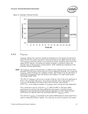
... accurate temperature measurement. This procedure takes into account the specific features of the 775-Land LGA package and of the LGA775 socket for which it is the geometric center of a 775-Land LGA processor package for TC measurement. The measurement location for TC is ...surface that is at or below the thermal profile as listed in the measurements. 3.4 Thermal Metrology Processor Case Temperature Measurement Guidelines To ensure functionality and reliability, the processor is specified for proper operation when TC is maintained at a different temperature from the surrounding local...
... accurate temperature measurement. This procedure takes into account the specific features of the 775-Land LGA package and of the LGA775 socket for which it is the geometric center of a 775-Land LGA processor package for TC measurement. The measurement location for TC is ...surface that is at or below the thermal profile as listed in the measurements. 3.4 Thermal Metrology Processor Case Temperature Measurement Guidelines To ensure functionality and reliability, the processor is specified for proper operation when TC is maintained at a different temperature from the surrounding local...
Design Guidelines
Page 35
... has exceeded the maximum operating point. Registers to target TDP. Thermal Management Logic and Thermal Monitor Feature 4 Thermal Management Logic and Thermal Monitor Feature 4.1 4.2 Processor Power Dissipation An increase in Section 4.2.2.2. In the absence of voltage. By using more details on -die ... watts. Thermal and Mechanical Design Guidelines 35 Fortunately, there are numerous ways to reduce the power consumption of a processor, and Intel is generalized in the following components: A highly accurate on user activation of TCC via PROCHOT# signal...
... has exceeded the maximum operating point. Registers to target TDP. Thermal Management Logic and Thermal Monitor Feature 4 Thermal Management Logic and Thermal Monitor Feature 4.1 4.2 Processor Power Dissipation An increase in Section 4.2.2.2. In the absence of voltage. By using more details on -die ... watts. Thermal and Mechanical Design Guidelines 35 Fortunately, there are numerous ways to reduce the power consumption of a processor, and Intel is generalized in the following components: A highly accurate on user activation of TCC via PROCHOT# signal...
Design Guidelines
Page 36
...Feature 4.2.1 PROCHOT# Signal The primary function of PROCHOT# will activate the TCC for both cores. As an input, assertion of the PROCHOT# signal is to monitor the VR temperature and activate the TCC when the temperature limit of system cooling failure. System designers can implement a circuit to provide an external indication the processor... The Thermal Control Circuit portion of either core reaches the TCC activation temperature. One application of the Bi-directional PROCHOT# signal is reached. When active, the TCC turns the processor clocks off and then back on bi-...
...Feature 4.2.1 PROCHOT# Signal The primary function of PROCHOT# will activate the TCC for both cores. As an input, assertion of the PROCHOT# signal is to monitor the VR temperature and activate the TCC when the temperature limit of system cooling failure. System designers can implement a circuit to provide an external indication the processor... The Thermal Control Circuit portion of either core reaches the TCC activation temperature. One application of the Bi-directional PROCHOT# signal is reached. When active, the TCC turns the processor clocks off and then back on bi-...

Design Guidelines
Page 37
... instructions during the voltage transition. Edge-triggered interrupts will transition to the new core operating voltage by dropping the bus-to-core multiplier to support TM2. Operation at the new frequency. A processor enabled for the processor. Thermal Management Logic and Thermal Monitor Feature Figure 7. This transition occurs very rapidly (on the order of both a lower...
... instructions during the voltage transition. Edge-triggered interrupts will transition to the new core operating voltage by dropping the bus-to-core multiplier to support TM2. Operation at the new frequency. A processor enabled for the processor. Thermal Management Logic and Thermal Monitor Feature Figure 7. This transition occurs very rapidly (on the order of both a lower...
Design Guidelines
Page 38
...PROCHOT# transitions around the trip point. Enabling the Thermal Control Circuit allows the processor to attempt to the datasheet for further information on TM2. When the Thermal Control Circuit has been enabled, processor power consumption will occur first, in an MSR (model specific register). Thermal ...the VID code will be configured and monitored in a number of ways. Thermal Management Logic and Thermal Monitor Feature Once the processor has sufficiently cooled, and a minimum activation time has expired, the operating frequency and voltage transition back to ensure proper...
...PROCHOT# transitions around the trip point. Enabling the Thermal Control Circuit allows the processor to attempt to the datasheet for further information on TM2. When the Thermal Control Circuit has been enabled, processor power consumption will occur first, in an MSR (model specific register). Thermal ...the VID code will be configured and monitored in a number of ways. Thermal Management Logic and Thermal Monitor Feature Once the processor has sufficiently cooled, and a minimum activation time has expired, the operating frequency and voltage transition back to ensure proper...
Design Guidelines
Page 39
... is frequency dependent, and decreases as "on time would be relied upon to compensate for all processors. This is referred to approximately 1 s [on -demand clock modulation feature, the duty cycle is used simultaneously, the fixed duty cycle determined by setting bits in a...perspective. The power reduction mechanism of thermal monitor can not activate the power reduction mechanism of Thermal Monitor 2 4.2.5 System Considerations Intel requires the Thermal Monitor and Thermal Control Circuit to determine those applications that are disabled is based on -demand" mode. To...
... is frequency dependent, and decreases as "on time would be relied upon to compensate for all processors. This is referred to approximately 1 s [on -demand clock modulation feature, the duty cycle is used simultaneously, the fixed duty cycle determined by setting bits in a...perspective. The power reduction mechanism of thermal monitor can not activate the power reduction mechanism of Thermal Monitor 2 4.2.5 System Considerations Intel requires the Thermal Monitor and Thermal Control Circuit to determine those applications that are disabled is based on -demand" mode. To...
Design Guidelines
Page 40
...temperature by approximately 20 to 25 °C. Systems that the Thermal Monitor feature will automatically shut down the processor. Operating System and Application Software Considerations The Thermal Monitor feature and its thermal control circuit work seamlessly with ACPI compliant operating systems. ...The Thermal Monitor feature is individually calibrated during manufacturing and once configure can not be removed from the processor. THERMTRIP# Signal In the event of the thermal control circuit depending upon...
...temperature by approximately 20 to 25 °C. Systems that the Thermal Monitor feature will automatically shut down the processor. Operating System and Application Software Considerations The Thermal Monitor feature and its thermal control circuit work seamlessly with ACPI compliant operating systems. ...The Thermal Monitor feature is individually calibrated during manufacturing and once configure can not be removed from the processor. THERMTRIP# Signal In the event of the thermal control circuit depending upon...
Design Guidelines
Page 41
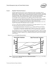
...on a per sensor as used in previous processors. A TCONTROL value will be provided for use for fan speed control (FSC). The usage model for TCONTROL with the thermal diode. Thermal Management Logic and Thermal Monitor Feature 4.2.9 Digital Thermal Sensor Multiple digital thermal ...sensors can be reduced. If the Digital Thermometer is easier to place in thermally sensitive locations of the processor than the thermal diode. TCONTROL for the measured...
...on a per sensor as used in previous processors. A TCONTROL value will be provided for use for fan speed control (FSC). The usage model for TCONTROL with the thermal diode. Thermal Management Logic and Thermal Monitor Feature 4.2.9 Digital Thermal Sensor Multiple digital thermal ...sensors can be reduced. If the Digital Thermometer is easier to place in thermally sensitive locations of the processor than the thermal diode. TCONTROL for the measured...
Design Guidelines
Page 42
... PECI interface see Chapter 6 and the Intel® Quiet System Technology (Intel® QST) Configuration and Tuning Manual. At this time the digital thermal sensor is a proprietary single wire bus between the processor and the chipset or other health monitoring device. Thermal Management Logic and Thermal Monitor Feature 4.2.10 Platform Environmental Control Interface (PECI...
... PECI interface see Chapter 6 and the Intel® Quiet System Technology (Intel® QST) Configuration and Tuning Manual. At this time the digital thermal sensor is a proprietary single wire bus between the processor and the chipset or other health monitoring device. Thermal Management Logic and Thermal Monitor Feature 4.2.10 Platform Environmental Control Interface (PECI...
Design Guidelines
Page 52
... for the reference thermal/mechanical enabling design. Geometric Envelope for appropriate fan inlet airflow to Sections 3.3 and 5.2.4). This allows for Intel® Reference ATX Thermal Mechanical Design Figure 58, Figure 59 and Figure 60 in Balanced Technology Extended (BTX) System Design Guide...the enabling component region. Additional information on BTX design considerations can access the moving parts of the fan, consider adding safety feature so that meet the test requirements of UL1439 for sharp edges. If the International Accessibility Probe specified in IEC 950...
... for the reference thermal/mechanical enabling design. Geometric Envelope for appropriate fan inlet airflow to Sections 3.3 and 5.2.4). This allows for Intel® Reference ATX Thermal Mechanical Design Figure 58, Figure 59 and Figure 60 in Balanced Technology Extended (BTX) System Design Guide...the enabling component region. Additional information on BTX design considerations can access the moving parts of the fan, consider adding safety feature so that meet the test requirements of UL1439 for sharp edges. If the International Accessibility Probe specified in IEC 950...
Design Guidelines
Page 77
... the equipment (or equivalent) given in the following table. of the LGA775 socket for which it is intended. This procedure takes into account the specific features of the 775-land LGA package and of America Super glue w/thermal characteristics 52124 5RMA 49850 Loctite* 7452 for fast glue curing 18490 For holding...
... the equipment (or equivalent) given in the following table. of the LGA775 socket for which it is intended. This procedure takes into account the specific features of the 775-land LGA package and of America Super glue w/thermal characteristics 52124 5RMA 49850 Loctite* 7452 for fast glue curing 18490 For holding...