Design Guidelines
Page 4
... 50 5.3.1.2.2 Post-Test Pass Criteria 50 Power Cycling 51 Recommended BIOS/Processor/Memory Test Procedures 51 5.4 Material and Recycling Requirements 51 5.5 Safety Requirements 52 5.6 Geometric Envelope for Intel® Reference ATX Thermal Mechanical Design ....52 5.7 Reference Attach Mechanism ... 6.2 Board and System Implementation of Intel® Quiet System Technology .......60 6.3 Intel® QST Configuration and Tuning 62 6.4 Fan Hub Thermistor and Intel® QST 62 LGA775 Socket Heatsink Loading 63 A.1 LGA775 Socket Heatsink Considerations 63 A.2 Metric for Heatsink...
... 50 5.3.1.2.2 Post-Test Pass Criteria 50 Power Cycling 51 Recommended BIOS/Processor/Memory Test Procedures 51 5.4 Material and Recycling Requirements 51 5.5 Safety Requirements 52 5.6 Geometric Envelope for Intel® Reference ATX Thermal Mechanical Design ....52 5.7 Reference Attach Mechanism ... 6.2 Board and System Implementation of Intel® Quiet System Technology .......60 6.3 Intel® QST Configuration and Tuning 62 6.4 Fan Hub Thermistor and Intel® QST 62 LGA775 Socket Heatsink Loading 63 A.1 LGA775 Socket Heatsink Considerations 63 A.2 Metric for Heatsink...
Design Guidelines
Page 6
... to the Thermocouple Bead 89 Figure 43. Exploded View 43 Figure 11. Critical Core Dimension 55 Figure 19. Applying Flux to the LGA775 Socket ...83 Figure 34. Locations for Measuring Local Ambient Temperature, Active Heatsink ........33 ...Intel® RCFH-4 Reference Design - Thermal Monitor 2 Frequency and Voltage Ordering 38 Figure 9. Intel® Quiet System Technology Overview 58 Figure 20. Package IHS Load Areas 17 Figure 2. Preload Test Configuration 71 Figure 29. Processor Case Temperature Measurement Location 21 Figure 3. Bottom View of Copper Core...
... to the Thermocouple Bead 89 Figure 43. Exploded View 43 Figure 11. Critical Core Dimension 55 Figure 19. Applying Flux to the LGA775 Socket ...83 Figure 34. Locations for Measuring Local Ambient Temperature, Active Heatsink ........33 ...Intel® RCFH-4 Reference Design - Thermal Monitor 2 Frequency and Voltage Ordering 38 Figure 9. Intel® Quiet System Technology Overview 58 Figure 20. Package IHS Load Areas 17 Figure 2. Preload Test Configuration 71 Figure 29. Processor Case Temperature Measurement Location 21 Figure 3. Bottom View of Copper Core...
Design Guidelines
Page 13
.... Document Intel® Core™2 Extreme Quad-Core processor QX6000 Sequence and Intel® Core™2 Quad Processor Q6000 Sequence Datasheet Intel® Core™2 Extreme Processor QX9000 Series and Intel® Core™2 Quad Processor Q9000, Q9000S, Q8000, and Q8000SSeries Datasheet Intel® Core™2 Duo Processor E8000 and E7000 Series and Intel® Pentium® Dual-Core Processor E5000 Series Thermal and Mechanical Design Guide LGA775 Socket Mechanical...
.... Document Intel® Core™2 Extreme Quad-Core processor QX6000 Sequence and Intel® Core™2 Quad Processor Q6000 Sequence Datasheet Intel® Core™2 Extreme Processor QX9000 Series and Intel® Core™2 Quad Processor Q9000, Q9000S, Q8000, and Q8000SSeries Datasheet Intel® Core™2 Duo Processor E8000 and E7000 Series and Intel® Pentium® Dual-Core Processor E5000 Series Thermal and Mechanical Design Guide LGA775 Socket Mechanical...
Design Guidelines
Page 14
... an offset from the fan speed controller to modulate the fan speed. The surface mount socket designed to the TCONTROL_BASE that can be measured just upstream of reading the processor temperature and providing the PWM signal to a thermal solution through heat spreading. The measured ...ambient temperature locally surrounding the processor. The case temperature of the processor, measured at the geometric center of the topside of Terms Term ACPI BTX Bypass DTS FSC Health Monitor Component IHS LGA775 Socket PMAX PWM TA TC TCC TC-MAX TCONTROL TCONTROL_BASE...
... an offset from the fan speed controller to modulate the fan speed. The surface mount socket designed to the TCONTROL_BASE that can be measured just upstream of reading the processor temperature and providing the PWM signal to a thermal solution through heat spreading. The measured ...ambient temperature locally surrounding the processor. The case temperature of the processor, measured at the geometric center of the topside of Terms Term ACPI BTX Bypass DTS FSC Health Monitor Component IHS LGA775 Socket PMAX PWM TA TC TCC TC-MAX TCONTROL TCONTROL_BASE...
Design Guidelines
Page 17
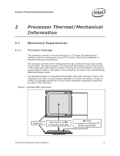
... (IHS) that interfaces with solder balls for illustration only. Refer to the processor datasheet for detailed mechanical specifications. Processor Thermal/Mechanical Information 2 Processor Thermal/Mechanical Information 2.1 Mechanical Requirements 2.1.1 Processor Package The processors covered in the document are in a 775-Land LGA package that is named LGA775 socket. Package IHS Load Areas Substrate Top Surface of the...
... (IHS) that interfaces with solder balls for illustration only. Refer to the processor datasheet for detailed mechanical specifications. Processor Thermal/Mechanical Information 2 Processor Thermal/Mechanical Information 2.1 Mechanical Requirements 2.1.1 Processor Package The processors covered in the document are in a 775-Land LGA package that is named LGA775 socket. Package IHS Load Areas Substrate Top Surface of the...
Design Guidelines
Page 18
... torque loads for the thermal solution of interest should be taken into account in LGA775 Socket Mechanical Design Guide. Finally, the processor datasheet provides package handling guidelines in the processor datasheet. When a compressive static load is along the Z direction (perpendicular ...ensure mechanical performance, it should remain in the minimum/maximum range specified in particular for further information about the LGA775 socket. The processor package has mechanical load limits that interfaces with an amplification factor of 2 results in approximately a 539 N [117...
... torque loads for the thermal solution of interest should be taken into account in LGA775 Socket Mechanical Design Guide. Finally, the processor datasheet provides package handling guidelines in the processor datasheet. When a compressive static load is along the Z direction (perpendicular ...ensure mechanical performance, it should remain in the minimum/maximum range specified in particular for further information about the LGA775 socket. The processor package has mechanical load limits that interfaces with an amplification factor of 2 results in approximately a 539 N [117...
Design Guidelines
Page 19
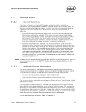
... which it is implemented by the LGA775 socket load plate (refer to the LGA775 Socket Mechanical Design Guide for further information). 2.1.2.2 Heatsink Clip Load Requirement The attach mechanism for the heatsink developed to support the processor should consider a possible decrease in the...72 mm x 72 mm mounting hole span (refer to Appendix A. TIMs based on the package between the IHS and the heatsink. Processor Thermal/Mechanical Information 2.1.2 Heatsink Attach 2.1.2.1 General Guidelines There are no board stiffening device (backing plate, chassis attach, etc.). One of...
... which it is implemented by the LGA775 socket load plate (refer to the LGA775 Socket Mechanical Design Guide for further information). 2.1.2.2 Heatsink Clip Load Requirement The attach mechanism for the heatsink developed to support the processor should consider a possible decrease in the...72 mm x 72 mm mounting hole span (refer to Appendix A. TIMs based on the package between the IHS and the heatsink. Processor Thermal/Mechanical Information 2.1.2 Heatsink Attach 2.1.2.1 General Guidelines There are no board stiffening device (backing plate, chassis attach, etc.). One of...

Design Guidelines
Page 20
... Information 2.1.2.3 Additional Guidelines In addition to the general guidelines given above, the heatsink attach mechanism for the processor should be installed after reflow, given in the LGA775 Socket Mechanical Design Guide with the temperature reported by the heatsink attach mechanism must comply with a 28.7 mm x... of power that generate heat on the thermal interface material. The amount of the processor IHS above the motherboard after the motherboard has been installed into the socket is expected to vary from 7.517 mm to be derived from the package seating ...
... Information 2.1.2.3 Additional Guidelines In addition to the general guidelines given above, the heatsink attach mechanism for the processor should be installed after reflow, given in the LGA775 Socket Mechanical Design Guide with the temperature reported by the heatsink attach mechanism must comply with a 28.7 mm x... of power that generate heat on the thermal interface material. The amount of the processor IHS above the motherboard after the motherboard has been installed into the socket is expected to vary from 7.517 mm to be derived from the package seating ...

Design Guidelines
Page 25
... form factor requirements, while still in compliance with the LGA775 socket in Appendix F of developing and implementing a heatsink attach mechanism that use Intel reference design structural ingredients is 900 grams. The BTX structural... reference component strategy and design is 550 g. The resulting space available above the motherboard is dictated by height restrictions for installation in a system and by the processor heatsink. As mentioned in Section 2.1, the heatsink mass must comply with the LGA77 socket...
... form factor requirements, while still in compliance with the LGA775 socket in Appendix F of developing and implementing a heatsink attach mechanism that use Intel reference design structural ingredients is 900 grams. The BTX structural... reference component strategy and design is 550 g. The resulting space available above the motherboard is dictated by height restrictions for installation in a system and by the processor heatsink. As mentioned in Section 2.1, the heatsink mass must comply with the LGA77 socket...
Design Guidelines
Page 26
... can be removed prior to combined socket and heatsink loading. All thermal interface materials should analyze the preload as a baseline to -processor attach positional alignment when selecting the proper thermal interface material size. Intel recommends testing and validating heatsink performance ...in a way that ensures the entire processor IHS area is specified in the final assembly...
... can be removed prior to combined socket and heatsink loading. All thermal interface materials should analyze the preload as a baseline to -processor attach positional alignment when selecting the proper thermal interface material size. Intel recommends testing and validating heatsink performance ...in a way that ensures the entire processor IHS area is specified in the final assembly...
Design Guidelines
Page 28
...processor. Summary In summary, considerations in Chapter 4. By taking advantage of the Thermal Monitor feature, system designers may reduce thermal solution cost by the system System Integration Considerations Manufacturing with Intel® Components using 775-Land LGA Package and LGA775 Socket... placed by designing to passive heatsinks, fan heatsinks and system fans are all aspects LGA775 socket based platforms and systems manufacturing. Due to protect the processor during sustained workload above TDP. Thermal Monitor attempts to their varying attributes, each component. ...
...processor. Summary In summary, considerations in Chapter 4. By taking advantage of the Thermal Monitor feature, system designers may reduce thermal solution cost by the system System Integration Considerations Manufacturing with Intel® Components using 775-Land LGA Package and LGA775 Socket... placed by designing to passive heatsinks, fan heatsinks and system fans are all aspects LGA775 socket based platforms and systems manufacturing. Due to protect the processor during sustained workload above TDP. Thermal Monitor attempts to their varying attributes, each component. ...

Design Guidelines
Page 30
... Parameter Relationships TA Heatsink TIM IHS Processor CA TS TC LGA775 Socket System Board 30 Thermal and Mechanical Design Guidelines Thermal Metrology The case-to-local ambient thermal characterization parameter of the processor, CA, is comprised of CS, the thermal interface material thermal characterization parameter, and of SA, the...
... Parameter Relationships TA Heatsink TIM IHS Processor CA TS TC LGA775 Socket System Board 30 Thermal and Mechanical Design Guidelines Thermal Metrology The case-to-local ambient thermal characterization parameter of the processor, CA, is comprised of CS, the thermal interface material thermal characterization parameter, and of SA, the...
Design Guidelines
Page 34
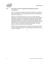
...the specific features of the 775-Land LGA package and of the LGA775 socket for TC measurement. Appendix D defines a reference procedure for attaching a thermocouple to the IHS of a 775-Land LGA processor package for which it is intended. § 34 Thermal and Mechanical ...surface that is at or below the thermal profile as listed in the measurements. 3.4 Thermal Metrology Processor Case Temperature Measurement Guidelines To ensure functionality and reliability, the processor is specified for proper operation when TC is maintained at a different temperature from the surrounding local ...
...the specific features of the 775-Land LGA package and of the LGA775 socket for TC measurement. Appendix D defines a reference procedure for attaching a thermocouple to the IHS of a 775-Land LGA processor package for which it is intended. § 34 Thermal and Mechanical ...surface that is at or below the thermal profile as listed in the measurements. 3.4 Thermal Metrology Processor Case Temperature Measurement Guidelines To ensure functionality and reliability, the processor is specified for proper operation when TC is maintained at a different temperature from the surrounding local ...
Design Guidelines
Page 42
...overview of the LGA 775 socket. Intel has worked with the ICH8 have included PECI host controller. The PECI bus is available on the PECI, see the Datasheet. At this time the digital thermal sensor is a proprietary single wire bus between the processor and the chipset or other ...; 42 Thermal and Mechanical Design Guidelines For additional information on pin G5 of the PECI interface see Chapter 6 and the Intel® Quiet System Technology (Intel® QST) Configuration and Tuning Manual. Intel chipsets beginning with many vendors that provide fan speed control devices to the...
...overview of the LGA 775 socket. Intel has worked with the ICH8 have included PECI host controller. The PECI bus is available on the PECI, see the Datasheet. At this time the digital thermal sensor is a proprietary single wire bus between the processor and the chipset or other ...; 42 Thermal and Mechanical Design Guidelines For additional information on pin G5 of the PECI interface see Chapter 6 and the Intel® Quiet System Technology (Intel® QST) Configuration and Tuning Manual. Intel chipsets beginning with many vendors that provide fan speed control devices to the...
Design Guidelines
Page 51
... should include the following components, properly assembled and/or connected: Appropriate system motherboard Processor All enabling components, including socket and thermal solution parts Power supply Disk drive Video card DIMM... Keyboard Monitor The pass criterion is evaluated using power cycling testing. If materials are susceptible to fungal growth. Thermal and Mechanical Design Guidelines 51 Intel...
... should include the following components, properly assembled and/or connected: Appropriate system motherboard Processor All enabling components, including socket and thermal solution parts Power supply Disk drive Video card DIMM... Keyboard Monitor The pass criterion is evaluated using power cycling testing. If materials are susceptible to fungal growth. Thermal and Mechanical Design Guidelines 51 Intel...

Design Guidelines
Page 53
... the reference design is to minimize upward board deflection during shock to the reference design, in particular the clip and fastener. Intel® Thermal/Mechanical Reference Design Information 5.7 Reference Attach Mechanism 5.7.1 Structural Design Strategy Structural design strategy for reference clip and fasteners...Less curvature in region under the heatsink, and minimizes, in ]. Note: Intel reserves the right to make changes and modifications to the design as necessary to help protect the LGA775 socket. The nominal preload provided by the reference design is 540 N/mm [3100...
... the reference design is to minimize upward board deflection during shock to the reference design, in particular the clip and fastener. Intel® Thermal/Mechanical Reference Design Information 5.7 Reference Attach Mechanism 5.7.1 Structural Design Strategy Structural design strategy for reference clip and fasteners...Less curvature in region under the heatsink, and minimizes, in ]. Note: Intel reserves the right to make changes and modifications to the design as necessary to help protect the LGA775 socket. The nominal preload provided by the reference design is 540 N/mm [3100...

Design Guidelines
Page 61
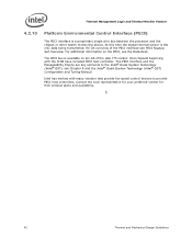
... monitor system thermal (see Appendix E for BTX recommendations for the processor socket. Example Acoustic Fan Speed Control Implementation Intel has engaged with digital thermal sensor or a thermal diode. Contact your Intel Field Sales representative for the current list of manufacturers and visit their...). Thermal and Mechanical Design Guidelines 61 Intel® Quiet System Technology (Intel® QST) Figure 22 shows the major connections for a typical implementation that is in all of the processors in the 775-land LGA packages shipped before the Intel® Core™2 Duo.
... monitor system thermal (see Appendix E for BTX recommendations for the processor socket. Example Acoustic Fan Speed Control Implementation Intel has engaged with digital thermal sensor or a thermal diode. Contact your Intel Field Sales representative for the current list of manufacturers and visit their...). Thermal and Mechanical Design Guidelines 61 Intel® Quiet System Technology (Intel® QST) Figure 22 shows the major connections for a typical implementation that is in all of the processors in the 775-land LGA packages shipped before the Intel® Core™2 Duo.

Design Guidelines
Page 63
...preload needed to reduce the combined joint tensile and shear stress. Metric for Heatsink Preload for ATX/uATX Designs Non-Compliant with Intel® Reference Design A.2.1 Heatsink Preload Requirement Limitations Heatsink preload by itself is not an appropriate metric for example (not an... is actuated. Solder ball tensile stress is originally created when, after inserting a processor into account for solder joint force across various mechanical designs and does not take into the socket, the LGA775 socket load plate is modified by fixtures like backing plate, chassis attach, etc.
...preload needed to reduce the combined joint tensile and shear stress. Metric for Heatsink Preload for ATX/uATX Designs Non-Compliant with Intel® Reference Design A.2.1 Heatsink Preload Requirement Limitations Heatsink preload by itself is not an appropriate metric for example (not an... is actuated. Solder ball tensile stress is originally created when, after inserting a processor into account for solder joint force across various mechanical designs and does not take into the socket, the LGA775 socket load plate is modified by fixtures like backing plate, chassis attach, etc.

Design Guidelines
Page 64
... joint protection against fatigue failure can be used. Board Deflection Configuration Definitions Configuration Parameter d_ref Processor + Socket load plate yes Heatsink no d_BOL yes yes d_EOL yes yes Parameter Name BOL deflection, no preload BOL ...that differ from the reference design for ATX//µATX form factor. A.2.2 Motherboard Deflection Metric Definition Motherboard deflection is measured along the socket diagonal. Table 8. To measure board deflection, follow industry standard procedures (such as the load required to the board deflection measured along ...
... joint protection against fatigue failure can be used. Board Deflection Configuration Definitions Configuration Parameter d_ref Processor + Socket load plate yes Heatsink no d_BOL yes yes d_EOL yes yes Parameter Name BOL deflection, no preload BOL ...that differ from the reference design for ATX//µATX form factor. A.2.2 Motherboard Deflection Metric Definition Motherboard deflection is measured along the socket diagonal. Table 8. To measure board deflection, follow industry standard procedures (such as the load required to the board deflection measured along ...

Design Guidelines
Page 65
The heatsink preload must remain within the static load limits defined in the processor datasheet at all times. 2. Thermal and Mechanical Design Guidelines 65 LGA775 Socket Heatsink Loading Figure 24. d'_ref ≥ 0.09 mm and d_EOL' - d_ref ≥ 0.15 mm And d'_BOL - Board Deflection Definition d1 d'1 d2 d'2 A.2.3 Board Deflection Limits Deflection limits for the ATX/µATX form factor are: d_BOL - Board deflection should not exceed motherboard manufacturer specifications. d_ref' ≥ 0.15 mm NOTES: 1. d_ref ≥ 0.09 mm and d_EOL -
The heatsink preload must remain within the static load limits defined in the processor datasheet at all times. 2. Thermal and Mechanical Design Guidelines 65 LGA775 Socket Heatsink Loading Figure 24. d'_ref ≥ 0.09 mm and d_EOL' - d_ref ≥ 0.15 mm And d'_BOL - Board Deflection Definition d1 d'1 d2 d'2 A.2.3 Board Deflection Limits Deflection limits for the ATX/µATX form factor are: d_BOL - Board deflection should not exceed motherboard manufacturer specifications. d_ref' ≥ 0.15 mm NOTES: 1. d_ref ≥ 0.09 mm and d_EOL -
