Design Guidelines
Page 6
... Drawing at Solder Station 92 Figure 47. Inspection of Copper Core Applied by TC-1996 Grease 45 Figure 13. Thermocouple Bead Placement 86 Figure 38. Third Tape Installation 88 Figure 41. Positioning Solder on the Groove Step 87 ...Intel® Quiet System Technology Platform Requirements 60 Figure 22. Board Deflection Definition 65 Figure 25. Preload Test Configuration 71 Figure 29. Processor Case Temperature Measurement Location 21 Figure 3. Random Vibration PSD 49 Figure 14. Example Acoustic Fan Speed Control Implementation 61 Figure 23. Load Cell Installation...
... Drawing at Solder Station 92 Figure 47. Inspection of Copper Core Applied by TC-1996 Grease 45 Figure 13. Thermocouple Bead Placement 86 Figure 38. Third Tape Installation 88 Figure 41. Positioning Solder on the Groove Step 87 ...Intel® Quiet System Technology Platform Requirements 60 Figure 22. Board Deflection Definition 65 Figure 25. Preload Test Configuration 71 Figure 29. Processor Case Temperature Measurement Location 21 Figure 3. Random Vibration PSD 49 Figure 14. Example Acoustic Fan Speed Control Implementation 61 Figure 23. Load Cell Installation...

Design Guidelines
Page 20
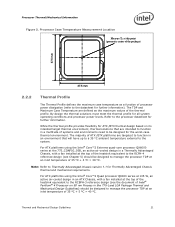
...Refer to 8.167 mm. The IHS height from the top of board is usually minimal. The majority of the processor IHS above the motherboard after the motherboard has been installed into the socket is expected to vary from the package seating plane to the top of the IHS, and ... are no additional components (e.g., BSRAMs that the load applied by the digital thermal sensor and a fan speed control method. One of the key design parameters is the height of the top surface of processor power is a specification used in this package). Note that generate heat on the thermal interface material...
...Refer to 8.167 mm. The IHS height from the top of board is usually minimal. The majority of the processor IHS above the motherboard after the motherboard has been installed into the socket is expected to vary from the package seating plane to the top of the IHS, and ... are no additional components (e.g., BSRAMs that the load applied by the digital thermal sensor and a fan speed control method. One of the key design parameters is the height of the top surface of processor power is a specification used in this package). Note that generate heat on the thermal interface material...
Design Guidelines
Page 21
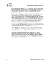
...-case thermal environment. The majority of 35 ºC + 5 ºC = 40 ºC. For ATX platforms using the Intel® Core™2 Extreme quad-core processor QX6000 series at the 775_CONFIG_05B, an active air-cooled design in a Thermally Advantaged Chassis, with a fan installed at the top of the heatsink equivalent to the RCBFH-3 reference design (see the document of...
...-case thermal environment. The majority of 35 ºC + 5 ºC = 40 ºC. For ATX platforms using the Intel® Core™2 Extreme quad-core processor QX6000 series at the 775_CONFIG_05B, an active air-cooled design in a Thermally Advantaged Chassis, with a fan installed at the top of the heatsink equivalent to the RCBFH-3 reference design (see the document of...
Design Guidelines
Page 22
... available chassis solutions. For an example of Intel® Core™2 Extreme quad-core processor QX6000 series at the 775_VR_CONFIG_05B Intel® Core™2 Extreme quad-core processor QX6700 in an ATX platform, its improvement ...fan installed at the top of the heatsink equivalent to the D60188-001 reference design (see the document of Balanced Technology Extended (BTX) System Design Guide ) should be designed to manage the processor TDP at an inlet temperature of 35 ºC + 5 ºC = 40 ºC. Processor Thermal/Mechanical Information For ATX platforms using the Intel® Core...
... available chassis solutions. For an example of Intel® Core™2 Extreme quad-core processor QX6000 series at the 775_VR_CONFIG_05B Intel® Core™2 Extreme quad-core processor QX6700 in an ATX platform, its improvement ...fan installed at the top of the heatsink equivalent to the D60188-001 reference design (see the document of Balanced Technology Extended (BTX) System Design Guide ) should be designed to manage the processor TDP at an inlet temperature of 35 ºC + 5 ºC = 40 ºC. Processor Thermal/Mechanical Information For ATX platforms using the Intel® Core...

Design Guidelines
Page 25
... Beyond a certain heatsink mass, the cost of developing and implementing a heatsink attach mechanism that use Intel reference design structural ingredients is 900 grams. The BTX structural reference component strategy and design is Thermal and...installation in a system and by the real estate available on the motherboard and other design considerations (air duct, etc.). The height of the heatsink must take into account airflow considerations (for fan performance for example) as well as other considerations for component height and placement in the area potentially impacted by the processor...
... Beyond a certain heatsink mass, the cost of developing and implementing a heatsink attach mechanism that use Intel reference design structural ingredients is 900 grams. The BTX structural reference component strategy and design is Thermal and...installation in a system and by the real estate available on the motherboard and other design considerations (air duct, etc.). The height of the heatsink must take into account airflow considerations (for fan performance for example) as well as other considerations for component height and placement in the area potentially impacted by the processor...
Design Guidelines
Page 28
... area. Physical volumetric constraints placed by designing to passive heatsinks, fan heatsinks and system fans are usually combined in Chapter 4. To develop a reliable, cost-effective thermal... to Section 2.1.2.2 for a particular system implementation. Contact your Intel field sales representative for package and heatsink installation and removal is also available. To ease the burden on ...Best Known Methods for cooling integrated circuit devices. Due to protect the processor during sustained workload above TDP. Of particular interest for further information. &#...
... area. Physical volumetric constraints placed by designing to passive heatsinks, fan heatsinks and system fans are usually combined in Chapter 4. To develop a reliable, cost-effective thermal... to Section 2.1.2.2 for a particular system implementation. Contact your Intel field sales representative for package and heatsink installation and removal is also available. To ease the burden on ...Best Known Methods for cooling integrated circuit devices. Due to protect the processor during sustained workload above TDP. Of particular interest for further information. &#...

Design Guidelines
Page 43
...Reference Design Requirements This chapter will document the requirements for an active air-cooled design, with a fan installed at the 775_VR_CONFIG_05B and Intel® Core™2 Extreme processor QX9000 series require a thermal solution equivalent to the RCFH-4 reference design, see Figure 10 for an... view of the heatsink. The thermal technology required for the Intel® RCFH-4 Reference Solution is provided in 0. Thermal and Mechanical Design Guidelines 43 The Intel® Core™2 Extreme quad-core processor QX6000 series at the top of this reference design. Figure ...
...Reference Design Requirements This chapter will document the requirements for an active air-cooled design, with a fan installed at the 775_VR_CONFIG_05B and Intel® Core™2 Extreme processor QX9000 series require a thermal solution equivalent to the RCFH-4 reference design, see Figure 10 for an... view of the heatsink. The thermal technology required for the Intel® RCFH-4 Reference Solution is provided in 0. Thermal and Mechanical Design Guidelines 43 The Intel® Core™2 Extreme quad-core processor QX6000 series at the top of this reference design. Figure ...

Design Guidelines
Page 47
...would conflict with systems in strict compliance with the recommended obstruction height of 88.9 mm for thermal characterization parameter using real processors (based on the methodology described Section 5.3 , and using the TCONTROL specifications described in terms of samples, are reported in...thermal test vehicle correction factors). Intel recommendation is installed 81.28 mm [3.2 in Area A. In particular, for 4 Wire PWM Controlled Fans to use the Fan Specification for the reference heatsink, the Plexiglas* barrier is to implement fan speed control capability based on ...
...would conflict with systems in strict compliance with the recommended obstruction height of 88.9 mm for thermal characterization parameter using real processors (based on the methodology described Section 5.3 , and using the TCONTROL specifications described in terms of samples, are reported in...thermal test vehicle correction factors). Intel recommendation is installed 81.28 mm [3.2 in Area A. In particular, for 4 Wire PWM Controlled Fans to use the Fan Specification for the reference heatsink, the Plexiglas* barrier is to implement fan speed control capability based on ...

Design Guidelines
Page 62
... and initial settings for availability of these tools. 6.4 Fan Hub Thermistor and Intel® QST There is no closed loop control between the installed fans and sensors in tandem to reflect the shipping system configuration. Conversely if the processor workload increases the FSC will command the fan to reduce speed below the VSF curve in response...
... and initial settings for availability of these tools. 6.4 Fan Hub Thermistor and Intel® QST There is no closed loop control between the installed fans and sensors in tandem to reflect the shipping system configuration. Conversely if the processor workload increases the FSC will command the fan to reduce speed below the VSF curve in response...

Design Guidelines
Page 99
... location for the System Monitor Point should be assessed for BTX board suppliers to select a System Monitor thermal sensor location that will be installed. to be too low in this operating state. Thermal and Mechanical Design Guidelines 99 In either case, the temperature of the system. For... There are active, a System Monitor thermal sensor located in the exhaust airflow from the processor diode then the fan speed and system airflow is likely to know the system into which the processor power may be low but other system component powers may be useful to monitor the temperature...
... location for the System Monitor Point should be assessed for BTX board suppliers to select a System Monitor thermal sensor location that will be installed. to be too low in this operating state. Thermal and Mechanical Design Guidelines 99 In either case, the temperature of the system. For... There are active, a System Monitor thermal sensor located in the exhaust airflow from the processor diode then the fan speed and system airflow is likely to know the system into which the processor power may be low but other system component powers may be useful to monitor the temperature...

