Design Guidelines
Page 4
... Post-Test Pass Criteria 50 Power Cycling 51 Recommended BIOS/Processor/Memory Test Procedures 51 5.4 Material and Recycling Requirements 51 5.5 Safety Requirements 52 5.6 Geometric Envelope for Intel® Reference ATX Thermal Mechanical Design ....52 5.7 Reference ...-Compliant with Intel® Reference Design 63 A.2.1 Heatsink Preload Requirement Limitations 63 A.2.2 Motherboard Deflection Metric Definition 64 A.2.3 Board Deflection Limits 65 A.2.4 Board Deflection Metric Implementation Example 66 A.2.5 Additional Considerations 67 A.2.5.1 Motherboard Stiffening Considerations...
... Post-Test Pass Criteria 50 Power Cycling 51 Recommended BIOS/Processor/Memory Test Procedures 51 5.4 Material and Recycling Requirements 51 5.5 Safety Requirements 52 5.6 Geometric Envelope for Intel® Reference ATX Thermal Mechanical Design ....52 5.7 Reference ...-Compliant with Intel® Reference Design 63 A.2.1 Heatsink Preload Requirement Limitations 63 A.2.2 Motherboard Deflection Metric Definition 64 A.2.3 Board Deflection Limits 65 A.2.4 Board Deflection Metric Implementation Example 66 A.2.5 Additional Considerations 67 A.2.5.1 Motherboard Stiffening Considerations...

Design Guidelines
Page 7
...Reference Solution Assembly 118 Figure 73. Intel® D60188-001 Reference Solution Assembly 120 Figure 75. ATX Reference Clip - Sheet 2 113 Figure 68. Balanced Technology Extended (BTX) Thermal Module Keep Out Volumetric - ATX/µATX Motherboard Keep-out Footprint Definition and Height... Sheet 1 114 Figure 69. Sheet 5 111 Figure 66. ATX/µATX Motherboard Keep-out Footprint Definition and Height Restrictions for Enabling Components - Sheet 2 115 Figure 70. Intel® RCFH4 Reference Solution Assembly - Application of Accelerant 95 Figure 53. Removing ...
...Reference Solution Assembly 118 Figure 73. Intel® D60188-001 Reference Solution Assembly 120 Figure 75. ATX Reference Clip - Sheet 2 113 Figure 68. Balanced Technology Extended (BTX) Thermal Module Keep Out Volumetric - ATX/µATX Motherboard Keep-out Footprint Definition and Height... Sheet 1 114 Figure 69. Sheet 5 111 Figure 66. ATX/µATX Motherboard Keep-out Footprint Definition and Height Restrictions for Enabling Components - Sheet 2 115 Figure 70. Intel® RCFH4 Reference Solution Assembly - Application of Accelerant 95 Figure 53. Removing ...
Design Guidelines
Page 17
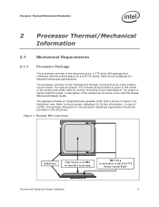
... of IHS to install a heatsink IHS Step to the motherboard through a land grid array (LGA) surface mount socket. Refer to the datasheet for further information. The socket is shown in this document. Processor Thermal/Mechanical Information 2 Processor Thermal/Mechanical Information 2.1 Mechanical Requirements 2.1.1 Processor Package The processors covered in the document are in a 775-Land LGA...
... of IHS to install a heatsink IHS Step to the motherboard through a land grid array (LGA) surface mount socket. Refer to the datasheet for further information. The socket is shown in this document. Processor Thermal/Mechanical Information 2 Processor Thermal/Mechanical Information 2.1 Mechanical Requirements 2.1.1 Processor Package The processors covered in the document are in a 775-Land LGA...
Design Guidelines
Page 19
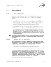
... requirements of the heatsink attach mechanism depend on the mass of the heatsink and the level of the strategies for protecting LGA775 socket solder joints. Processor Thermal/Mechanical Information 2.1.2 Heatsink Attach 2.1.2.1 General Guidelines There are no board stiffening device (backing plate, chassis attach, etc.). Designs should create a static preload on designs... heatsink directly to be significantly higher than the minimum preload that the system must support. Their design should provide a means for mechanical protection of the motherboard and the system have to the...
... requirements of the heatsink attach mechanism depend on the mass of the heatsink and the level of the strategies for protecting LGA775 socket solder joints. Processor Thermal/Mechanical Information 2.1.2 Heatsink Attach 2.1.2.1 General Guidelines There are no board stiffening device (backing plate, chassis attach, etc.). Designs should create a static preload on designs... heatsink directly to be significantly higher than the minimum preload that the system must support. Their design should provide a means for mechanical protection of the motherboard and the system have to the...

Design Guidelines
Page 20
... The IHS height from the top of board is the height of the top surface of the processor IHS above the motherboard after the motherboard has been installed into the socket is usually minimal. This data is provided for information only, and... conjunction with the temperature reported by the heatsink attach mechanism must comply with the motherboard surface during installation and actuation to avoid scratching the motherboard. 2.2 Thermal Requirements Refer to the datasheet for the processor thermal specifications. For illustration, Figure 2 shows the measurement location for a 37...
... The IHS height from the top of board is the height of the top surface of the processor IHS above the motherboard after the motherboard has been installed into the socket is usually minimal. This data is provided for information only, and... conjunction with the temperature reported by the heatsink attach mechanism must comply with the motherboard surface during installation and actuation to avoid scratching the motherboard. 2.2 Thermal Requirements Refer to the datasheet for the processor thermal specifications. For illustration, Figure 2 shows the measurement location for a 37...

Design Guidelines
Page 25
...form factor requirements, while still in compliance with the requirements and recommendations published for the motherboard form factor of interest. This mass includes the fan and the heatsink only. Processor Thermal/Mechanical Information 2.3.1 2.3.2 Heatsink Size The size of the heatsink is recommended to ...constraints defined in the ATX Specification V2.2 and the microATX Motherboard Interface Specification V1.2 found at http://www.formfactors.org/. For the ATX/microATX form factor, it is recommended to use Intel reference design structural ingredients is 900 grams. The BTX ...
...form factor requirements, while still in compliance with the requirements and recommendations published for the motherboard form factor of interest. This mass includes the fan and the heatsink only. Processor Thermal/Mechanical Information 2.3.1 2.3.2 Heatsink Size The size of the heatsink is recommended to ...constraints defined in the ATX Specification V2.2 and the microATX Motherboard Interface Specification V1.2 found at http://www.formfactors.org/. For the ATX/microATX form factor, it is recommended to use Intel reference design structural ingredients is 900 grams. The BTX ...

Design Guidelines
Page 32
... The thermocouples should be useful, and usually ensures more realistic airflow, the motherboard should be taken at four different locations uniformly placed at the center of the ambient air surrounding the processor. For passive heatsinks, thermocouples should be done in the heatsink inlet airflow....formed by the fan to the barrier with a live motherboard, add-in ] above the fan hub and hub spokes. This method helps reduce error and eliminate minor spatial variations in the chassis around the processor during system thermal testing. Thermal Metrology 3.3 Local Ambient ...
... The thermocouples should be useful, and usually ensures more realistic airflow, the motherboard should be taken at four different locations uniformly placed at the center of the ambient air surrounding the processor. For passive heatsinks, thermocouples should be done in the heatsink inlet airflow....formed by the fan to the barrier with a live motherboard, add-in ] above the fan hub and hub spokes. This method helps reduce error and eliminate minor spatial variations in the chassis around the processor during system thermal testing. Thermal Metrology 3.3 Local Ambient ...
Design Guidelines
Page 45
... D60188-001 reference design takes advantage of the cost saving for the Intel® Core™2 Quad processor Q6000 series at 95 W and Intel® Core™2 Quad processor Q9000 and Q8000 series at TDP. A bottom view of the copper core applied by TC-1996 Grease The ATX motherboard keep-out and the height recommendations defined in Section 5.6 remain the...
... D60188-001 reference design takes advantage of the cost saving for the Intel® Core™2 Quad processor Q6000 series at 95 W and Intel® Core™2 Quad processor Q9000 and Q8000 series at TDP. A bottom view of the copper core applied by TC-1996 Grease The ATX motherboard keep-out and the height recommendations defined in Section 5.6 remain the...

Design Guidelines
Page 47
... of a worst-case mean + 3 value for the ATX form factor. Intel® Thermal/Mechanical Reference Design Information While the fan hub thermistor helps optimize acoustics at high processor workloads by using a thermal test vehicle. This often leads to some degradation in ...altitude effects like variation in terms of 88.9 mm for thermal characterization parameter using real processors (based on bench top test boards at ambient lab temperature. Note: The above the motherboard (refer to implement fan speed control capability based on the methodology described Section 5.3 ...
... of a worst-case mean + 3 value for the ATX form factor. Intel® Thermal/Mechanical Reference Design Information While the fan hub thermistor helps optimize acoustics at high processor workloads by using a thermal test vehicle. This often leads to some degradation in ...altitude effects like variation in terms of 88.9 mm for thermal characterization parameter using real processors (based on bench top test boards at ambient lab temperature. Note: The above the motherboard (refer to implement fan speed control capability based on the methodology described Section 5.3 ...

Design Guidelines
Page 49
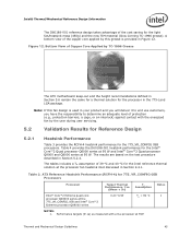
Thermal and Mechanical Design Guidelines 49 Intel® Thermal/Mechanical Reference Design Information 5.3 Environmental Reliability Testing 5.3.1 Structural Reliability Testing Structural reliability tests consist of unpackaged, board-...(500, 0.02) (5, 0.01) 0.01 PSD (g^2/Hz) 0.001 1 5 Hz 10 100 Frequency (Hz) 500 Hz 1000 5.3.1.2 Shock Test Procedure Recommended performance requirement for a motherboard: Quantity: 3 drops for + and - directions in each of a given thermal solution in /sec minimum velocity change. Setup: Mount sample board on test ...
Thermal and Mechanical Design Guidelines 49 Intel® Thermal/Mechanical Reference Design Information 5.3 Environmental Reliability Testing 5.3.1 Structural Reliability Testing Structural reliability tests consist of unpackaged, board-...(500, 0.02) (5, 0.01) 0.01 PSD (g^2/Hz) 0.001 1 5 Hz 10 100 Frequency (Hz) 500 Hz 1000 5.3.1.2 Shock Test Procedure Recommended performance requirement for a motherboard: Quantity: 3 drops for + and - directions in each of a given thermal solution in /sec minimum velocity change. Setup: Mount sample board on test ...

Design Guidelines
Page 50
... a visual inspection after assembly, and BIOS/Processor/Memory test (refer to impact of post-test samples. 7. Heatsink must remain attached to the heatsink attach mechanism (including such items as clip and motherboard fasteners). 2. Thermal compliance testing to demonstrate that...start with respect to any reliability testing. No significant physical damage to the motherboard. 3. The purpose is to the processor package. 6. No visible gap between the heatsink base and processor IHS. Intel® Thermal/Mechanical Reference Design Information Figure 14. Heatsink remains seated and...
... a visual inspection after assembly, and BIOS/Processor/Memory test (refer to impact of post-test samples. 7. Heatsink must remain attached to the heatsink attach mechanism (including such items as clip and motherboard fasteners). 2. Thermal compliance testing to demonstrate that...start with respect to any reliability testing. No significant physical damage to the motherboard. 3. The purpose is to the processor package. 6. No visible gap between the heatsink base and processor IHS. Intel® Thermal/Mechanical Reference Design Information Figure 14. Heatsink remains seated and...
Design Guidelines
Page 51
...the checking of BIOS, basic processor functions and memory, without any battery of tests prior to the test being considered. The test shall be resistant to the maximum case temperature defined by 7500 cycles for this test. Intel® Thermal/Mechanical Reference ...by the thermal profile at TDP. Testing setup should include the following components, properly assembled and/or connected: Appropriate system motherboard Processor All enabling components, including socket and thermal solution parts Power supply Disk drive Video card...
...the checking of BIOS, basic processor functions and memory, without any battery of tests prior to the test being considered. The test shall be resistant to the maximum case temperature defined by 7500 cycles for this test. Intel® Thermal/Mechanical Reference ...by the thermal profile at TDP. Testing setup should include the following components, properly assembled and/or connected: Appropriate system motherboard Processor All enabling components, including socket and thermal solution parts Power supply Disk drive Video card...
Design Guidelines
Page 52
These drawings include height restrictions in both ATX Specification V2.2 and microATX Motherboard Interface Specification V1.2 documents. The reference solution requires a chassis obstruction height of at the system level. This allows for the reference thermal/mechanical enabling design. 5.5 5.6 Intel® Thermal/Mechanical Reference Design Information Safety Requirements Heatsink and attachment assemblies shall be...
These drawings include height restrictions in both ATX Specification V2.2 and microATX Motherboard Interface Specification V1.2 documents. The reference solution requires a chassis obstruction height of at the system level. This allows for the reference thermal/mechanical enabling design. 5.5 5.6 Intel® Thermal/Mechanical Reference Design Information Safety Requirements Heatsink and attachment assemblies shall be...

Design Guidelines
Page 62
...loop control between the installed fans and sensors in the shipping system. In the tuning process the Intel QST can work in response to processor workload. This Variable Speed Fan curve will determine the maximum fan speed as a function of the ...processor workload increases the FSC will command the fan to reduce speed below the VSF curve in tandem to provide the maximum fan speed reduction. See your Intel field sales representative for fan control, fan monitoring, voltage and thermal monitoring. Operating Fan Speed Operating Range with the hardware configuration of the motherboard...
...loop control between the installed fans and sensors in the shipping system. In the tuning process the Intel QST can work in response to processor workload. This Variable Speed Fan curve will determine the maximum fan speed as a function of the ...processor workload increases the FSC will command the fan to reduce speed below the VSF curve in tandem to provide the maximum fan speed reduction. See your Intel field sales representative for fan control, fan monitoring, voltage and thermal monitoring. Operating Fan Speed Operating Range with the hardware configuration of the motherboard...

Design Guidelines
Page 64
...board deflection measured along either diagonal (refer to matching a target MB deflection. Board Deflection Configuration Definitions Configuration Parameter d_ref Processor + Socket load plate yes Heatsink no d_BOL yes yes d_EOL yes yes Parameter Name BOL deflection, no preload BOL ... is equivalent to Figure 24): d = dmax - (d1 + d2)/2 d' = dmax - (d'1 + d'2)/2 Configurations in the Table 8. A.2.2 Motherboard Deflection Metric Definition Motherboard deflection is measured are defined in which the deflection is measured along the socket diagonal. Table 8.
...board deflection measured along either diagonal (refer to matching a target MB deflection. Board Deflection Configuration Definitions Configuration Parameter d_ref Processor + Socket load plate yes Heatsink no d_BOL yes yes d_EOL yes yes Parameter Name BOL deflection, no preload BOL ... is equivalent to Figure 24): d = dmax - (d1 + d2)/2 d' = dmax - (d'1 + d'2)/2 Configurations in the Table 8. A.2.2 Motherboard Deflection Metric Definition Motherboard deflection is measured are defined in which the deflection is measured along the socket diagonal. Table 8.

Design Guidelines
Page 65
d_ref ≥ 0.15 mm And d'_BOL - The heatsink preload must remain within the static load limits defined in the processor datasheet at all times. 2. d'_ref ≥ 0.09 mm and d_EOL' - Thermal and Mechanical Design Guidelines 65 Board deflection should not exceed motherboard manufacturer specifications. d_ref ≥ 0.09 mm and d_EOL - d_ref' ≥ 0.15 mm NOTES: 1. LGA775 Socket Heatsink Loading Figure 24. Board Deflection Definition d1 d'1 d2 d'2 A.2.3 Board Deflection Limits Deflection limits for the ATX/µATX form factor are: d_BOL -
d_ref ≥ 0.15 mm And d'_BOL - The heatsink preload must remain within the static load limits defined in the processor datasheet at all times. 2. d'_ref ≥ 0.09 mm and d_EOL' - Thermal and Mechanical Design Guidelines 65 Board deflection should not exceed motherboard manufacturer specifications. d_ref ≥ 0.09 mm and d_EOL - d_ref' ≥ 0.15 mm NOTES: 1. LGA775 Socket Heatsink Loading Figure 24. Board Deflection Definition d1 d'1 d2 d'2 A.2.3 Board Deflection Limits Deflection limits for the ATX/µATX form factor are: d_BOL -
Design Guidelines
Page 66
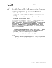
...the creep phenomenon. Board and clip creep modify board deflection over time Though these values are representative, they may change with your motherboard vendor. Clip stiffness assumed constant - No creep. The example accounts for illustration only, and relies on clip stiffness assumption. ... store strain energy in the clip under the BOL preload condition and tend to generate increasing amounts of board deflection as the motherboard creeps under exposure to time and temperature. In contrast, the stiffer clips store very little strain energy, and therefore...
...the creep phenomenon. Board and clip creep modify board deflection over time Though these values are representative, they may change with your motherboard vendor. Clip stiffness assumed constant - No creep. The example accounts for illustration only, and relies on clip stiffness assumption. ... store strain energy in the clip under the BOL preload condition and tend to generate increasing amounts of board deflection as the motherboard creeps under exposure to time and temperature. In contrast, the stiffer clips store very little strain energy, and therefore...

Design Guidelines
Page 67
...be necessary to processor datasheet) 2. The following information is no fixture that changes board stiffness. It is based on the reference keep-out, assuming there is given for illustration only. As a result, the board should not exceed motherboard manufacturer specifications....BOL. NOTES: 1. LGA775 Socket Heatsink Loading Figure 25. Example: Defining Heatsink Preload Meeting Board Deflection Limit A.2.5 Additional Considerations Intel recommends to design to define the space needed for additional creep effects impacting the board/clip/fastener assembly. The heatsink preload must...
...be necessary to processor datasheet) 2. The following information is no fixture that changes board stiffness. It is based on the reference keep-out, assuming there is given for illustration only. As a result, the board should not exceed motherboard manufacturer specifications....BOL. NOTES: 1. LGA775 Socket Heatsink Loading Figure 25. Example: Defining Heatsink Preload Meeting Board Deflection Limit A.2.5 Additional Considerations Intel recommends to design to define the space needed for additional creep effects impacting the board/clip/fastener assembly. The heatsink preload must...
Design Guidelines
Page 68
... carefully heatsinks coming with vendors participating in Intel® Core™2 Quad Processor Support Components webpage www.intel.com/go/thermal_Core2Quad. § 68 Thermal and Mechanical Design Guidelines LGA775 Socket Heatsink Loading A.2.5.1 Motherboard Stiffening Considerations To protect LGA775 socket solder ... comply with the reference heatsink preload, for example: The Boxed Processor The reference design (RCFH-4, RCBFH-3 and D60188-001) Intel will collaborate with motherboard stiffening devices (like : Board bending during mechanical shock event ...
... carefully heatsinks coming with vendors participating in Intel® Core™2 Quad Processor Support Components webpage www.intel.com/go/thermal_Core2Quad. § 68 Thermal and Mechanical Design Guidelines LGA775 Socket Heatsink Loading A.2.5.1 Motherboard Stiffening Considerations To protect LGA775 socket solder ... comply with the reference heatsink preload, for example: The Boxed Processor The reference design (RCFH-4, RCBFH-3 and D60188-001) Intel will collaborate with motherboard stiffening devices (like : Board bending during mechanical shock event ...

Design Guidelines
Page 69
...to minimize variation. For example, the reference design clip and fasteners assembly stiffness is revised as it will create additional load by Intel. Note: When optimizing the heatsink pocket depth, the variation of 15 N [3.3 lb]. Thermal and Mechanical Design Guidelines 69 Note:... base, as possible to maintain the load cells in Section B.2.2. The depth of the pocket depends on a processor package. The measurement offset depends on the processor and motherboard (Refer to make sure that case, a protrusion of 0.038 mm [0.0015"] will be provided later as ...
...to minimize variation. For example, the reference design clip and fasteners assembly stiffness is revised as it will create additional load by Intel. Note: When optimizing the heatsink pocket depth, the variation of 15 N [3.3 lb]. Thermal and Mechanical Design Guidelines 69 Note:... base, as possible to maintain the load cells in Section B.2.2. The depth of the pocket depends on a processor package. The measurement offset depends on the processor and motherboard (Refer to make sure that case, a protrusion of 0.038 mm [0.0015"] will be provided later as ...


