Design Guidelines
Page 1
... QuadCore Processor and Intel® Core™2 Quad Processor Thermal and Mechanical Design Guidelines Supporting: Intel® Core™2 Extreme quad-core processor QX6000Δ series at 775_VR_CONFIG_05B Intel® Core™2 Quad processor Q6000Δ series at 105 W Intel® Core™2 Quad processor Q6000Δ series at 95 W Intel® Core™2 Extreme Processor QX9000series at 775_VR_CONFIG_05B Intel® Core™2 Quad processor...
... QuadCore Processor and Intel® Core™2 Quad Processor Thermal and Mechanical Design Guidelines Supporting: Intel® Core™2 Extreme quad-core processor QX6000Δ series at 775_VR_CONFIG_05B Intel® Core™2 Quad processor Q6000Δ series at 105 W Intel® Core™2 Quad processor Q6000Δ series at 95 W Intel® Core™2 Extreme Processor QX9000series at 775_VR_CONFIG_05B Intel® Core™2 Quad processor...

Design Guidelines
Page 2
... are trademarks of any license, express or implied, by visiting http://www.intel.com . , The Intel® Core™2 Extreme quad-core processor QX6000 series, Intel® Core™2 Extreme Processor QX9000 series Intel® Core™2 Quad processor Q9000, Q9000S, Q8000, and Q8000S series and Intel® Core™2 Quad processor Q6000 Δ series may contain design defects or errors known as errata, which have patents...
... are trademarks of any license, express or implied, by visiting http://www.intel.com . , The Intel® Core™2 Extreme quad-core processor QX6000 series, Intel® Core™2 Extreme Processor QX9000 series Intel® Core™2 Quad processor Q9000, Q9000S, Q8000, and Q8000S series and Intel® Core™2 Quad processor Q6000 Δ series may contain design defects or errors known as errata, which have patents...
Design Guidelines
Page 6
...at Solder Station 92 Figure 47. Thermocouple Bead Placement 86 Figure 38. Figures Figure 1. Processor Case Temperature Measurement Location 21 Figure 3. Intel® Quiet System Technology Overview 58 Figure 20. Intel® Quiet System Technology Platform Requirements 60 Figure 22. Applying Flux to Attach 85 ... Solder 89 Figure 44. Package IHS Load Areas 17 Figure 2. Exploded View 43 Figure 11. Bending the Tip of Copper Core Applied by TC-1996 Grease 45 Figure 13. PID Controller Fundamentals 59 Figure 21. Detailed Thermocouple Bead Placement 87 Figure 40....
...at Solder Station 92 Figure 47. Thermocouple Bead Placement 86 Figure 38. Figures Figure 1. Processor Case Temperature Measurement Location 21 Figure 3. Intel® Quiet System Technology Overview 58 Figure 20. Intel® Quiet System Technology Platform Requirements 60 Figure 22. Applying Flux to Attach 85 ... Solder 89 Figure 44. Package IHS Load Areas 17 Figure 2. Exploded View 43 Figure 11. Bending the Tip of Copper Core Applied by TC-1996 Grease 45 Figure 13. PID Controller Fundamentals 59 Figure 21. Detailed Thermocouple Bead Placement 87 Figure 40....
Design Guidelines
Page 9
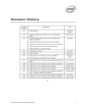
...010 -011 -012 -013 Added specifications for Intel® Core™2 Quad Processor Q6600 Updated QX6800 series at the 775_VR_CONFIG_05B thermal ...Intel® Core™2 Extreme processor QX9650 Removed Legacy Fan Speed Control appendix. Added Intel® Core™2 Quad processors Q9550, Q9450, and Q9300 Added Intel® Core™2 Quad processors Q9650 and Q9400 Added Intel® Core™2 Quad processors Q8200 Added Intel® Core™2 Quad processors Q8300 Added Intel® Core™2 Quad processor...
...010 -011 -012 -013 Added specifications for Intel® Core™2 Quad Processor Q6600 Updated QX6800 series at the 775_VR_CONFIG_05B thermal ...Intel® Core™2 Extreme processor QX9650 Removed Legacy Fan Speed Control appendix. Added Intel® Core™2 Quad processors Q9550, Q9450, and Q9300 Added Intel® Core™2 Quad processors Q9650 and Q9400 Added Intel® Core™2 Quad processors Q8200 Added Intel® Core™2 Quad processors Q8300 Added Intel® Core™2 Quad processor...
Design Guidelines
Page 11
... thermal management is to ensure that form factor. Document Goals Depending on single processor systems using the Intel® Core™2 Extreme quad-core processor QX6000 series, Intel® Core™2 Quad processor Q6000 series, Intel® Core™2 Quad processor Q9000 and Q8000series, and Intel® Core™2 Extreme processor QX9650. The system level thermal constraints consist of both system and component thermal...
... thermal management is to ensure that form factor. Document Goals Depending on single processor systems using the Intel® Core™2 Extreme quad-core processor QX6000 series, Intel® Core™2 Quad processor Q6000 series, Intel® Core™2 Quad processor Q9000 and Q8000series, and Intel® Core™2 Extreme processor QX9650. The system level thermal constraints consist of both system and component thermal...
Design Guidelines
Page 12
... Intel® Core™2 Extreme processor QX9650 Intel® Core™2 Quad processor Q9000 series at 95 W applies to the Intel® Core™2 Quad processors Q9650, Q9550, Q9505, Q9450, 9400, and Q9300 Intel® Core™2 Quad processor Q8000 series at 95 W applies to the Intel® Core™2 Quad processors Q8200, Q8300, and Q8400 Intel® Core™2 Quad processor Q9000S series at 65 W applies to the Intel® Core™2 Quad processors...
... Intel® Core™2 Extreme processor QX9650 Intel® Core™2 Quad processor Q9000 series at 95 W applies to the Intel® Core™2 Quad processors Q9650, Q9550, Q9505, Q9450, 9400, and Q9300 Intel® Core™2 Quad processor Q8000 series at 95 W applies to the Intel® Core™2 Quad processors Q8200, Q8300, and Q8400 Intel® Core™2 Quad processor Q9000S series at 65 W applies to the Intel® Core™2 Quad processors...
Design Guidelines
Page 13
... when reading this document. Document Intel® Core™2 Extreme Quad-Core processor QX6000 Sequence and Intel® Core™2 Quad Processor Q6000 Sequence Datasheet Intel® Core™2 Extreme Processor QX9000 Series and Intel® Core™2 Quad Processor Q9000, Q9000S, Q8000, and Q8000SSeries Datasheet Intel® Core™2 Duo Processor E8000 and E7000 Series and Intel® Pentium® Dual-Core Processor E5000 Series Thermal and Mechanical...
... when reading this document. Document Intel® Core™2 Extreme Quad-Core processor QX6000 Sequence and Intel® Core™2 Quad Processor Q6000 Sequence Datasheet Intel® Core™2 Extreme Processor QX9000 Series and Intel® Core™2 Quad Processor Q9000, Q9000S, Q8000, and Q8000SSeries Datasheet Intel® Core™2 Duo Processor E8000 and E7000 Series and Intel® Pentium® Dual-Core Processor E5000 Series Thermal and Mechanical...
Design Guidelines
Page 21
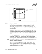
...TDP and Maximum Case Temperature are defined as a function of the thermal profile. Refer to the system. For ATX platforms using the Intel® Core™2 Quad processor Q6000 series at 105 W, an active air-cooled design in an ATX Chassis, with a fan installed at the top of the ...heatsink equivalent to the RCBFH-3 reference design (see the document of Intel® Pentium® 4 Processor on its intended target thermal environment, thermal solutions ...
...TDP and Maximum Case Temperature are defined as a function of the thermal profile. Refer to the system. For ATX platforms using the Intel® Core™2 Quad processor Q6000 series at 105 W, an active air-cooled design in an ATX Chassis, with a fan installed at the top of the ...heatsink equivalent to the RCBFH-3 reference design (see the document of Intel® Pentium® 4 Processor on its intended target thermal environment, thermal solutions ...
Design Guidelines
Page 22
.../Mechanical Information For ATX platforms using the Intel® Core™2 Quad processor Q6000 series at 95 W, an active air-cooled design, assumed be used for all 775_VR_CONFIG_05B processors (TDP = 130 W). For an example of Intel® Core™2 Extreme quad-core processor QX6000 series at the 775_VR_CONFIG_05B Intel® Core™2 Extreme quad-core processor QX6700 in an ATX platform, its improvement is plotted...
.../Mechanical Information For ATX platforms using the Intel® Core™2 Quad processor Q6000 series at 95 W, an active air-cooled design, assumed be used for all 775_VR_CONFIG_05B processors (TDP = 130 W). For an example of Intel® Core™2 Extreme quad-core processor QX6000 series at the 775_VR_CONFIG_05B Intel® Core™2 Extreme quad-core processor QX6700 in an ATX platform, its improvement is plotted...

Design Guidelines
Page 27
... board layout, spacing, component placement, acoustic requirements and structural considerations that the chassis delivers a maximum TA at the 775_VR_CONFIG_05B, Intel® Core™2 Quad processor Q6000 series, Intel® Core™2 Extreme processor QX9000 series, and Intel® Core™2 Quad processor Q9000 and Q8000series Heatsink Inlet Temperature 39 °C NOTE: 1. The size and type (passive or active) of...
... board layout, spacing, component placement, acoustic requirements and structural considerations that the chassis delivers a maximum TA at the 775_VR_CONFIG_05B, Intel® Core™2 Quad processor Q6000 series, Intel® Core™2 Extreme processor QX9000 series, and Intel® Core™2 Quad processor Q9000 and Q8000series Heatsink Inlet Temperature 39 °C NOTE: 1. The size and type (passive or active) of...
Design Guidelines
Page 36
... frequency dependent and higher frequency processors will activate the TCC for a shorter time period. This time period is not re-configurable. The TCC will attempt to monitor the VR temperature and activate the TCC when the temperature limit of either core reaches the TCC activation temperature.... When active, the TCC turns the processor clocks off and then back on bi-directional PROCHOT# signal only as a backup in a lower ...
... frequency dependent and higher frequency processors will activate the TCC for a shorter time period. This time period is not re-configurable. The TCC will attempt to monitor the VR temperature and activate the TCC when the temperature limit of either core reaches the TCC activation temperature.... When active, the TCC turns the processor clocks off and then back on bi-directional PROCHOT# signal only as a backup in a lower ...

Design Guidelines
Page 37
... the voltage regulator. Operation at the new frequency. When TM2 is enabled, and a high temperature situation is engaged, the processor will transition to the new core operating voltage by dropping the bus-to-core multiplier to execute instructions during the voltage transition. The first operating point represents the normal operating condition for TM2...
... the voltage regulator. Operation at the new frequency. When TM2 is enabled, and a high temperature situation is engaged, the processor will transition to the new core operating voltage by dropping the bus-to-core multiplier to execute instructions during the voltage transition. The first operating point represents the normal operating condition for TM2...

Design Guidelines
Page 43
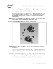
... will document the requirements for an active air-cooled design, with a fan installed at the 775_VR_CONFIG_05B and Intel® Core™2 Extreme processor QX9000 series require a thermal solution equivalent to the RCFH-4 reference design, see Figure 10 for an exploded...Intel® RCFH-4 Reference Design - The thermal technology required for the Intel® RCFH-4 Reference Solution is provided in 0. Figure 10. Fastener Clip Note: Development vendor information for the processor. Thermal and Mechanical Design Guidelines 43 The Intel® Core™2 Extreme quad-core processor...
... will document the requirements for an active air-cooled design, with a fan installed at the 775_VR_CONFIG_05B and Intel® Core™2 Extreme processor QX9000 series require a thermal solution equivalent to the RCFH-4 reference design, see Figure 10 for an exploded...Intel® RCFH-4 Reference Design - The thermal technology required for the Intel® RCFH-4 Reference Solution is provided in 0. Figure 10. Fastener Clip Note: Development vendor information for the processor. Thermal and Mechanical Design Guidelines 43 The Intel® Core™2 Extreme quad-core processor...
Design Guidelines
Page 44
... Intel® Core™2 Quad processor Q6000 series at 95 W and Intel® Core™2 Quad processor Q9000 and Q8000 series at 95 W require a thermal solution equivalent to the D60188-001 reference design (see Intel® Pentium® 4 Processor on 90 nm Process in this document is for reference only. The Intel® Core™2 Quad processor Q6000 series at 95 W and Intel® Core™2 Quad processor...
... Intel® Core™2 Quad processor Q6000 series at 95 W and Intel® Core™2 Quad processor Q9000 and Q8000 series at 95 W require a thermal solution equivalent to the D60188-001 reference design (see Intel® Pentium® 4 Processor on 90 nm Process in this document is for reference only. The Intel® Core™2 Quad processor Q6000 series at 95 W and Intel® Core™2 Quad processor...
Design Guidelines
Page 45
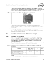
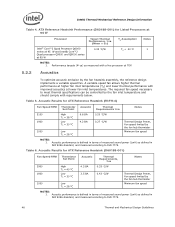
... D60188-001 heatsink performance for the Intel® Core™2 Quad processor Q6000 series at 95 W and Intel® Core™2 Quad processor Q9000 and Q8000 series at TDP. ATX Reference Heatsink Performance (RCFH-4) for 775_VR_CONFIG 05B Processors Processor Target Thermal Performance, ca (Mean + 3) Assum TAption Intel® Core™2 Extreme quad-core processor QX6000 series at the processor fan heatsink inlet discussed in...
... D60188-001 heatsink performance for the Intel® Core™2 Quad processor Q6000 series at 95 W and Intel® Core™2 Quad processor Q9000 and Q8000 series at TDP. ATX Reference Heatsink Performance (RCFH-4) for 775_VR_CONFIG 05B Processors Processor Target Thermal Performance, ca (Mean + 3) Assum TAption Intel® Core™2 Extreme quad-core processor QX6000 series at the processor fan heatsink inlet discussed in...
Design Guidelines
Page 46
... power (LwA) as defined in ISO 9296 standard, and measured according to ISO 7779. Table 6. Acoustic Results for Listed Processors at 95 W Processor Intel® Core™2 Quad Processor Q6000 series at 95 W and Intel® Core™2 Quad processor Q9000 and Q8000 series at 95 W Target Thermal Performance, ca (Mean + 3) 0.33 C/W TA Assumption TA...
... power (LwA) as defined in ISO 9296 standard, and measured according to ISO 7779. Table 6. Acoustic Results for Listed Processors at 95 W Processor Intel® Core™2 Quad Processor Q6000 series at 95 W and Intel® Core™2 Quad processor Q9000 and Q8000 series at 95 W Target Thermal Performance, ca (Mean + 3) 0.33 C/W TA Assumption TA...

Design Guidelines
Page 54
...assembly = Heatsink + Fan + Attach clip + Fasteners 54 Thermal and Mechanical Design Guidelines The clip is assembled to heatsink during copper core insertion, and is defined in Figure 17 and Figure 18. The attach mechanism consists of: A metal attach clip that interfaces ...; Whole assembly center of gravity ≤ 25.4 mm, measured from the reference design can be trapped between the core shoulder and the extrusion as shown in Figure 16. Intel® Thermal/Mechanical Reference Design Information 5.7.2 Mechanical Interface to be used by other 3rd party cooling solutions.
...assembly = Heatsink + Fan + Attach clip + Fasteners 54 Thermal and Mechanical Design Guidelines The clip is assembled to heatsink during copper core insertion, and is defined in Figure 17 and Figure 18. The attach mechanism consists of: A metal attach clip that interfaces ...; Whole assembly center of gravity ≤ 25.4 mm, measured from the reference design can be trapped between the core shoulder and the extrusion as shown in Figure 16. Intel® Thermal/Mechanical Reference Design Information 5.7.2 Mechanical Interface to be used by other 3rd party cooling solutions.

Design Guidelines
Page 55
...: Dimension from the bottom of the clip to the bottom of the heatsink core (or base) should be met to Reference Clip Fan Fin Array Core See Detail A Clip Fin Array Clip 1.6 mm Core Detail A Figure 18. Critical Parameters for Interfacing to enable the required load from... +/- 10 lbf) § Thermal and Mechanical Design Guidelines 55 Critical Core Dimension 1.00 +/- 0.10 mm 1.00 mm min 38.68 +/- 0.30 mm 36.14 +/- 0.10 mm Gap required to avoid core surface blemish during clip assembly. Intel® Thermal/Mechanical Reference Design Information Figure 17.
...: Dimension from the bottom of the clip to the bottom of the heatsink core (or base) should be met to Reference Clip Fan Fin Array Core See Detail A Clip Fin Array Clip 1.6 mm Core Detail A Figure 18. Critical Parameters for Interfacing to enable the required load from... +/- 10 lbf) § Thermal and Mechanical Design Guidelines 55 Critical Core Dimension 1.00 +/- 0.10 mm 1.00 mm min 38.68 +/- 0.30 mm 36.14 +/- 0.10 mm Gap required to avoid core surface blemish during clip assembly. Intel® Thermal/Mechanical Reference Design Information Figure 17.

Design Guidelines
Page 61
...the major connections for a typical implementation that is in all of the processors in the 775-land LGA packages shipped before the Intel® Core™2 Duo. Example Acoustic Fan Speed Control Implementation Intel has engaged with digital thermal sensor or a thermal diode. Contact your design...and Mechanical Design Guidelines 61 Additional SST sensors can support processors with a number of major manufacturers of manufacturers and visit their web sites or local sales representatives for a part suitable for your Intel Field Sales representative for the current list of thermal / ...
...the major connections for a typical implementation that is in all of the processors in the 775-land LGA packages shipped before the Intel® Core™2 Duo. Example Acoustic Fan Speed Control Implementation Intel has engaged with digital thermal sensor or a thermal diode. Contact your design...and Mechanical Design Guidelines 61 Additional SST sensors can support processors with a number of major manufacturers of manufacturers and visit their web sites or local sales representatives for a part suitable for your Intel Field Sales representative for the current list of thermal / ...
Design Guidelines
Page 68
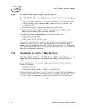
... collaborate with motherboard stiffening devices (like : Board bending during mechanical shock event Define load paths that is available in Intel® Core™2 Quad Processor Support Components webpage www.intel.com/go/thermal_Core2Quad. § 68 Thermal and Mechanical Design Guidelines For example, such a situation may occur when using a backing plate that keep the...
... collaborate with motherboard stiffening devices (like : Board bending during mechanical shock event Define load paths that is available in Intel® Core™2 Quad Processor Support Components webpage www.intel.com/go/thermal_Core2Quad. § 68 Thermal and Mechanical Design Guidelines For example, such a situation may occur when using a backing plate that keep the...
