

Product Guide
Page 5
Contents 1 Desktop Board Features Supported Operating Systems 11 Desktop Board Components 12 Processor ...14 Intel® H55 Express Chipset 14 Main Memory...15 Graphics Subsystem 15 Integrated Graphics 15 Analog Display (VGA 15 High-Definition Multimedia ...PCI Express Auto Configuration 19 Security Passwords 19 Hardware Management 20 Hardware Monitoring and Fan Speed Control 20 Fan Monitoring 20 Power Management 21 Software Support 21 ACPI 21 Hardware Support 21 Power Connectors 21 Fan Headers 21 LAN Wake Capabilities 22 Instantly Available PC Technology 22 +5 V Standby...
Contents 1 Desktop Board Features Supported Operating Systems 11 Desktop Board Components 12 Processor ...14 Intel® H55 Express Chipset 14 Main Memory...15 Graphics Subsystem 15 Integrated Graphics 15 Analog Display (VGA 15 High-Definition Multimedia ...PCI Express Auto Configuration 19 Security Passwords 19 Hardware Management 20 Hardware Monitoring and Fan Speed Control 20 Fan Monitoring 20 Power Management 21 Software Support 21 ACPI 21 Hardware Support 21 Power Connectors 21 Fan Headers 21 LAN Wake Capabilities 22 Instantly Available PC Technology 22 +5 V Standby...
Product Guide
Page 6
Intel Desktop Board DH55TC Product Guide 2 Installing and Replacing Desktop Board Components Before You Begin 27 Installation Precautions 28 Prevent Power Supply Overload 28 Observe Safety and Regulatory Requirements 28 Installing the I/O Shield 29 Installing and Removing the Desktop Board 30 ... Cables 52 Connecting Chassis Fan Cables 52 Connecting Power Supply Cables 53 Setting the BIOS Configuration Jumper 54 Clearing Passwords 55 Replacing the Battery 56 3 Updating the BIOS Updating the BIOS with the Intel® Express BIOS Update Utility 63 Updating the BIOS with the ISO...
Intel Desktop Board DH55TC Product Guide 2 Installing and Replacing Desktop Board Components Before You Begin 27 Installation Precautions 28 Prevent Power Supply Overload 28 Observe Safety and Regulatory Requirements 28 Installing the I/O Shield 29 Installing and Removing the Desktop Board 30 ... Cables 52 Connecting Chassis Fan Cables 52 Connecting Power Supply Cables 53 Setting the BIOS Configuration Jumper 54 Clearing Passwords 55 Replacing the Battery 56 3 Updating the BIOS Updating the BIOS with the Intel® Express BIOS Update Utility 63 Updating the BIOS with the ISO...
Product Guide
Page 7
...Connectors 51 25. Secure the Load Plate in Place 35 13. Installing an Intel Z-U130 USB Solid-State Drive (or Compatible Device 45 23. Connecting Power Supply Cables 53 27. Intel Desktop Board DH55TC China RoHS Material Self Declaration Table 77 vii LAN Connector LEDs 17 3. Unlatch ...2LI/Pb-free 2LI Board 74 Restriction of the Standby Power Indicator 23 4. Install the Processor 34 11. Location of the BIOS Configuration Jumper Block 54 28. Location of the Chassis Fan Headers 52 26. Intel Desktop Board DH55TC Components 12 2. Installing a PCI Express x16 Graphics ...
...Connectors 51 25. Secure the Load Plate in Place 35 13. Installing an Intel Z-U130 USB Solid-State Drive (or Compatible Device 45 23. Connecting Power Supply Cables 53 27. Intel Desktop Board DH55TC China RoHS Material Self Declaration Table 77 vii LAN Connector LEDs 17 3. Unlatch ...2LI/Pb-free 2LI Board 74 Restriction of the Standby Power Indicator 23 4. Install the Processor 34 11. Location of the BIOS Configuration Jumper Block 54 28. Location of the Chassis Fan Headers 52 26. Intel Desktop Board DH55TC Components 12 2. Installing a PCI Express x16 Graphics ...
Product Guide
Page 8
...the BIOS Setup Program Modes 55 15. BIOS Beep Codes 67 16. Product Certification Markings 80 viii BIOS Error Messages 68 18. Intel Desktop Board DH55TC Components 13 3. USB 2.0 Header Signal Names 50 13. Lead-Free Second Level Interconnect Marks 75 20. LAN Connector LEDs 18... 4. Front Panel Header Signal Names 49 11. Front-panel Power LED Blink Codes 68 17. Feature Summary 9 2. Intel Desktop Board DH55TC Product Guide Tables 1. S/PDIF Header Signal Names 48 8. EMC Regulations 78 22. Alternate Front Panel...
...the BIOS Setup Program Modes 55 15. BIOS Beep Codes 67 16. Product Certification Markings 80 viii BIOS Error Messages 68 18. Intel Desktop Board DH55TC Components 13 3. USB 2.0 Header Signal Names 50 13. Lead-Free Second Level Interconnect Marks 75 20. LAN Connector LEDs 18... 4. Front Panel Header Signal Names 49 11. Front-panel Power LED Blink Codes 68 17. Feature Summary 9 2. Intel Desktop Board DH55TC Product Guide Tables 1. S/PDIF Header Signal Names 48 8. EMC Regulations 78 22. Alternate Front Panel...
Product Guide
Page 10
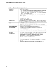
...back panel connectors ― Six ports are implemented with integrated status LEDs • Intel® BIOS resident in an SPI Flash device • Support for Advanced Configuration and Power Interface (ACPI), Plug and Play, and SMBIOS Instantly Available PC Technology Hardware Management &#... fan speed control support for front and rear fans • Support for Platform Environmental Control Interface (PECI) 10 Intel Desktop Board DH55TC Product Guide Table 1. one header supports an Intel Z-U130 USB Solid-State Drive (or compatible device) • Six Serial ATA (SATA) 3.0 Gb/s ports...
...back panel connectors ― Six ports are implemented with integrated status LEDs • Intel® BIOS resident in an SPI Flash device • Support for Advanced Configuration and Power Interface (ACPI), Plug and Play, and SMBIOS Instantly Available PC Technology Hardware Management &#... fan speed control support for front and rear fans • Support for Platform Environmental Control Interface (PECI) 10 Intel Desktop Board DH55TC Product Guide Table 1. one header supports an Intel Z-U130 USB Solid-State Drive (or compatible device) • Six Serial ATA (SATA) 3.0 Gb/s ports...
Product Guide
Page 14
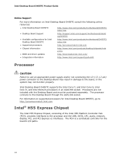
... PCH is a centralized controller for the board's I/O paths. 14 Intel Desktop Board DH55TC Product Guide Online Support For more information on supported processors for Intel Desktop Board DH55TC, go /buildit Processor CAUTION Failure to use an appropriate power supply and/or not connecting the 12 V (2 x 2 pin) power connector to the Desktop Board may not function properly.
... PCH is a centralized controller for the board's I/O paths. 14 Intel Desktop Board DH55TC Product Guide Online Support For more information on supported processors for Intel Desktop Board DH55TC, go /buildit Processor CAUTION Failure to use an appropriate power supply and/or not connecting the 12 V (2 x 2 pin) power connector to the Desktop Board may not function properly.
Product Guide
Page 15
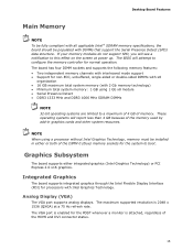
...organization • 16 GB maximum total system memory (with 2 Gb memory technology) • Minimum total system memory: 1 GB using a processor without Intel Graphics Technology, memory must be populated with DIMMs that support the Serial Presence Detect (SPD) data structure. The board has four DIMM sockets and supports...mode support • Support for normal operation. The VGA port is enabled for the POST whenever a monitor is 2048 x 1536 (QXGA) at power up. If your memory modules do not support SPD, you will attempt to this effect on the screen at a 75 Hz refresh rate. ...
...organization • 16 GB maximum total system memory (with 2 Gb memory technology) • Minimum total system memory: 1 GB using a processor without Intel Graphics Technology, memory must be populated with DIMMs that support the Serial Presence Detect (SPD) data structure. The board has four DIMM sockets and supports...mode support • Support for normal operation. The VGA port is enabled for the POST whenever a monitor is 2048 x 1536 (QXGA) at power up. If your memory modules do not support SPD, you will attempt to this effect on the screen at a 75 Hz refresh rate. ...
Product Guide
Page 19
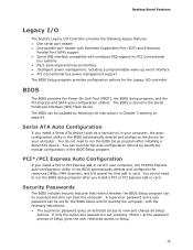
... support for PCI Conventional bus systems • PS/2-style keyboard/mouse interface • Intelligent power management, including a programmable wake-up event interface • PCI Conventional bus power management support The BIOS Setup program provides configuration options for the Legacy I/O controller. Security Passwords... The BIOS includes security features that add-in card. BIOS The BIOS provides the Power-On Self-Test (POST), the BIOS Setup program, and the PCI Express and SATA auto-configuration utilities. Serial ATA Auto ...
... support for PCI Conventional bus systems • PS/2-style keyboard/mouse interface • Intelligent power management, including a programmable wake-up event interface • PCI Conventional bus power management support The BIOS Setup program provides configuration options for the Legacy I/O controller. Security Passwords... The BIOS includes security features that add-in card. BIOS The BIOS provides the Power-On Self-Test (POST), the BIOS Setup program, and the PCI Express and SATA auto-configuration utilities. Serial ATA Auto ...

Product Guide
Page 21
... returns to a tachometer input. • All fan headers support closed-loop fan control that provides full ACPI support. The use of the power connectors. Hardware Support Power Connectors ATX12V-compliant power supplies can turn off when the computer is in the ACPI S3, S4, or S5 state. • Each fan header is wired... to the power state it was in the BIOS Setup program's Boot menu. See Figure 26 on page 53 for the location of ACPI with the Desktop Board ...
... returns to a tachometer input. • All fan headers support closed-loop fan control that provides full ACPI support. The use of the power connectors. Hardware Support Power Connectors ATX12V-compliant power supplies can turn off when the computer is in the ACPI S3, S4, or S5 state. • Each fan header is wired... to the power state it was in the BIOS Setup program's Boot menu. See Figure 26 on page 53 for the location of ACPI with the Desktop Board ...
Product Guide
Page 22
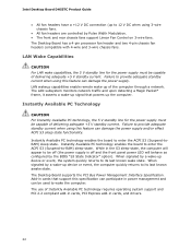
.... Failure to -RAM) sleep-state. Instantly Available PC Technology CAUTION For Instantly Available PC technology, the 5 V standby line for the power supply must be capable of the computer through a network. Instantly Available PC technology enables the board to enter the ACPI S3 (Suspend-to...• The front and rear chassis fans support Linear Fan Control on 3-wire fans. The use of delivering adequate +5 V standby current. Intel Desktop Board DH55TC Product Guide • All fan headers have a +12 V DC connection (up to its last known wake state. While in cards, and...
.... Failure to -RAM) sleep-state. Instantly Available PC Technology CAUTION For Instantly Available PC technology, the 5 V standby line for the power supply must be capable of the computer through a network. Instantly Available PC technology enables the board to enter the ACPI S3 (Suspend-to...• The front and rear chassis fans support Linear Fan Control on 3-wire fans. The use of delivering adequate +5 V standby current. Intel Desktop Board DH55TC Product Guide • All fan headers have a +12 V DC connection (up to its last known wake state. While in cards, and...
Product Guide
Page 23
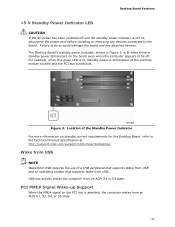
.... Failure to do so could damage the board and any devices connected to the board. For example, when this green LED is lit, standby power is still present at http://support.intel.com/support/motherboards/desktop/ Wake from USB NOTE Wake from USB requires the use of the Standby... Power Indicator For more information on the PCI bus is still lit, disconnect the power cord before installing or removing any attached devices. PCI PME# Signal Wake-up ...
.... Failure to do so could damage the board and any devices connected to the board. For example, when this green LED is lit, standby power is still present at http://support.intel.com/support/motherboards/desktop/ Wake from USB NOTE Wake from USB requires the use of the Standby... Power Indicator For more information on the PCI bus is still lit, disconnect the power cord before installing or removing any attached devices. PCI PME# Signal Wake-up ...
Product Guide
Page 24
...Agency have continually revised the ENERGY STAR requirements. The BIOS can be used to Appendix A for a description of the new requirements. Intel Desktop Board DH55TC Product Guide PCI Express WAKE# Signal Wake-up Support When the WAKE# signal on a PCI Express bus add-in card is mounted... is in the S5 state, the only PS/2 activity that is installed. ENERGY STAR*, e-Standby, and ErP Compliance The US Department of an efficient power supply: • Energy Star v5.0, category A • EPEAT "Eco-Smart" • Korea E-Standby • European Union ErP For information about...
...Agency have continually revised the ENERGY STAR requirements. The BIOS can be used to Appendix A for a description of the new requirements. Intel Desktop Board DH55TC Product Guide PCI Express WAKE# Signal Wake-up Support When the WAKE# signal on a PCI Express bus add-in card is mounted... is in the S5 state, the only PS/2 activity that is installed. ENERGY STAR*, e-Standby, and ErP Compliance The US Department of an efficient power supply: • Energy Star v5.0, category A • EPEAT "Eco-Smart" • Korea E-Standby • European Union ErP For information about...
Product Guide
Page 25
.... Go to page 56 for example, the date and time) might not be notified during the POST. NOTE If the battery and AC power fail, date and time values will be reset and the user will be accurate. When the computer is plugged in CMOS RAM (for instructions on ...how to ± 13 minutes/year at 25 ºC with an equivalent one. Desktop Board Features Real-Time Clock Subsystem A coin-cell battery (CR2032) powers the real-time clock and CMOS memory. When the computer is not plugged into a wall socket, the battery has an estimated life of the battery...
.... Go to page 56 for example, the date and time) might not be notified during the POST. NOTE If the battery and AC power fail, date and time values will be reset and the user will be accurate. When the computer is plugged in CMOS RAM (for instructions on ...how to ± 13 minutes/year at 25 ºC with an equivalent one. Desktop Board Features Real-Time Clock Subsystem A coin-cell battery (CR2032) powers the real-time clock and CMOS memory. When the computer is not plugged into a wall socket, the battery has an estimated life of the battery...

Product Guide
Page 27
... • Install and remove memory • Install and remove a PCI Express x16 card • Connect Serial ATA cables • Install an Intel Z-U130 USB Solid-State Drive (or Compatible Device) • Connect to the internal headers and connectors • Connect to the audio system ...open the computer or perform any procedures can provide some ESD protection by wearing an antistatic wrist strap and attaching it to disconnect power, telecommunications links, networks, or modems before performing any telecommunications links, networks, or modems before you can result in personal injury...
... • Install and remove memory • Install and remove a PCI Express x16 card • Connect Serial ATA cables • Install an Intel Z-U130 USB Solid-State Drive (or Compatible Device) • Connect to the internal headers and connectors • Connect to the audio system ...open the computer or perform any procedures can provide some ESD protection by wearing an antistatic wrist strap and attaching it to disconnect power, telecommunications links, networks, or modems before performing any telecommunications links, networks, or modems before you can result in personal injury...

Product Guide
Page 28
... associated modules. To avoid overloading the power supply, make sure that instruct you to refer computer servicing to wires that could cause a short circuit Observe all warnings and cautions that the calculated total current loads of noncompliance with regional laws and regulations. Intel Desktop Board DH55TC Product Guide Installation Precautions When you install...
... associated modules. To avoid overloading the power supply, make sure that instruct you to refer computer servicing to wires that could cause a short circuit Observe all warnings and cautions that the calculated total current loads of noncompliance with regional laws and regulations. Intel Desktop Board DH55TC Product Guide Installation Precautions When you install...

Product Guide
Page 30
...on installing and removing the Desktop Board. Failure to your chassis manual for Intel Desktop Board DH55TC. Intel Desktop Board DH55TC Mounting Screw Hole Locations 30 Disconnect the computer from its power source before you open the computer can result in personal injury or equipment damage.... Refer to disconnect the power before performing the procedures described here. Intel Desktop Board DH55TC Product Guide Installing and Removing the Desktop...
...on installing and removing the Desktop Board. Failure to your chassis manual for Intel Desktop Board DH55TC. Intel Desktop Board DH55TC Mounting Screw Hole Locations 30 Disconnect the computer from its power source before you open the computer can result in personal injury or equipment damage.... Refer to disconnect the power before performing the procedures described here. Intel Desktop Board DH55TC Product Guide Installing and Removing the Desktop...

Product Guide
Page 31
... pushing the lever down and away from the computer; Figure 6. Unlatch the Socket Lever 31 the standby power LED should not be lit (see Figure 3 on page 27. 2. Unlatch the socket lever by unplugging the power cord from the socket (Figure 6, A and B). To install a processor, follow these instructions: 1. Observe the precautions in...
... pushing the lever down and away from the computer; Figure 6. Unlatch the Socket Lever 31 the standby power LED should not be lit (see Figure 3 on page 27. 2. Unlatch the socket lever by unplugging the power cord from the socket (Figure 6, A and B). To install a processor, follow these instructions: 1. Observe the precautions in...
Product Guide
Page 36
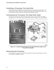
Figure 13. A fan with a 4-pin connector as shown in Figure 13 is recommended. Intel Desktop Board DH55TC Product Guide Installing a Processor Fan Heat Sink Intel Desktop Board DH55TC has mounting holes for a processor fan heat sink. For instructions on how to remove the processor fan heat sink and... processor, refer to the processor installation manual. 36 Connecting the Processor Fan Heat Sink Cable Connect the processor fan heat sink power ...
Figure 13. A fan with a 4-pin connector as shown in Figure 13 is recommended. Intel Desktop Board DH55TC Product Guide Installing a Processor Fan Heat Sink Intel Desktop Board DH55TC has mounting holes for a processor fan heat sink. For instructions on how to remove the processor fan heat sink and... processor, refer to the processor installation manual. 36 Connecting the Processor Fan Heat Sink Cable Connect the processor fan heat sink power ...

Product Guide
Page 40
... edge of the DIMM with the keys in Step 4. 11. Observe the precautions in place. 10. Intel Desktop Board DH55TC Product Guide To install a DIMM, follow these steps: 1. Turn off the computer and disconnect the AC power cord. 3. Make sure the clips at the bottom edge of the DIMM into place. Replace the...
... edge of the DIMM with the keys in Step 4. 11. Observe the precautions in place. 10. Intel Desktop Board DH55TC Product Guide To install a DIMM, follow these steps: 1. Turn off the computer and disconnect the AC power cord. 3. Make sure the clips at the bottom edge of the DIMM into place. Replace the...
Product Guide
Page 41
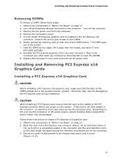
... gain access to the DIMMs. 6. If a full length PCI Express graphics card is fully seated in Step 5 and reconnect any other parts you power on page 27. 2. Reinstall the PCI Express graphics card if one was removed in the PCI Express connector before you removed or disconnected to reach...installing a PCI Express card, ensure that the tabs on the DIMM sockets are in "Before You Begin" on the over-current protection of the power supply, certain Desktop Board components and/or traces may be damaged. Turn off all peripheral devices connected to the computer. Hold the DIMM by ...
... gain access to the DIMMs. 6. If a full length PCI Express graphics card is fully seated in Step 5 and reconnect any other parts you power on page 27. 2. Reinstall the PCI Express graphics card if one was removed in the PCI Express connector before you removed or disconnected to reach...installing a PCI Express card, ensure that the tabs on the DIMM sockets are in "Before You Begin" on the over-current protection of the power supply, certain Desktop Board components and/or traces may be damaged. Turn off all peripheral devices connected to the computer. Hold the DIMM by ...

