

Product Guide
Page 5
Contents 1 Desktop Board Features Supported Operating Systems 10 Desktop Board Components 11 Processor ...13 Main Memory ...13 Intel® G965 Express Chipset 14 Intel G965 Graphics Subsystem 15 Onboard Audio Subsystem 16 Input/Output (I/O) Controller 17 LAN Subsystem 17 LAN Subsystem Software 17...Battery ...25 Real-Time Clock 25 2 Installing and Replacing Desktop Board Components Before You Begin 27 Installation Precautions 28 Prevent Power Supply Overload 28 Observe Safety and Regulatory Requirements 28 Installing the I/O Shield 29 Installing and Removing the Desktop Board 30 v
Contents 1 Desktop Board Features Supported Operating Systems 10 Desktop Board Components 11 Processor ...13 Main Memory ...13 Intel® G965 Express Chipset 14 Intel G965 Graphics Subsystem 15 Onboard Audio Subsystem 16 Input/Output (I/O) Controller 17 LAN Subsystem 17 LAN Subsystem Software 17...Battery ...25 Real-Time Clock 25 2 Installing and Replacing Desktop Board Components Before You Begin 27 Installation Precautions 28 Prevent Power Supply Overload 28 Observe Safety and Regulatory Requirements 28 Installing the I/O Shield 29 Installing and Removing the Desktop Board 30 v
Product Guide
Page 6
Intel Desktop Board DG965WH Product Guide Installing and Removing a Processor 31 Installing a Processor 31 Installing ...the Serial ATA (SATA) Cable 43 Connecting to Internal Headers 44 Installing a Front Panel Audio Solution for Intel® High Definition Audio 45 Connecting to the USB 2.0 Headers 46 Connecting to the Front Panel Header 46 ... Fan Cables 49 Connecting Power Cables 50 Other Connectors and Headers 51 Setting the BIOS Configuration Jumper 52 Clearing Passwords 53 Back Panel Connectors 54 3 Updating the BIOS Updating the BIOS with the Intel® Express BIOS Update...
Intel Desktop Board DG965WH Product Guide Installing and Removing a Processor 31 Installing a Processor 31 Installing ...the Serial ATA (SATA) Cable 43 Connecting to Internal Headers 44 Installing a Front Panel Audio Solution for Intel® High Definition Audio 45 Connecting to the USB 2.0 Headers 46 Connecting to the Front Panel Header 46 ... Fan Cables 49 Connecting Power Cables 50 Other Connectors and Headers 51 Setting the BIOS Configuration Jumper 52 Clearing Passwords 53 Back Panel Connectors 54 3 Updating the BIOS Updating the BIOS with the Intel® Express BIOS Update...
Product Guide
Page 7
...(Intel® QRTD) Overview...69 Intel Quick Resume Technology Power Modes 69 Installation and Configuration 70 A Error Messages and Indicators BIOS Beep Codes 73 BIOS Error Messages 73 B Regulatory Compliance Safety Regulations 75 Place Battery Marking 75 European Union Declaration of Other Connectors and Headers 51 27. Desktop Board DG965WH ...LEDs 18 3. Installing a PCI Express x16 Card 40 19. Install the Processor 33 11. Connecting the Serial ATA Cable 43 22. Connecting Power Supply Cables 50 26. Desktop Board DG965WH Mounting Screw Hole Locations 30 6.
...(Intel® QRTD) Overview...69 Intel Quick Resume Technology Power Modes 69 Installation and Configuration 70 A Error Messages and Indicators BIOS Beep Codes 73 BIOS Error Messages 73 B Regulatory Compliance Safety Regulations 75 Place Battery Marking 75 European Union Declaration of Other Connectors and Headers 51 27. Desktop Board DG965WH ...LEDs 18 3. Installing a PCI Express x16 Card 40 19. Install the Processor 33 11. Connecting the Serial ATA Cable 43 22. Connecting Power Supply Cables 50 26. Desktop Board DG965WH Mounting Screw Hole Locations 30 6.
Product Guide
Page 8
... Front Panel Power LED Header 47 9. Serial Port Header Signal Names 47 11. BIOS Error Messages 73 15. USB 2.0 Header Signal Names 46 7. Beep Codes 73 14. Lead-Free Board Markings 80 17. EMC Regulations 81 18. Original SATA Port Mapping for Intel High Definition ... Header Signal Names 47 10. Jumper Settings for Desktop Board DG965WH After RAID is Enabled 66 Tables 1. Safety Regulations 75 16. AC '97 Audio Header Signal Names 45 6. Desktop Board DG965WH Components 12 3. Intel Desktop Board DG965WH Product Guide 30. SATA Port Mapping for the BIOS Setup...
... Front Panel Power LED Header 47 9. Serial Port Header Signal Names 47 11. BIOS Error Messages 73 15. USB 2.0 Header Signal Names 46 7. Beep Codes 73 14. Lead-Free Board Markings 80 17. EMC Regulations 81 18. Original SATA Port Mapping for Intel High Definition ... Header Signal Names 47 10. Jumper Settings for Desktop Board DG965WH After RAID is Enabled 66 Tables 1. Safety Regulations 75 16. AC '97 Audio Header Signal Names 45 6. Desktop Board DG965WH Components 12 3. Intel Desktop Board DG965WH Product Guide 30. SATA Port Mapping for the BIOS Setup...

Product Guide
Page 10
... for extensible firmware interface • 8 Mbit symmetrical flash memory • Support for SMBIOS • Intel® Express BIOS Update Power Management • Support for Advanced Configuration and Power Interface (ACPI) • Suspend to RAM (STR) • Wake on USB, PCI Express, PS... sensing • Voltage sensing to detect out of range values • Intel® Quiet System Technology (Intel® QST) fan speed control Related Links: For more information about Desktop Board DG965WH, including the Technical Product Specification (TPS), BIOS updates, and device drivers,...
... for extensible firmware interface • 8 Mbit symmetrical flash memory • Support for SMBIOS • Intel® Express BIOS Update Power Management • Support for Advanced Configuration and Power Interface (ACPI) • Suspend to RAM (STR) • Wake on USB, PCI Express, PS... sensing • Voltage sensing to detect out of range values • Intel® Quiet System Technology (Intel® QST) fan speed control Related Links: For more information about Desktop Board DG965WH, including the Technical Product Specification (TPS), BIOS updates, and device drivers,...
Product Guide
Page 12
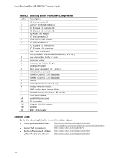
...V processor core voltage connector (2 x 2 pin ) Rear chassis fan header (3-pin) Processor socket Processor fan header (4-pin) Serial port header Main power connector (2 x 12 pin) Diskette drive connector DIMM 0, Channel A and B sockets DIMM 1, Channel A and B sockets Battery Front chassis fan ...more information about: • Desktop Board DG965WH http://www.intel.com/design/motherbd http://support.intel.com/support/motherboards/desktop • Supported processors http://www.intel.com/go/findCPU • Audio software and utilities http://www.intel.com/design/motherbd • LAN software...
...V processor core voltage connector (2 x 2 pin ) Rear chassis fan header (3-pin) Processor socket Processor fan header (4-pin) Serial port header Main power connector (2 x 12 pin) Diskette drive connector DIMM 0, Channel A and B sockets DIMM 1, Channel A and B sockets Battery Front chassis fan ...more information about: • Desktop Board DG965WH http://www.intel.com/design/motherbd http://support.intel.com/support/motherboards/desktop • Supported processors http://www.intel.com/go/findCPU • Audio software and utilities http://www.intel.com/design/motherbd • LAN software...

Product Guide
Page 13
... to the desktop board may not function properly. The processor connects to configure the memory controller for Desktop Board DG965WH is located on the web at power up. If your memory modules do not support SPD, you will attempt to the desktop board through the LGA775 socket. The BIOS will see.../go/findCPU Related Links: Go to the board or the system may result in the LGA775 package. Desktop Board DG965WH supports an Intel processor in damage to the following links or pages for : ― Unbuffered, non-registered single or double-sided DIMMs ― Non-ECC DDR2 memory ...
... to the desktop board may not function properly. The processor connects to configure the memory controller for Desktop Board DG965WH is located on the web at power up. If your memory modules do not support SPD, you will attempt to the desktop board through the LGA775 socket. The BIOS will see.../go/findCPU Related Links: Go to the board or the system may result in the LGA775 package. Desktop Board DG965WH supports an Intel processor in damage to the following links or pages for : ― Unbuffered, non-registered single or double-sided DIMMs ― Non-ECC DDR2 memory ...

Product Guide
Page 17
...one 1.2 MB or 1.44 MB diskette drive • Intelligent power management, including a programmable wake up event interface • PCI power management support LAN Subsystem The LAN subsystem consists of the following: • Intel 82566DC Gigabit Network Connection • RJ-45 connector with status ...indicator LEDs LAN Subsystem Software For LAN software and drivers, refer to the DG965WH link on Intel's World Wide...
...one 1.2 MB or 1.44 MB diskette drive • Intelligent power management, including a programmable wake up event interface • PCI power management support LAN Subsystem The LAN subsystem consists of the following: • Intel 82566DC Gigabit Network Connection • RJ-45 connector with status ...indicator LEDs LAN Subsystem Software For LAN software and drivers, refer to the DG965WH link on Intel's World Wide...

Product Guide
Page 18
Table 3. LAN Connector LEDs Table 3 describes the LED states when the board is powered up and the LAN subsystem is occurring 10 Mb/s data rate 100 Mb/s data rate 1000 Mb/s data rate 18 LAN Connector LED States LED A B ... N/A Green Yellow LED State Off On Blinking Off On On Indicates LAN link is not established LAN link is established LAN activity is operating. Intel Desktop Board DG965WH Product Guide RJ-45 LAN Connector LEDs Two LEDs are built into the RJ-45 LAN connector located on the back panel (see Figure...
Table 3. LAN Connector LEDs Table 3 describes the LED states when the board is powered up and the LAN subsystem is occurring 10 Mb/s data rate 100 Mb/s data rate 1000 Mb/s data rate 18 LAN Connector LED States LED A B ... N/A Green Yellow LED State Off On Blinking Off On On Indicates LAN link is not established LAN link is established LAN activity is operating. Intel Desktop Board DG965WH Product Guide RJ-45 LAN Connector LEDs Two LEDs are built into the RJ-45 LAN connector located on the back panel (see Figure...
Product Guide
Page 20
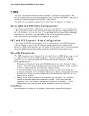
Intel Desktop Board DG965WH Product Guide BIOS The BIOS provides the Power-On Self-Test (POST), the BIOS Setup program, the PCI/PCI Express and IDE auto-configuration utilities, and the video BIOS. The BIOS can be ...
Intel Desktop Board DG965WH Product Guide BIOS The BIOS provides the Power-On Self-Test (POST), the BIOS Setup program, the PCI/PCI Express and IDE auto-configuration utilities, and the video BIOS. The BIOS can be ...

Product Guide
Page 21
... features of the hardware monitoring and fan speed control include: • Monitoring of power supply voltages to detect levels above and below acceptable values • Intel Quiet System Technology, delivering acoustically-optimized thermal management NOTE Memory must be compatible with ... specification. Desktop Board Features Hardware Management Features The hardware management features of Desktop Board DG965WH enable the board to be installed in the Channel A, DIMM 0 socket to enable Intel® Quiet System Technology. • Fan speed controllers and sensors integrated into the...
... features of the hardware monitoring and fan speed control include: • Monitoring of power supply voltages to detect levels above and below acceptable values • Intel Quiet System Technology, delivering acoustically-optimized thermal management NOTE Memory must be compatible with ... specification. Desktop Board Features Hardware Management Features The hardware management features of Desktop Board DG965WH enable the board to be installed in the Channel A, DIMM 0 socket to enable Intel® Quiet System Technology. • Fan speed controllers and sensors integrated into the...

Product Guide
Page 22
... input of the hardware monitoring and control device • All fan headers support closed-loop fan control that provides full ACPI support. Power Connectors ATX12V-compliant power supplies can adjust the fan speed or switch the fan on or off as follows: • The fans are on when the... S3, S4, or S5 state. • Each fan header is implemented at several levels, including: • Software support through system control. Intel Desktop Board DG965WH Product Guide Power Management Features Power management is wired to the power state it was in the BIOS Setup program's Boot menu.
... input of the hardware monitoring and control device • All fan headers support closed-loop fan control that provides full ACPI support. Power Connectors ATX12V-compliant power supplies can adjust the fan speed or switch the fan on or off as follows: • The fans are on when the... S3, S4, or S5 state. • Each fan header is implemented at several levels, including: • Software support through system control. Intel Desktop Board DG965WH Product Guide Power Management Features Power management is wired to the power state it was in the BIOS Setup program's Boot menu.
Product Guide
Page 23
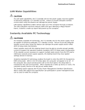
... turning amber. Add-in the S3 sleep state, the computer will appear to provide adequate standby current when using this feature can damage the power supply and/or effect ACPI S3 sleep state functionality. The LAN subsystem monitors network traffic and upon detecting a Magic Packet* frame, it asserts... the computer. 23 If the standby current necessary to provide adequate standby current when using this feature can damage the power supply. If the computer has a dual-colored power LED on the front panel, the sleep state is indicated by a wake-up signal that support this desktop board...
... turning amber. Add-in the S3 sleep state, the computer will appear to provide adequate standby current when using this feature can damage the power supply and/or effect ACPI S3 sleep state functionality. The LAN subsystem monitors network traffic and upon detecting a Magic Packet* frame, it asserts... the computer. 23 If the standby current necessary to provide adequate standby current when using this feature can damage the power supply. If the computer has a dual-colored power LED on the front panel, the sleep state is indicated by a wake-up signal that support this desktop board...

Product Guide
Page 24
Intel Desktop Board DG965WH Product Guide +5 V Standby Power Indicator LED CAUTION If the AC power has been switched off . Failure to the board. The method used depends on the type of Resume on Ring can be summarized as follows: • Resumes operation from the left-hand menu: http://support.intel....com/support/motherboards/desktop/ Resume on Ring Resume on Ring enables telephony devices to access the computer when it is in Figure 3, is lit when there is standby power still present on standby current requirements for the desktop...
Intel Desktop Board DG965WH Product Guide +5 V Standby Power Indicator LED CAUTION If the AC power has been switched off . Failure to the board. The method used depends on the type of Resume on Ring can be summarized as follows: • Resumes operation from the left-hand menu: http://support.intel....com/support/motherboards/desktop/ Resume on Ring Resume on Ring enables telephony devices to access the computer when it is in Figure 3, is lit when there is standby power still present on standby current requirements for the desktop...

Product Guide
Page 25
... is asserted, the computer wakes from an ACPI S2, S3, S4, or S5 state. The speaker provides audible error code (beep code) information during the Power-On Self-Test (POST). Battery A battery on the desktop board keeps the clock current when the computer is turned off . 25 The battery on the...
... is asserted, the computer wakes from an ACPI S2, S3, S4, or S5 state. The speaker provides audible error code (beep code) information during the Power-On Self-Test (POST). Battery A battery on the desktop board keeps the clock current when the computer is turned off . 25 The battery on the...

Product Guide
Page 27
...Serial ATA cables • Connect to the internal headers • Connect the flexible audio system • Connect the chassis fan and power cables • Set the BIOS configuration jumper • Clear passwords • Replace the battery Before You Begin CAUTIONS The procedures in ...computers and with the safety practices and regulatory compliance required for using an antistatic wrist strap and a conductive foam pad. Failure to disconnect power, telecommunications links, networks, or modems before you begin: • Always follow the steps in each procedure in the correct order. •...
...Serial ATA cables • Connect to the internal headers • Connect the flexible audio system • Connect the chassis fan and power cables • Set the BIOS configuration jumper • Clear passwords • Replace the battery Before You Begin CAUTIONS The procedures in ...computers and with the safety practices and regulatory compliance required for using an antistatic wrist strap and a conductive foam pad. Failure to disconnect power, telecommunications links, networks, or modems before you begin: • Always follow the steps in each procedure in the correct order. •...

Product Guide
Page 28
...you increase safety risk and the possibility of noncompliance with the chassis and associated modules. Intel Desktop Board DG965WH Product Guide Installation Precautions When you install and test the Intel desktop board, observe all warnings and cautions that instruct you to refer computer servicing ...to qualified technical personnel. To avoid overloading the power supply, make sure that your computer meets ...
...you increase safety risk and the possibility of noncompliance with the chassis and associated modules. Intel Desktop Board DG965WH Product Guide Installation Precautions When you install and test the Intel desktop board, observe all warnings and cautions that instruct you to refer computer servicing ...to qualified technical personnel. To avoid overloading the power supply, make sure that your computer meets ...

Product Guide
Page 30
... Screw Hole Locations 30 Figure 5. Failure to your chassis manual for Desktop Board DG965WH. Disconnect the computer from its power source before you open the computer can result in personal injury or equipment damage. Intel Desktop Board DG965WH Product Guide Installing and Removing the Desktop Board CAUTION Only qualified technical personnel should do this...
... Screw Hole Locations 30 Figure 5. Failure to your chassis manual for Desktop Board DG965WH. Disconnect the computer from its power source before you open the computer can result in personal injury or equipment damage. Intel Desktop Board DG965WH Product Guide Installing and Removing the Desktop Board CAUTION Only qualified technical personnel should do this...

Product Guide
Page 31
... should not be lit (see Figure 3 on page 27. 2. Open the socket lever by unplugging the power cord from the socket (Figure 6, A and B). Lift Socket Lever 3. Lift the load plate (Figure 7, A). Do not touch the socket contacts (Figure 7, B). Figure 7. Lift ...the Load Plate 31 To install a processor, follow these instructions: 1. Installing a Processor CAUTION Before installing or removing the processor, make sure the AC power has been removed by pushing the lever down and away from the computer; Failure to install the processor on the desktop board are given below...
... should not be lit (see Figure 3 on page 27. 2. Open the socket lever by unplugging the power cord from the socket (Figure 6, A and B). Lift Socket Lever 3. Lift the load plate (Figure 7, A). Do not touch the socket contacts (Figure 7, B). Figure 7. Lift ...the Load Plate 31 To install a processor, follow these instructions: 1. Installing a Processor CAUTION Before installing or removing the processor, make sure the AC power has been removed by pushing the lever down and away from the computer; Failure to install the processor on the desktop board are given below...

Product Guide
Page 38
...the bottom edge of the DIMM until the retaining clips snap into the socket. 8. Replace the computer's cover and reconnect the AC power cord. 38 Intel Desktop Board DG965WH Product Guide NOTE Memory must be installed in place. 9. Figure 17. Installing a DIMM 4. When the DIMM is inserted, push... down on page 27. 2. To install a DIMM, follow these steps: 1. Turn off the computer and disconnect the AC power cord. 3. Holding the DIMM ...
...the bottom edge of the DIMM until the retaining clips snap into the socket. 8. Replace the computer's cover and reconnect the AC power cord. 38 Intel Desktop Board DG965WH Product Guide NOTE Memory must be installed in place. 9. Figure 17. Installing a DIMM 4. When the DIMM is inserted, push... down on page 27. 2. To install a DIMM, follow these steps: 1. Turn off the computer and disconnect the AC power cord. 3. Holding the DIMM ...

