
Product Guide
Page 3
... components 3 Updating the BIOS: instructions on how to update the BIOS 4 Configuring for RAID (Intel® Matrix Storage Technology): information about configuring your system for RAID 5 Intel® Quick Resume Technology Driver (Intel® QRTD): information about installing and configuring Intel Quick Resume Technology Driver A Error Messages and Indicators: information about BIOS error messages and beep codes B Regulatory Compliance: safety and EMC regulations and product certifications Conventions The following conventions are used in this Product Guide are evaluated...
... components 3 Updating the BIOS: instructions on how to update the BIOS 4 Configuring for RAID (Intel® Matrix Storage Technology): information about configuring your system for RAID 5 Intel® Quick Resume Technology Driver (Intel® QRTD): information about installing and configuring Intel Quick Resume Technology Driver A Error Messages and Indicators: information about BIOS error messages and beep codes B Regulatory Compliance: safety and EMC regulations and product certifications Conventions The following conventions are used in this Product Guide are evaluated...
Product Guide
Page 6
... the BIOS Configuration Jumper 52 Clearing Passwords 53 Back Panel Connectors 54 3 Updating the BIOS Updating the BIOS with the Intel® Express BIOS Update Utility 61 Updating the BIOS with the ISO Image BIOS Update File or the Iflash Memory Update Utility 62 Obtaining the BIOS Update File 62 Updating the BIOS with the ISO Image BIOS Update File 62 Updating the BIOS with Iflash 63 Recovering the BIOS 64 4 Configuring for RAID (Intel® Matrix Storage Technology) Configuring the BIOS for Intel Matrix Storage Technology 65 SATA Port Mapping 65 Creating Your RAID Set 66 Loading...
... the BIOS Configuration Jumper 52 Clearing Passwords 53 Back Panel Connectors 54 3 Updating the BIOS Updating the BIOS with the Intel® Express BIOS Update Utility 61 Updating the BIOS with the ISO Image BIOS Update File or the Iflash Memory Update Utility 62 Obtaining the BIOS Update File 62 Updating the BIOS with the ISO Image BIOS Update File 62 Updating the BIOS with Iflash 63 Recovering the BIOS 64 4 Configuring for RAID (Intel® Matrix Storage Technology) Configuring the BIOS for Intel Matrix Storage Technology 65 SATA Port Mapping 65 Creating Your RAID Set 66 Loading...
Product Guide
Page 7
... Connector LEDs 18 3. Dual Channel Memory Configuration Example 2 36 15. Installing a PCI Express x16 Card 40 19. Removing a PCI Express x16 Card 41 20. Connecting the Processor Fan Heat Sink Cable to the Processor Fan Header.......... 34 13. Internal Headers 44 23. Close the Load Plate 33 12. Dual Channel Memory Configuration Example 3 36 16. Use DDR2 DIMMs 37 17. Location of the BIOS Configuration Jumper Block 52 28. Install the Processor 33 11. Location of Standby Power Indicator 24 4. Removing the Battery 59 vii Location of Chassis Fan Headers...
... Connector LEDs 18 3. Dual Channel Memory Configuration Example 2 36 15. Installing a PCI Express x16 Card 40 19. Removing a PCI Express x16 Card 41 20. Connecting the Processor Fan Heat Sink Cable to the Processor Fan Header.......... 34 13. Internal Headers 44 23. Close the Load Plate 33 12. Dual Channel Memory Configuration Example 3 36 16. Use DDR2 DIMMs 37 17. Location of the BIOS Configuration Jumper Block 52 28. Install the Processor 33 11. Location of Standby Power Indicator 24 4. Removing the Battery 59 vii Location of Chassis Fan Headers...
Product Guide
Page 9
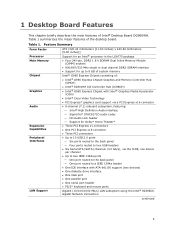
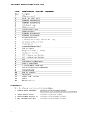
... panel ― Four ports routed to two USB headers • Six Serial ATA (SATA) channels (3.0 Gb/s), via a PCI Express x16 connector • 8-channel (7.1) onboard subsystem, featuring: ― Intel® High Definition Audio interface ― SigmaTel* STAC9271D audio codec ― HD Audio Link header ― Support for up to 8 GB of system memory Intel® G965 Express Chipset consisting of Intel® Desktop Board DG965WH. Table 1. 1 Desktop Board Features This chapter briefly describes the main features of : • Intel® G965 Express Chipset Graphics and Memory...
... panel ― Four ports routed to two USB headers • Six Serial ATA (SATA) channels (3.0 Gb/s), via a PCI Express x16 connector • 8-channel (7.1) onboard subsystem, featuring: ― Intel® High Definition Audio interface ― SigmaTel* STAC9271D audio codec ― HD Audio Link header ― Support for up to 8 GB of system memory Intel® G965 Express Chipset consisting of Intel® Desktop Board DG965WH. Table 1. 1 Desktop Board Features This chapter briefly describes the main features of : • Intel® G965 Express Chipset Graphics and Memory...
Product Guide
Page 12
... header PCI bus connector 1 PCI Express x1 connector 1 PCI Express x16 connector Back panel connectors 12 V processor core voltage connector (2 x 2 pin ) Rear chassis fan header (3-pin) Processor socket Processor fan header (4-pin) Serial port header Main power connector (2 x 12 pin) Diskette drive connector DIMM 0, Channel A and B sockets DIMM 1, Channel A and B sockets Battery Front chassis fan header (3-pin) Chassis intrusion header BIOS configuration jumper block Alternate front panel power LED header Front panel header Serial ATA connectors IDE connector Hi-speed USB 2.0 headers Speaker...
... header PCI bus connector 1 PCI Express x1 connector 1 PCI Express x16 connector Back panel connectors 12 V processor core voltage connector (2 x 2 pin ) Rear chassis fan header (3-pin) Processor socket Processor fan header (4-pin) Serial port header Main power connector (2 x 12 pin) Diskette drive connector DIMM 0, Channel A and B sockets DIMM 1, Channel A and B sockets Battery Front chassis fan header (3-pin) Chassis intrusion header BIOS configuration jumper block Alternate front panel power LED header Front panel header Serial ATA connectors IDE connector Hi-speed USB 2.0 headers Speaker...

Product Guide
Page 15
... memory is used or a PCI Express x16 add-in card is installed, the GMA X3000 graphics controller is disabled. Desktop Board Features Intel G965 Graphics Subsystem The Intel G965 Express Chipset contains two separate, mutually exclusive graphics options. Either the integrated GMA X3000 graphics controller is required in order for sharp image quality at high resolutions For more information on Intel Clear Video Technology, go to operate properly. 15 When a PCI Express x16 add-in card can be used...
... memory is used or a PCI Express x16 add-in card is installed, the GMA X3000 graphics controller is disabled. Desktop Board Features Intel G965 Graphics Subsystem The Intel G965 Express Chipset contains two separate, mutually exclusive graphics options. Either the integrated GMA X3000 graphics controller is required in order for sharp image quality at high resolutions For more information on Intel Clear Video Technology, go to operate properly. 15 When a PCI Express x16 add-in card can be used...
Product Guide
Page 20
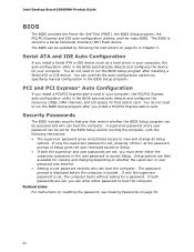
... computer. Intel Desktop Board DG965WH Product Guide BIOS The BIOS provides the Power-On Self-Test (POST), the BIOS Setup program, the PCI/PCI Express and IDE auto-configuration utilities, and the video BIOS. Serial ATA and IDE Auto Configuration If you install a PCI/PCI Express add-in card in a Serial Peripheral Interface (SPI) Flash device. You do not need to view and change all Setup options. A supervisor password and a user password can be set , you can boot the computer. PCI and PCI Express* Auto Configuration If you install a Serial ATA or IDE device (such as a hard drive) in...
... computer. Intel Desktop Board DG965WH Product Guide BIOS The BIOS provides the Power-On Self-Test (POST), the BIOS Setup program, the PCI/PCI Express and IDE auto-configuration utilities, and the video BIOS. Serial ATA and IDE Auto Configuration If you install a PCI/PCI Express add-in card in a Serial Peripheral Interface (SPI) Flash device. You do not need to view and change all Setup options. A supervisor password and a user password can be set , you can boot the computer. PCI and PCI Express* Auto Configuration If you install a Serial ATA or IDE device (such as a hard drive) in...

Product Guide
Page 22
... power through the Advanced Configuration and Power Interface (ACPI) • Hardware support: ― Power connectors ― Fan headers ― LAN wake capabilities ― Instantly Available PC technology (Suspend to a tachometer input of a computer. The use of the power connectors. When an ACPI-enabled computer receives the correct command, the power supply removes all non-standby voltages. The desktop board has two power connectors. Intel Desktop Board DG965WH Product Guide Power Management Features Power management is wired to RAM) ― +5 V standby power indicator LED...
... power through the Advanced Configuration and Power Interface (ACPI) • Hardware support: ― Power connectors ― Fan headers ― LAN wake capabilities ― Instantly Available PC technology (Suspend to a tachometer input of a computer. The use of the power connectors. When an ACPI-enabled computer receives the correct command, the power supply removes all non-standby voltages. The desktop board has two power connectors. Intel Desktop Board DG965WH Product Guide Power Management Features Power management is wired to RAM) ― +5 V standby power indicator LED...
Product Guide
Page 53
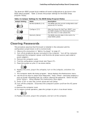
.... 2. Replace the cover, plug in the computer and the configuration jumper block is installed in the computer, turn on pins 2-3 as shown below . 6. Turn off all board configurations to be done in the event of a failed BIOS update. Find the configuration jumper block (see Figure 27). 5. Setup displays the Maintenance menu. 8. Clearing Passwords This procedure assumes that you confirm clearing the password. Jumper Settings for the BIOS Setup Program Modes Jumper Setting Mode Normal (default) (1-2) Description The BIOS uses the current configuration and passwords...
.... 2. Replace the cover, plug in the computer and the configuration jumper block is installed in the computer, turn on pins 2-3 as shown below . 6. Turn off all board configurations to be done in the event of a failed BIOS update. Find the configuration jumper block (see Figure 27). 5. Setup displays the Maintenance menu. 8. Clearing Passwords This procedure assumes that you confirm clearing the password. Jumper Settings for the BIOS Setup Program Modes Jumper Setting Mode Normal (default) (1-2) Description The BIOS uses the current configuration and passwords...

Product Guide
Page 66
.... Select the strip size, if necessary, and press . 6. Intel Desktop Board DG965WH Product Guide Figure 31. In the Intel Matrix Storage Manager option ROM Main Menu, select option #1: Create RAID Volume. Use the arrow keys to be in the MAIN MENU. 66 Exit the Option ROM user interface by pressing or going to Create Volume. 8. Upon re-boot, you can then create a second RAID array on the screen: Press to enter the RAID Configuration Utility. 2. Finally, press to...
.... Select the strip size, if necessary, and press . 6. Intel Desktop Board DG965WH Product Guide Figure 31. In the Intel Matrix Storage Manager option ROM Main Menu, select option #1: Create RAID Volume. Use the arrow keys to be in the MAIN MENU. 66 Exit the Option ROM user interface by pressing or going to Create Volume. 8. Upon re-boot, you can then create a second RAID array on the screen: Press to enter the RAID Configuration Utility. 2. Finally, press to...

Product Guide
Page 67
...Windows installation CD. 2. Begin Windows Setup by booting from this section: "Configuring the BIOS for Intel Matrix Storage Technology" and "Loading the Intel Matrix Storage Technology RAID Drivers and Software". Setting Up a "RAID Ready" System The Intel Matrix Storage Technology Console software offers the flexibility to upgrade from the Internet at http://support.intel.com/support/motherboards/desktop/. When prompted, insert the diskette labeled Intel Matrix Storage Technology RAID Driver. At the beginning of Windows Setup, press to the system. Once additional SATA drives...
...Windows installation CD. 2. Begin Windows Setup by booting from this section: "Configuring the BIOS for Intel Matrix Storage Technology" and "Loading the Intel Matrix Storage Technology RAID Drivers and Software". Setting Up a "RAID Ready" System The Intel Matrix Storage Technology Console software offers the flexibility to upgrade from the Internet at http://support.intel.com/support/motherboards/desktop/. When prompted, insert the diskette labeled Intel Matrix Storage Technology RAID Driver. At the beginning of Windows Setup, press to the system. Once additional SATA drives...

Product Specification
Page 6
...70 3.3.2 PCI IDE Support 71 3.4 System Management BIOS (SMBIOS 71 3.5 Legacy USB Support 72 3.6 BIOS Updates 72 3.6.1 Language Support 73 3.6.2 Custom Splash Screen 73 3.7 BIOS Recovery 73 3.8 Boot Options 74 3.8.1 CD-ROM Boot 74 3.8.2 Network Boot 74 3.8.3 Booting Without Attached Devices 74 3.8.4 Changing the Default Boot Device During POST 74 3.9 Adjusting Boot Speed 75 3.9.1 Peripheral Selection and Configuration 75 3.9.2 BIOS Boot Optimizations 75 3.10 BIOS Security Features 76 4 Error Messages and Beep Codes 4.1 Speaker 77 4.2 BIOS Beep Codes 77 4.3 BIOS Error Messages...
...70 3.3.2 PCI IDE Support 71 3.4 System Management BIOS (SMBIOS 71 3.5 Legacy USB Support 72 3.6 BIOS Updates 72 3.6.1 Language Support 73 3.6.2 Custom Splash Screen 73 3.7 BIOS Recovery 73 3.8 Boot Options 74 3.8.1 CD-ROM Boot 74 3.8.2 Network Boot 74 3.8.3 Booting Without Attached Devices 74 3.8.4 Changing the Default Boot Device During POST 74 3.9 Adjusting Boot Speed 75 3.9.1 Peripheral Selection and Configuration 75 3.9.2 BIOS Boot Optimizations 75 3.10 BIOS Security Features 76 4 Error Messages and Beep Codes 4.1 Speaker 77 4.2 BIOS Beep Codes 77 4.3 BIOS Error Messages...

Product Specification
Page 7
... Dual Channel (Interleaved) Mode Configuration with Four DIMMs 20 7. Connection Diagram for IEEE 1394a Header 59 20. Connection Diagram for Front Panel Header 57 18. Manufacturing Options 11 3. Audio Jack Retasking Support 29 7. Board Components Shown in Figure 1 13 4. Connection Diagram for Boards with PS/2 Ports 62 23. I /O Shield Dimensions for Front Panel USB Headers 59 19. Dual Channel (Interleaved) Mode Configuration with Two DIMMs 19 5. Board Dimensions 61 22. Memory Operating Frequencies 17 6. Block Diagram 14 3. LAN Connector LED Locations...
... Dual Channel (Interleaved) Mode Configuration with Four DIMMs 20 7. Connection Diagram for IEEE 1394a Header 59 20. Connection Diagram for Front Panel Header 57 18. Manufacturing Options 11 3. Audio Jack Retasking Support 29 7. Board Components Shown in Figure 1 13 4. Connection Diagram for Boards with PS/2 Ports 62 23. I /O Shield Dimensions for Front Panel USB Headers 59 19. Dual Channel (Interleaved) Mode Configuration with Two DIMMs 19 5. Board Dimensions 61 22. Memory Operating Frequencies 17 6. Block Diagram 14 3. LAN Connector LED Locations...

Product Specification
Page 8
... Header 54 20. Front Panel Audio Header 54 21. Processor Core Power Connector 56 27. BIOS Setup Program Menu Bar 70 37. BIOS Setup Program Function Keys 70 38. Beep Codes 77 42. Chassis Intrusion Header 55 24. DC Loading Characteristics 64 33. Acceptable Drives/Media Types for a One-Color Power LED 58 30. Port 80h POST Code Ranges 78 44. Intel Desktop Board DG965WH Technical Product Specification 10. Interrupts 48 16. BIOS Error Messages 77 43. Front and Rear Chassis Fan Headers 55 25. Front Panel Header...
... Header 54 20. Front Panel Audio Header 54 21. Processor Core Power Connector 56 27. BIOS Setup Program Menu Bar 70 37. BIOS Setup Program Function Keys 70 38. Beep Codes 77 42. Chassis Intrusion Header 55 24. DC Loading Characteristics 64 33. Acceptable Drives/Media Types for a One-Color Power LED 58 30. Port 80h POST Code Ranges 78 44. Intel Desktop Board DG965WH Technical Product Specification 10. Interrupts 48 16. BIOS Error Messages 77 43. Front and Rear Chassis Fan Headers 55 25. Front Panel Header...

Product Specification
Page 16
Supported Memory Configurations DIMM Type SDRAM Technology Smallest usable DIMM (one x16 Single-...lists the supported DIMM configurations. This allows the BIOS to read the SPD data and program the chipset to correctly configure the memory settings, but performance and reliability may not function under the determined frequency. If non-SPD memory is required to fully enable both the onboard graphics and the manageability engine. Table 4. Intel Desktop Board DG965WH Technical Product Specification 1.4 System Memory The board has four DIMM sockets and support the following memory...
Supported Memory Configurations DIMM Type SDRAM Technology Smallest usable DIMM (one x16 Single-...lists the supported DIMM configurations. This allows the BIOS to read the SPD data and program the chipset to correctly configure the memory settings, but performance and reliability may not function under the determined frequency. If non-SPD memory is required to fully enable both the onboard graphics and the manageability engine. Table 4. Intel Desktop Board DG965WH Technical Product Specification 1.4 System Memory The board has four DIMM sockets and support the following memory...

Product Specification
Page 69
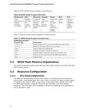
... 3.5 Legacy USB Support 72 3.6 BIOS Updates 72 3.7 BIOS Recovery 73 3.8 Boot Options 74 3.9 Adjusting Boot Speed 75 3.10 BIOS Security Features 76 3.1 Introduction The board uses an Intel BIOS that is stored in configure mode. The BIOS Setup program is in the Serial Peripheral Interface Flash Memory (SPI Flash) and can be updated using a disk-based program. Maintenance Main Advanced Security Power Boot Exit NOTE The maintenance menu is displayed only when the board is accessed by pressing the key after the Power-On Self-Test (POST) memory...
... 3.5 Legacy USB Support 72 3.6 BIOS Updates 72 3.7 BIOS Recovery 73 3.8 Boot Options 74 3.9 Adjusting Boot Speed 75 3.10 BIOS Security Features 76 3.1 Introduction The board uses an Intel BIOS that is stored in configure mode. The BIOS Setup program is in the Serial Peripheral Interface Flash Memory (SPI Flash) and can be updated using a disk-based program. Maintenance Main Advanced Security Power Boot Exit NOTE The maintenance menu is displayed only when the board is accessed by pressing the key after the Power-On Self-Test (POST) memory...
Product Specification
Page 70
BIOS Setup Program Menu Bar Maintenance Main Advanced Security Clears passwords and displays processor information Displays processor and memory configuretion Configures advanced features available through the chipset Sets passwords and security features Power Configures power management features and power supply controls Boot Selects boot options Exit Saves or discards changes to configure the system. BIOS Setup Program Function Keys BIOS Setup Program Function Key Description or or Selects a different menu screen (Moves the cursor left or right) Selects an item (Moves the ...
BIOS Setup Program Menu Bar Maintenance Main Advanced Security Clears passwords and displays processor information Displays processor and memory configuretion Configures advanced features available through the chipset Sets passwords and security features Power Configures power management features and power supply controls Boot Selects boot options Exit Saves or discards changes to configure the system. BIOS Setup Program Function Keys BIOS Setup Program Function Key Description or or Selects a different menu screen (Moves the cursor left or right) Selects an item (Moves the ...
Product Specification
Page 71
.... 71 The BIOS supports an SMBIOS table interface for accessing this support, an SMBIOS service-level application running on a non-Plug and Play operating system can override the auto-configuration options by specifying manual configuration in a managed network. Overview of BIOS Features 3.3.2 PCI IDE Support If you select Auto in the BIOS Setup program, the BIOS automatically sets up to PIO Mode 3 or 4, depending on the capability of the drive. The BIOS determines the...
.... 71 The BIOS supports an SMBIOS table interface for accessing this support, an SMBIOS service-level application running on a non-Plug and Play operating system can override the auto-configuration options by specifying manual configuration in a managed network. Overview of BIOS Features 3.3.2 PCI IDE Support If you select Auto in the BIOS Setup program, the BIOS automatically sets up to PIO Mode 3 or 4, depending on the capability of the drive. The BIOS determines the...

Product Specification
Page 79
... Hot Plug PCI controller initialization Reserved for PCI Bus USB 58 Resetting USB bus 59 Reserved for USB ATA/ATAPI/SATA 5A Resetting PATA/SATA bus and all devices 5B Reserved for ATA SMBus 5C Resetting SMBUS 5D Reserved for SMBUS Local Console 70 Resetting the VGA controller 71 Disabling the VGA controller 72 Enabling the VGA controller Remote Console 78 Resetting the console controller 79 Disabling the console controller 7A Enabling the console controller continued 79 Error Messages and Beep Codes Table 44...
... Hot Plug PCI controller initialization Reserved for PCI Bus USB 58 Resetting USB bus 59 Reserved for USB ATA/ATAPI/SATA 5A Resetting PATA/SATA bus and all devices 5B Reserved for ATA SMBus 5C Resetting SMBUS 5D Reserved for SMBUS Local Console 70 Resetting the VGA controller 71 Disabling the VGA controller 72 Enabling the VGA controller Remote Console 78 Resetting the console controller 79 Disabling the console controller 7A Enabling the console controller continued 79 Error Messages and Beep Codes Table 44...
Product Specification
Page 81
... password E9 Entering BIOS setup EB Calling Legacy Option ROMs Runtime Phase/EFI OS Boot F4 Entering Sleep state F5 Exiting Sleep state F8 EFI boot service ExitBootServices ( ) has been called F9 EFI runtime service SetVirtualAddressMap ( ) has been called FA EFI runtime service ResetSystem ( ) has been called PEIMs/Recovery 30 Crisis Recovery has initiated per User request 31 Crisis Recovery has initiated by software (corrupt flash) 34 Loading recovery capsule 35 Handing off control...
... password E9 Entering BIOS setup EB Calling Legacy Option ROMs Runtime Phase/EFI OS Boot F4 Entering Sleep state F5 Exiting Sleep state F8 EFI boot service ExitBootServices ( ) has been called F9 EFI runtime service SetVirtualAddressMap ( ) has been called FA EFI runtime service ResetSystem ( ) has been called PEIMs/Recovery 30 Crisis Recovery has initiated per User request 31 Crisis Recovery has initiated by software (corrupt flash) 34 Loading recovery capsule 35 Handing off control...


