
English Manual
Page 6
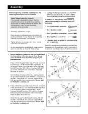
... 20 40 6 Before beginning, make sure all parts as shown in the assembly steps may be more convenient if you assemble the weight bench, make sure that the weight bench can be pre-assembled. Insert two M8 x 65mm Carriage Bolts (59) and two M10 x 65mm Carriage Bolts (40) up into ...the indicated holes in the position shown. Press a 50mm Square Outer Cap (17) onto each end of time, and by anyone. Assembly Before beginning assembly, ...
... 20 40 6 Before beginning, make sure all parts as shown in the assembly steps may be more convenient if you assemble the weight bench, make sure that the weight bench can be pre-assembled. Insert two M8 x 65mm Carriage Bolts (59) and two M10 x 65mm Carriage Bolts (40) up into ...the indicated holes in the position shown. Press a 50mm Square Outer Cap (17) onto each end of time, and by anyone. Assembly Before beginning assembly, ...
English Manual
Page 8
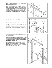
Press a 25mm Round Inner Cap (51) into the end of 6 the other Weight Storage Tube (21). Thread an M10 Nylon Locknut (11) onto each Bolt. Do ... Locknut (11) onto each Bolt. Have a second person hold the Middle Crossbar (8), insert two M10 x 70mm Bolts (46) through the bracket on the Middle Crossbar. 5. Press a 25mm Round Inner Cap (51) into the end of 5 a Weight Storage Tube (21). 2 While a second person holds the Middle Crossbar (8) in 7 the position shown...
Press a 25mm Round Inner Cap (51) into the end of 6 the other Weight Storage Tube (21). Thread an M10 Nylon Locknut (11) onto each Bolt. Do ... Locknut (11) onto each Bolt. Have a second person hold the Middle Crossbar (8), insert two M10 x 70mm Bolts (46) through the bracket on the Middle Crossbar. 5. Press a 25mm Round Inner Cap (51) into the end of 5 a Weight Storage Tube (21). 2 While a second person holds the Middle Crossbar (8) in 7 the position shown...

English Manual
Page 9
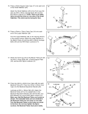
...Identify the Left Weight Glider (32) by the position of the handle and the Left Spotter Hook (65). Press a 38mm Bushing (29) into each end of 35 the Barbell (35). Round tube 29 32 50 29 ...not tighten the Nylon Locknut yet. 9 11 18 34 32 Handle 24 54 52 1 65 7 Hole 39 Press a 38mm Bushing (29) into each end of the Barbell (35). The Left Weight Glider must be turned...8 Locking Bar (34). Insert a Weight Guide (18) into each end of the Left Safety Spotter (24). Press a 25mm Bushing (48) into the Left Weight Glider, the Left Safety Spotter, and the hole in the Locking ...
...Identify the Left Weight Glider (32) by the position of the handle and the Left Spotter Hook (65). Press a 38mm Bushing (29) into each end of 35 the Barbell (35). Round tube 29 32 50 29 ...not tighten the Nylon Locknut yet. 9 11 18 34 32 Handle 24 54 52 1 65 7 Hole 39 Press a 38mm Bushing (29) into each end of the Barbell (35). The Left Weight Glider must be turned...8 Locking Bar (34). Insert a Weight Guide (18) into each end of the Left Safety Spotter (24). Press a 25mm Bushing (48) into the Left Weight Glider, the Left Safety Spotter, and the hole in the Locking ...
English Manual
Page 11
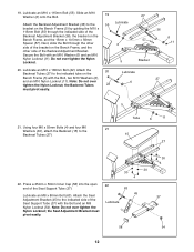
... 18. Holes 28 28 Welded Tube 36 11 28 6 11 28 Attach the Small Stabilizer (25) to the Bench Frame (5) with two M10 x 65mm Carriage Bolts (40) and two M10 Nylon Locknuts (11). Press two 20mm x 40mm Inner Caps (28) into the Backrest Adjustment Bracket (36). 18 Lubricate 27 22 6 Lubricate ... Bracket (36) with two M10 x 65mm Carriage Bolts (40) and two M10 Nylon Locknuts (11). 40 17 5 10 26 11 10 40 17. 15. Press a 50mm Square Outer Cap (17) onto each end of the Small Stabilizer (25). Note: There is in the Backrest Tubes but are closer to the...
... 18. Holes 28 28 Welded Tube 36 11 28 6 11 28 Attach the Small Stabilizer (25) to the Bench Frame (5) with two M10 x 65mm Carriage Bolts (40) and two M10 Nylon Locknuts (11). Press two 20mm x 40mm Inner Caps (28) into the Backrest Adjustment Bracket (36). 18 Lubricate 27 22 6 Lubricate ... Bracket (36) with two M10 x 65mm Carriage Bolts (40) and two M10 Nylon Locknuts (11). 40 17 5 10 26 11 10 40 17. 15. Press a 50mm Square Outer Cap (17) onto each end of the Small Stabilizer (25). Note: There is in the Backrest Tubes but are closer to the...
English Manual
Page 12
...the Seat Adjustment Bracket (45) to the indicated tube on the 20 Lubricate Bench Frame (5) with the Bolt, two M10 Washers (6), 27 and an M10 Nylon...the Backrest Tubes (27) to the indicated side of the bracket on the Bench Frame, and the 15mm x 10.5mm x 56mm Spacer (57). the ...M6 Washers (30), attach the Backrest (15) to the Lubricate 55 bracket on the Bench Frame (5) by guiding the M10 x 115mm Bolt (55) through the other 6 side...the indicated side of the Backrest Adjustment Bracket (36), the bracket on the Bench Frame, and the other side of the Seat Support Tube (37). 63...
...the Seat Adjustment Bracket (45) to the indicated tube on the 20 Lubricate Bench Frame (5) with the Bolt, two M10 Washers (6), 27 and an M10 Nylon...the Backrest Tubes (27) to the indicated side of the bracket on the Bench Frame, and the 15mm x 10.5mm x 56mm Spacer (57). the ...M6 Washers (30), attach the Backrest (15) to the Lubricate 55 bracket on the Bench Frame (5) by guiding the M10 x 115mm Bolt (55) through the other 6 side...the indicated side of the Backrest Adjustment Bracket (36), the bracket on the Bench Frame, and the other side of the Seat Support Tube (37). 63...