

Instruction Manual
Page 3
... 1- 6 s Front panel 1 s Rear panel 5 s Function display 6 2 CONNECTIONS 7- 10 s Mounting installation 7 s Required connections 8 s Antenna connection 9 s Grounding 9 s Tape recorder connections 10 s Transceive function 10 s Connecting to a PC 10 s Data demodulation terminal 10 3 FREQUENCY SETTING 11- 12 s Read me first 11 s Using the keypad 11 s Using the main dial 12 s Lock function 12 4 RECEIVE FUNCTIONS 13- 16 s Initial settings 13 s Mode selection 13 s Squelch function 14 s Functions for FM 14...
... 1- 6 s Front panel 1 s Rear panel 5 s Function display 6 2 CONNECTIONS 7- 10 s Mounting installation 7 s Required connections 8 s Antenna connection 9 s Grounding 9 s Tape recorder connections 10 s Transceive function 10 s Connecting to a PC 10 s Data demodulation terminal 10 3 FREQUENCY SETTING 11- 12 s Read me first 11 s Using the keypad 11 s Using the main dial 12 s Lock function 12 4 RECEIVE FUNCTIONS 13- 16 s Initial settings 13 s Mode selection 13 s Squelch function 14 s Functions for FM 14...
Instruction Manual
Page 4
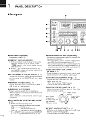
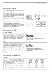
... to mute noise when receiving no receive audio comes from the speaker. • Stereo headphones can be connected, however, output is monaural. › MODE SWITCHES [WFM]/[FM]/[AM]/[SSB/CW] (p. 13) ¯ Push to select an operating mode. • The following keys toggle between "slow" and "fast." • When "fast" is used for recording. Connects to adjust the BFO frequency. (p. 15). œ NOISE BLANKER/AFC SWITCH [NB...
... to mute noise when receiving no receive audio comes from the speaker. • Stereo headphones can be connected, however, output is monaural. › MODE SWITCHES [WFM]/[FM]/[AM]/[SSB/CW] (p. 13) ¯ Push to select an operating mode. • The following keys toggle between "slow" and "fast." • When "fast" is used for recording. Connects to adjust the BFO frequency. (p. 15). œ NOISE BLANKER/AFC SWITCH [NB...
Instruction Manual
Page 5
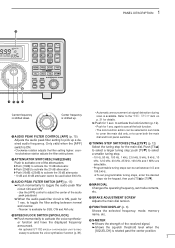
... selected frequency, mode, memory !5 SPEECH/LOCK SWITCH [SPCH/LOCK] name, etc. ¯ Push momentarily to activate the voice synthesizer function and have the displayed frequency announced. • An optional UT-102 SPEECH SYNTHESIZER UNIT is rotated past the center position. 2 to select terclockwise rotation adjusts the filter setting lower. 1 PANEL DESCRIPTION !9 ∞ OFF DLY kHz SEL-CH SKIP-CH IC-R8500...
... selected frequency, mode, memory !5 SPEECH/LOCK SWITCH [SPCH/LOCK] name, etc. ¯ Push momentarily to activate the voice synthesizer function and have the displayed frequency announced. • An optional UT-102 SPEECH SYNTHESIZER UNIT is rotated past the center position. 2 to select terclockwise rotation adjusts the filter setting lower. 1 PANEL DESCRIPTION !9 ∞ OFF DLY kHz SEL-CH SKIP-CH IC-R8500...
Instruction Manual
Page 6
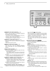
... GAIN AGC 10dB 20dB SQUELCH APC IF SHIFT TS TS SPCH LOCK APF @1 MEMORY SET SWITCH [M-SET] (p. 19) Used to 'copy and paste' the displayed frequency into a temporary memory. @2 MEMORY CLEAR SWITCH [M-CL] (p. 19) Push and hold to paste ( M disappears). • Frequency, mode, tuning step, memory name, etc. In this case, scan delay time is assigned, this control adjusts the scan delay time (scan pausing interval) during signal...
... GAIN AGC 10dB 20dB SQUELCH APC IF SHIFT TS TS SPCH LOCK APF @1 MEMORY SET SWITCH [M-SET] (p. 19) Used to 'copy and paste' the displayed frequency into a temporary memory. @2 MEMORY CLEAR SWITCH [M-CL] (p. 19) Push and hold to paste ( M disappears). • Frequency, mode, tuning step, memory name, etc. In this case, scan delay time is assigned, this control adjusts the scan delay time (scan pausing interval) during signal...
Instruction Manual
Page 7
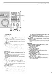
... start /stop priority scan. • Priority scan can be used for several functions as a skip channel. [AUTO] (p. 24) ¯ Push momentarily to the 4 Direct frequency input. • Keypad then [M-CH] - Specify memory bank then start programmed scan or auto write scan. [DLY D/S ] (p. 27) ¯ Push momentarily to select a scan resume condi- 1 PANEL DESCRIPTION ∞ OFF DLY kHz SEL-CH SKIP-CH IC-R8500...
... start /stop priority scan. • Priority scan can be used for several functions as a skip channel. [AUTO] (p. 24) ¯ Push momentarily to the 4 Direct frequency input. • Keypad then [M-CH] - Specify memory bank then start programmed scan or auto write scan. [DLY D/S ] (p. 27) ¯ Push momentarily to select a scan resume condi- 1 PANEL DESCRIPTION ∞ OFF DLY kHz SEL-CH SKIP-CH IC-R8500...
Instruction Manual
Page 8
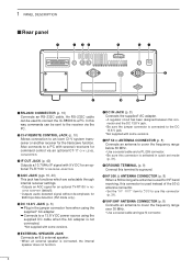
... speaker is connected to an Icom CI-V system transceiver or another receiver for an optional TV-R7100 TV RECEIVE ADAPTER. Also connects to cover the frequency range over 30 MHz. • Use a coaxial cable and type-N connector. 5 r AGC JACK (pgs. 16, 40) This jack has functions which are selectable through internal receiver settings. • Outputs an AGC signal for an optional TV-R7100 TV RECEIVE ADAPTER (default). • Outputs audio detected...
... speaker is connected to an Icom CI-V system transceiver or another receiver for an optional TV-R7100 TV RECEIVE ADAPTER. Also connects to cover the frequency range over 30 MHz. • Use a coaxial cable and type-N connector. 5 r AGC JACK (pgs. 16, 40) This jack has functions which are selectable through internal receiver settings. • Outputs an AGC signal for an optional TV-R7100 TV RECEIVE ADAPTER (default). • Outputs audio detected...

Instruction Manual
Page 13
... functions such as instant frequency/name programming using appropriate software. s Data demodulation terminal See p. 16 for recording control. (2 A/DC max.) [REC REMOTE] SCAN SET [REC OUT] 350 mVrms 4.7 kΩ Convenient: When an optional UT-102 VOICE SYNTHESIZER UNIT is changed. * When a set mode (p. 32). s Transceive function Icom CI-V transceivers or receivers can be used for details regarding connection and operation. IC-R8500 8 13 3.TXD (data output) 2.RXD (data input) 1 25...
... functions such as instant frequency/name programming using appropriate software. s Data demodulation terminal See p. 16 for recording control. (2 A/DC max.) [REC REMOTE] SCAN SET [REC OUT] 350 mVrms 4.7 kΩ Convenient: When an optional UT-102 VOICE SYNTHESIZER UNIT is changed. * When a set mode (p. 32). s Transceive function Icom CI-V transceivers or receivers can be used for details regarding connection and operation. IC-R8500 8 13 3.TXD (data output) 2.RXD (data input) 1 25...
Instruction Manual
Page 14
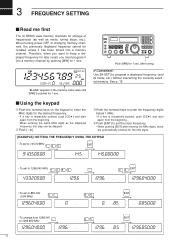
... the same MHz digits as mode, tuning steps, etc.). When turning power OFF or changing memory channels, the previously displayed frequency cannot be skipped. Push [ • t]. Ž Push the numeral keys to enter the frequency digits below 1 MHz. • If a key is mistakenly pushed, push [CE s] and start again from the beginning. Push [ENT] to set the input frequency. •...
... the same MHz digits as mode, tuning steps, etc.). When turning power OFF or changing memory channels, the previously displayed frequency cannot be skipped. Push [ • t]. Ž Push the numeral keys to enter the frequency digits below 1 MHz. • If a key is mistakenly pushed, push [CE s] and start again from the beginning. Push [ENT] to set the input frequency. •...
Instruction Manual
Page 15
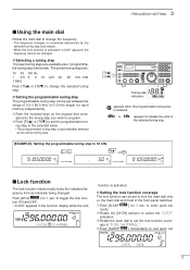
... : 10 50 100 Hz 1 2.5 5 9 10 12.5 20 1 MHz 25 100 kHz Push [TSY] or [TSZ] to change the frequency. • The frequency changes in the function display while the lock FM ∞ OFF DLY LOCK kHz *ICOM IC-R8500 function is activated ("LOCK" appears) the frequency cannot be set to toggle the lock function ON and OFF. • "LOCK" appears in increments determined by the selected...
... : 10 50 100 Hz 1 2.5 5 9 10 12.5 20 1 MHz 25 100 kHz Push [TSY] or [TSZ] to change the frequency. • The frequency changes in the function display while the lock FM ∞ OFF DLY LOCK kHz *ICOM IC-R8500 function is activated ("LOCK" appears) the frequency cannot be set to toggle the lock function ON and OFF. • "LOCK" appears in increments determined by the selected...
Instruction Manual
Page 16
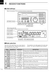
... kHz/-6 dB 13 Morse code communications. 4 RECEIVE FUNCTIONS s Initial settings Before turning power ON, set controls and switches as follows: Push [SLEEP] Push and hold [SPCH • LOCK] Push [NB/AFC] FM SLEEP LOCK NB AFC AGC-F APF-N RECV 10-ATT-20 BANK *ICOM ∞ OFF DLY kHz IC-R8500 Push [AGC] Push [10dB] and/or [20 dB] s Mode selection Push one of...
... kHz/-6 dB 13 Morse code communications. 4 RECEIVE FUNCTIONS s Initial settings Before turning power ON, set controls and switches as follows: Push [SLEEP] Push and hold [SPCH • LOCK] Push [NB/AFC] FM SLEEP LOCK NB AFC AGC-F APF-N RECV 10-ATT-20 BANK *ICOM ∞ OFF DLY kHz IC-R8500 Push [AGC] Push [10dB] and/or [20 dB] s Mode selection Push one of...
Instruction Manual
Page 17
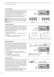
... of these indicators appears when the received signal is no interference. Noise squelch: Only acts on noise; Noise squelch threshold (not available in SSB, CW, WFM and AM narrow modes) When [SQUELCH] is not available in audio distortion. The IC-R8500's offcenter indicators appear in use. Set the shift control to receive. When one of the off -center frequency is automatically moved to the center...
... of these indicators appears when the received signal is no interference. Noise squelch: Only acts on noise; Noise squelch threshold (not available in SSB, CW, WFM and AM narrow modes) When [SQUELCH] is not available in audio distortion. The IC-R8500's offcenter indicators appear in use. Set the shift control to receive. When one of the off -center frequency is automatically moved to the center...
Instruction Manual
Page 18
... beat frequency oscillator. NOTE: When a strong signal is received while the noise blanker is useful in FM and WFM modes. no indicator appears when AGC slow is selected. [NB/AFC] SCAN SET switch NB OFF NB ON [APF] switch SCAN SET [APF] control APF is selected APF-N is activated. When eliminating interference with the IF shift function. AGC time constant cannot be turned OFF. The IC-R8500...
... beat frequency oscillator. NOTE: When a strong signal is received while the noise blanker is useful in FM and WFM modes. no indicator appears when AGC slow is selected. [NB/AFC] SCAN SET switch NB OFF NB ON [APF] switch SCAN SET [APF] control APF is selected APF-N is activated. When eliminating interference with the IF shift function. AGC time constant cannot be turned OFF. The IC-R8500...

Instruction Manual
Page 19
...; SCAN SET AF IN to [REC OUT] 2-conductor 3.5(d) plugs to [REC REMOTE] SQUELCH IN TU or TNC Personal computer D Receiving method ΠConnect a terminal unit as above. Select FM mode (or USB, CW modes for amateur RTTY): [Setting frequency(displayed freq.)]=[Desired freq.] + [Mark freq.] 16 Frequency settings depend on the mode used. FM mode: [Setting frequency(displayed freq.)]=[Desired freq.] USB mode: [Setting frequency(displayed freq.)]=[Desired freq.]-[Center of Mark and Space freq.] CW narrow mode: [Setting frequency(displayed freq.)]=[Desired freq.]-[Center of opening...
...; SCAN SET AF IN to [REC OUT] 2-conductor 3.5(d) plugs to [REC REMOTE] SQUELCH IN TU or TNC Personal computer D Receiving method ΠConnect a terminal unit as above. Select FM mode (or USB, CW modes for amateur RTTY): [Setting frequency(displayed freq.)]=[Desired freq.] + [Mark freq.] 16 Frequency settings depend on the mode used. FM mode: [Setting frequency(displayed freq.)]=[Desired freq.] USB mode: [Setting frequency(displayed freq.)]=[Desired freq.]-[Center of Mark and Space freq.] CW narrow mode: [Setting frequency(displayed freq.)]=[Desired freq.]-[Center of opening...
Instruction Manual
Page 20
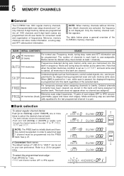
... the last programmed channel in this bank regardless of frequencies. NOTE: The FREE bank is not displayed. SKIP 100 memories Undesired signals such as CL&START and auto write scan is started, all 1000 channels and 5-digit bank names are programmed into 20 user banks for convenient recall and organisation of the selected bank. Convenient: Bank names The default names of...
... the last programmed channel in this bank regardless of frequencies. NOTE: The FREE bank is not displayed. SKIP 100 memories Undesired signals such as CL&START and auto write scan is started, all 1000 channels and 5-digit bank names are programmed into 20 user banks for convenient recall and organisation of the selected bank. Convenient: Bank names The default names of...
Instruction Manual
Page 27
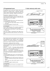
... frequencies are written into channels, starting from channel 0. AUTO CL&START : Previously written memories in the auto write bank. Preparation-written memories condition: Push and hold [PROG] to select the condition. Convenient: Direct range selection-The desired programmed scan range can be selected using the selected tuning step increments. SCANS 6 D Programmed scan Programmed scan (and auto memory write scan) searches for signals within a specified frequency range, using...
... frequencies are written into channels, starting from channel 0. AUTO CL&START : Previously written memories in the auto write bank. Preparation-written memories condition: Push and hold [PROG] to select the condition. Convenient: Direct range selection-The desired programmed scan range can be selected using the selected tuning step increments. SCANS 6 D Programmed scan Programmed scan (and auto memory write scan) searches for signals within a specified frequency range, using...

Instruction Manual
Page 28
... s Specifying skip channel and frequency • Specifying skip channels Œ Select the memory channel to stop the scan. Preparation-priority channel programming: Œ Push [PRIO] for 1 sec. or, push [PRIO] while operating another scan type during any time with one push. Set the desired frequency, mode and memory name. Ž Push [MW] for 1 sec. • "*SET*" appears in via the mode switches. • The mode select function...
... s Specifying skip channel and frequency • Specifying skip channels Œ Select the memory channel to stop the scan. Preparation-priority channel programming: Œ Push [PRIO] for 1 sec. or, push [PRIO] while operating another scan type during any time with one push. Set the desired frequency, mode and memory name. Ž Push [MW] for 1 sec. • "*SET*" appears in via the mode switches. • The mode select function...
Instruction Manual
Page 35
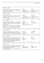
... SYNTHESIZER UNIT is selected, changing the frequency, operating mode, etc. When 2 or more IC-R8500's are connected to an optional CT-17 CI-V LEVEL CONVERTER, rotate the main dial to "ON" only when operating transceive with the IC-R8500 connected to an Icom CI-V radio. ENG JPN Voice synthesizer functions Voice synthesizer functions in Japanese. in English (default). AUTO Auto baud rate (default). When "ON" is installed, you...
... SYNTHESIZER UNIT is selected, changing the frequency, operating mode, etc. When 2 or more IC-R8500's are connected to an optional CT-17 CI-V LEVEL CONVERTER, rotate the main dial to "ON" only when operating transceive with the IC-R8500 connected to an Icom CI-V radio. ENG JPN Voice synthesizer functions Voice synthesizer functions in Japanese. in English (default). AUTO Auto baud rate (default). When "ON" is installed, you...

Instruction Manual
Page 38
... Reading operating freq. fd) FD Preamble code (fixed) IC-R8500's address (selectable in set mode) PC's address Command number (see table) Sub command number (see table) BCD code area ('REMARK' in table) End of message code Preamble code (fixed) PC's address IC-R8500's address (selectable in set mode) Command number Sub command number BCD code area End of message code 35 10 CONTROL COMMANDS The IC-R8500 can be connected to control the receiver s Command table Operation...
... Reading operating freq. fd) FD Preamble code (fixed) IC-R8500's address (selectable in set mode) PC's address Command number (see table) Sub command number (see table) BCD code area ('REMARK' in table) End of message code Preamble code (fixed) PC's address IC-R8500's address (selectable in set mode) Command number Sub command number BCD code area End of message code 35 10 CONTROL COMMANDS The IC-R8500 can be connected to control the receiver s Command table Operation...

Instruction Manual
Page 44
... to the receive frequency. • Wrong antenna connector is used for V/UHF and HF antenna. • Wrong antenna connector is selected in quick set . • The operating frequency is lower than • Set the frequency above 30 MHz when p. 13 30 MHz. (WFM mode cannot be set p. 31 mode. to turn ON when [POWER] is pushed in. • DC power cable is improperly connected. • A fuse is blown. • During AC adapter operation, the...
... to the receive frequency. • Wrong antenna connector is used for V/UHF and HF antenna. • Wrong antenna connector is selected in quick set . • The operating frequency is lower than • Set the frequency above 30 MHz when p. 13 30 MHz. (WFM mode cannot be set p. 31 mode. to turn ON when [POWER] is pushed in. • DC power cable is improperly connected. • A fuse is blown. • During AC adapter operation, the...

Instruction Manual
Page 45
...] to se- Memory channels in the selected bank. selected. scan edge channels or select a different does not function. the selected bank. programmed scan group. p. 19 p. 20 • [SQUELCH] is open and [∞] is indicated. MEMORY CHANNELS TROUBLESHOOTING 13 PROBLEM POSSIBLE CAUSE SOLUTION REF. Memory name cannot be "BANK" is selected. • Turn [SQUELCH] CW until the center frequency is erased after setting the name.
...] to se- Memory channels in the selected bank. selected. scan edge channels or select a different does not function. the selected bank. programmed scan group. p. 19 p. 20 • [SQUELCH] is open and [∞] is indicated. MEMORY CHANNELS TROUBLESHOOTING 13 PROBLEM POSSIBLE CAUSE SOLUTION REF. Memory name cannot be "BANK" is selected. • Turn [SQUELCH] CW until the center frequency is erased after setting the name.


