Instruction Manual
Page 3
... be hot. Immediately turn over the transceiver. R CAUTION! In particular, incorrect settings for advice. R CAUTION! NEVER block any problems caused by Icom Inc., could void your authority to rain, snow or any unstable place (such as benzine or al- Heat dissipation may be ...the transceiver to operate this device, not expressly approved by unauthorized internal adjustment. R CAUTION! Always have two people available to the IC-7700 may result in any liquids. The line-voltage receptacle must be near the transceiver and must be damaged. AVOID using or storing ...
... be hot. Immediately turn over the transceiver. R CAUTION! In particular, incorrect settings for advice. R CAUTION! NEVER block any problems caused by Icom Inc., could void your authority to rain, snow or any unstable place (such as benzine or al- Heat dissipation may be ...the transceiver to operate this device, not expressly approved by unauthorized internal adjustment. R CAUTION! Always have two people available to the IC-7700 may result in any liquids. The line-voltage receptacle must be near the transceiver and must be damaged. AVOID using or storing ...
Instruction Manual
Page 22
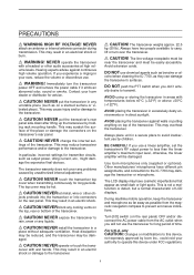
... DISPLAY TERMINAL [EXT-DISPLAY] (p. 2-7) Connects to prevent electrical shocks, TVI, BCI and other problems. y CIRCUIT BREAKER Cuts off the AC input when over-current occurs. Can be used to an... 2 [ANT 2] (p. 2-5) e ANTENNA CONNECTOR 3 [ANT 3] (p. 2-5) r ANTENNA CONNECTOR 4 [ANT 4] (p. 2-5) Accept a 50 Ω antenna with another Icom CI-V transceiver or receiver. !0 RS-232C TERMINAL [RS-232C] (p. 2-6) Connects an RS-232C cable, D-sub 9-pin to connect the IC-7700 to a PC through a LAN (Local Area Network). 1 PANEL DESCRIPTION ■ Rear panel q w e r t y u i o !0 ANT 1 ANT 2...
... DISPLAY TERMINAL [EXT-DISPLAY] (p. 2-7) Connects to prevent electrical shocks, TVI, BCI and other problems. y CIRCUIT BREAKER Cuts off the AC input when over-current occurs. Can be used to an... 2 [ANT 2] (p. 2-5) e ANTENNA CONNECTOR 3 [ANT 3] (p. 2-5) r ANTENNA CONNECTOR 4 [ANT 4] (p. 2-5) Accept a 50 Ω antenna with another Icom CI-V transceiver or receiver. !0 RS-232C TERMINAL [RS-232C] (p. 2-6) Connects an RS-232C cable, D-sub 9-pin to connect the IC-7700 to a PC through a LAN (Local Area Network). 1 PANEL DESCRIPTION ■ Rear panel q w e r t y u i o !0 ANT 1 ANT 2...
Instruction Manual
Page 30
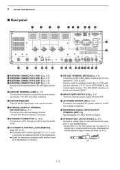
... a specified frequency range and SWR may be a coaxial cable. The IC-7700 has an SWR meter to monitor the antenna SWR continuously. ■ USB-Memory connection (USB-Memory: Not supplied by Icom) Connect the USB-Memory* to a gas or electric pipe, since...antenna, and feedline. 2 INSTALLATION AND CONNECTIONS ■ Grounding To prevent electrical shock, television interference (TVI), broadcast interference (BCI) and other problems, ground the transceiver through the GROUND terminal on your transceiver from lightning by using a single antenna, use the [ANT1] connector. r Screw...
... a specified frequency range and SWR may be a coaxial cable. The IC-7700 has an SWR meter to monitor the antenna SWR continuously. ■ USB-Memory connection (USB-Memory: Not supplied by Icom) Connect the USB-Memory* to a gas or electric pipe, since...antenna, and feedline. 2 INSTALLATION AND CONNECTIONS ■ Grounding To prevent electrical shock, television interference (TVI), broadcast interference (BCI) and other problems, ground the transceiver through the GROUND terminal on your transceiver from lightning by using a single antenna, use the [ANT1] connector. r Screw...
Instruction Manual
Page 31
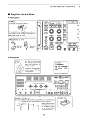
... bands, ANT 2 for 21-28 MHz bands ANT3 for 50 MHz band, ANT 4 for receive antenna. Straight key 2-5 Grounding prevents electrical shocks, TVI and other problems. AC outlet R WARNING: Use the supplied AC power cable only. SP ACC 2 1 RELAY ALC ALC ADJ S/P DIF OUT IN CW KEY REF I RX ANT OUT...
... bands, ANT 2 for 21-28 MHz bands ANT3 for 50 MHz band, ANT 4 for receive antenna. Straight key 2-5 Grounding prevents electrical shocks, TVI and other problems. AC outlet R WARNING: Use the supplied AC power cable only. SP ACC 2 1 RELAY ALC ALC ADJ S/P DIF OUT IN CW KEY REF I RX ANT OUT...
Instruction Manual
Page 182
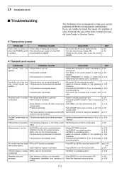
...OFF. when the [POWER] switch • The internal power supply is too far clockwise. p. 3-2 • Check for 1 sec. D Transmit and receive PROBLEM No sounds from speaker. SOLUTION REF. • Rotate [AF] clockwise to a suitable position. to manually p. 10-6 tune the antenna. • Push ... and • The antenna is improperly connected. 13 MAINTENANCE ■ Troubleshooting The following chart is designed to help you nearest Icom Dealer or Service Center. SOLUTION REF. • Re-connect the AC power cable correctly. Received audio is unclear • ...
...OFF. when the [POWER] switch • The internal power supply is too far clockwise. p. 3-2 • Check for 1 sec. D Transmit and receive PROBLEM No sounds from speaker. SOLUTION REF. • Rotate [AF] clockwise to a suitable position. to manually p. 10-6 tune the antenna. • Push ... and • The antenna is improperly connected. 13 MAINTENANCE ■ Troubleshooting The following chart is designed to help you nearest Icom Dealer or Service Center. SOLUTION REF. • Re-connect the AC power cable correctly. Received audio is unclear • ...
Instruction Manual
Page 183
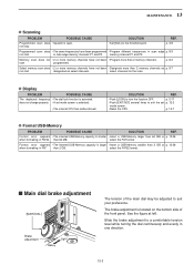
...13-3 Memory scan does not • 2 or more memory channels have not been • Designate more than 2 memory channels. D Display PROBLEM POSSIBLE CAUSE The displayed frequency • The dial lock function is smaller • Insert a USB-Memory larger than 64 MB or p. 12-...the FAT32 format. ■ Main dial brake adjustment [MAIN DIAL] Brake adjustment Heavy Light The tension of the front panel. MAINTENANCE 13 D Scanning PROBLEM POSSIBLE CAUSE SOLUTION REF. not stop. • Set [SQL] to exit the set mode screen is larger • Insert a USB-Memory smaller ...
...13-3 Memory scan does not • 2 or more memory channels have not been • Designate more than 2 memory channels. D Display PROBLEM POSSIBLE CAUSE The displayed frequency • The dial lock function is smaller • Insert a USB-Memory larger than 64 MB or p. 12-...the FAT32 format. ■ Main dial brake adjustment [MAIN DIAL] Brake adjustment Heavy Light The tension of the front panel. MAINTENANCE 13 D Scanning PROBLEM POSSIBLE CAUSE SOLUTION REF. not stop. • Set [SQL] to exit the set mode screen is larger • Insert a USB-Memory smaller ...


