
Instruction Manual
Page 6
... 5 MHz band operation (USA version only 4-3 ■ Operating CW 4-4 D Convenient functions for receive 4-4 D Convenient functions for transmit 4-5 D About CW reverse mode 4-5 D About CW pitch control 4-5 D CW side tone function 4-5 D APF (Audio Peak Filter) operation 4-6 ■ Electronic keyer functions 4-7 D Memory keyer screen 4-8 D Editing a memory keyer 4-9 D Contest number set mode 4-10 D Keyer set mode 4-11 ■ Operating RTTY (FSK 4-13...
... 5 MHz band operation (USA version only 4-3 ■ Operating CW 4-4 D Convenient functions for receive 4-4 D Convenient functions for transmit 4-5 D About CW reverse mode 4-5 D About CW pitch control 4-5 D CW side tone function 4-5 D APF (Audio Peak Filter) operation 4-6 ■ Electronic keyer functions 4-7 D Memory keyer screen 4-8 D Editing a memory keyer 4-9 D Contest number set mode 4-10 D Keyer set mode 4-11 ■ Operating RTTY (FSK 4-13...
Instruction Manual
Page 12
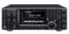
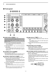
...are connected, the internal speaker or connected external speaker does not function. y ELECTRONIC KEYER JACK [ELEC-KEY] (p. 2-5) Accepts a paddle to activate the internal electronic keyer for CW operation. • You can be reversed in keyer set mode when pushed and held for 1 sec. e ANTENNA TUNER SWITCH TUNER ...when tuner is available for 1 sec. See [CW KEY] on p. 1-12. • Keyer polarity (dot and dash) can select internal electronic keyer, bug-key or straight key operation in keyer set mode. (p. 4-12) • A 4-channel memory keyer is turned OFF (bypassed). ➥ Tunes the ...
...are connected, the internal speaker or connected external speaker does not function. y ELECTRONIC KEYER JACK [ELEC-KEY] (p. 2-5) Accepts a paddle to activate the internal electronic keyer for CW operation. • You can be reversed in keyer set mode when pushed and held for 1 sec. e ANTENNA TUNER SWITCH TUNER ...when tuner is available for 1 sec. See [CW KEY] on p. 1-12. • Keyer polarity (dot and dash) can select internal electronic keyer, bug-key or straight key operation in keyer set mode. (p. 4-12) • A 4-channel memory keyer is turned OFF (bypassed). ➥ Tunes the ...
Instruction Manual
Page 13
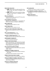
...range. Deep Squelch threshold Noise squelch Shallow Squelch is the VOX function? Long delay for slow speed keying Short delay for an Icom microphone Increases Decreases Decreases Increases o VOX SWITCH VOX ➥ Push to set the microphone gain. Recommended level for high speed keying... MONITOR switch setting in SSB, AM and FM modes can monitor the receive signal between CW dots and dashes. !2 ELECTRONIC CW KEYER SPEED CONTROL [KEY SPEED] (p. 4-4) Adjusts keying speed for the internal electronic CW keyer. • 6 wpm (min.) to -receive switching delay time for 1 sec. ...
...range. Deep Squelch threshold Noise squelch Shallow Squelch is the VOX function? Long delay for slow speed keying Short delay for an Icom microphone Increases Decreases Decreases Increases o VOX SWITCH VOX ➥ Push to set the microphone gain. Recommended level for high speed keying... MONITOR switch setting in SSB, AM and FM modes can monitor the receive signal between CW dots and dashes. !2 ELECTRONIC CW KEYER SPEED CONTROL [KEY SPEED] (p. 4-4) Adjusts keying speed for the internal electronic CW keyer. • 6 wpm (min.) to -receive switching delay time for 1 sec. ...
Instruction Manual
Page 22
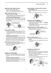
... with another Icom CI-V transceiver or receiver. !0 RS-232C TERMINAL [RS-232C] (p. 2-6) Connects an RS-232C cable, D-sub 9-pin to connect the IC-7700 to an AC line-voltage receptacle. !3 REFERENCE SIGNAL INPUT/OUTPUT TERMINAL [REF I/O] Inputs/outputs a 10 MHz reference signal. !4 STRAIGHT KEY JACK [CW KEY] (p. 2-5) Accepts a straight key or external electronic keyer with...
... with another Icom CI-V transceiver or receiver. !0 RS-232C TERMINAL [RS-232C] (p. 2-6) Connects an RS-232C cable, D-sub 9-pin to connect the IC-7700 to an AC line-voltage receptacle. !3 REFERENCE SIGNAL INPUT/OUTPUT TERMINAL [REF I/O] Inputs/outputs a 10 MHz reference signal. !4 STRAIGHT KEY JACK [CW KEY] (p. 2-5) Accepts a straight key or external electronic keyer with...
Instruction Manual
Page 25
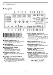
... function is in RTTY mode. (p. 4-14) o CLOCK READOUT Shows the current time. This function is available in use. This function is available in CW mode. (p. 4-6) ➥ " TPF " appears when the twin peak filter function is in use. !6 FREQUENCY READOUTS Shows the operating frequency. !7 ...MULTI-FUNCTION SCREEN Shows the screens for the multi-function digital meter, spectrum scope, voice recorder, memory list, scan, memory keyer, RTTY decoder, PSK decoder, IF filter selection or set modes, etc. !8 LCD FUNCTION SWITCH GUIDE Indicates the function of the multi-function ...
... function is in RTTY mode. (p. 4-14) o CLOCK READOUT Shows the current time. This function is available in use. This function is available in CW mode. (p. 4-6) ➥ " TPF " appears when the twin peak filter function is in use. !6 FREQUENCY READOUTS Shows the operating frequency. !7 ...MULTI-FUNCTION SCREEN Shows the screens for the multi-function digital meter, spectrum scope, voice recorder, memory list, scan, memory keyer, RTTY decoder, PSK decoder, IF filter selection or set modes, etc. !8 LCD FUNCTION SWITCH GUIDE Indicates the function of the multi-function ...
Instruction Manual
Page 26
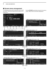
...) F-5 • Set mode menu screen (p. 12-2) F-3 F-7 1-16 Choose the desired screen using the following screens can be selected from the start up screen. p. 9-4) • Memory keyer screen (CW mode; p. 4-8) F-2 F-5 • Scan screen (Memory mode; p. 4-21) F-1 F-2 F-3 F-4 F-5 F-6 F-7 F-3 • Spectrum scope screen (p. 5-2) • Memory list screen (p. 8-5) • Voice recorder screen (p. 7-3) F-4 • Scan screen (VFO mode...
...) F-5 • Set mode menu screen (p. 12-2) F-3 F-7 1-16 Choose the desired screen using the following screens can be selected from the start up screen. p. 9-4) • Memory keyer screen (CW mode; p. 4-8) F-2 F-5 • Scan screen (Memory mode; p. 4-21) F-1 F-2 F-3 F-4 F-5 F-6 F-7 F-3 • Spectrum scope screen (p. 5-2) • Memory list screen (p. 8-5) • Voice recorder screen (p. 7-3) F-4 • Scan screen (VFO mode...
Instruction Manual
Page 31
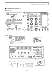
...ACC 2 1 RELAY ALC ALC ADJ S/P DIF OUT IN CW KEY REF I RX ANT OUT IN X-VERTER DC OUT 15V MAX1A EXT METER KEYPAD E X T- NOTE: Attach the supplied antenna connector cap when no antenna or external equipment is changed in keyer set mode. (p. 4-12) Microphones (p. 2-10) Optional... gauge wire or strap available and make the connection as short as possible. 2 INSTALLATION AND CONNECTIONS ■ Required connections D Front panel CW key Connects an electronic keyer. DISPL AY 15A GND REMOTE RS-232C AC I /O 10MHz -10dBm Antenna 1, 2, 3, 4 (p. 2-4) [Example]: ANT1 for 1.8-18...
...ACC 2 1 RELAY ALC ALC ADJ S/P DIF OUT IN CW KEY REF I RX ANT OUT IN X-VERTER DC OUT 15V MAX1A EXT METER KEYPAD E X T- NOTE: Attach the supplied antenna connector cap when no antenna or external equipment is changed in keyer set mode. (p. 4-12) Microphones (p. 2-10) Optional... gauge wire or strap available and make the connection as short as possible. 2 INSTALLATION AND CONNECTIONS ■ Required connections D Front panel CW key Connects an electronic keyer. DISPL AY 15A GND REMOTE RS-232C AC I /O 10MHz -10dBm Antenna 1, 2, 3, 4 (p. 2-4) [Example]: ANT1 for 1.8-18...
Instruction Manual
Page 33
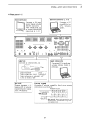
... (approx.) DC for external equipment power supply. (max. 1 A capacity) External keypad Connects an external keypad for direct voice memory and memory keyer controls. Video output signal can be turned ON and OFF in ACC set mode (p. 12-11) 2 INSTALLATION AND CONNECTIONS Ethernet connector (p. 16...Connects a PC for the CPU firmware update. ANT 1 ANT 2 ANT 3 ANT 4 E X T- SP ACC 2 1 RELAY ALC ALC ADJ S/P DIF OUT IN CW KEY REF I RX ANT OUT IN X-VERTER DC OUT 15V MAX1A EXT METER KEYPAD E X T- D Rear panel- 2 External Display Connects a PC-style monitor display...
... (approx.) DC for external equipment power supply. (max. 1 A capacity) External keypad Connects an external keypad for direct voice memory and memory keyer controls. Video output signal can be turned ON and OFF in ACC set mode (p. 12-11) 2 INSTALLATION AND CONNECTIONS Ethernet connector (p. 16...Connects a PC for the CPU firmware update. ANT 1 ANT 2 ANT 3 ANT 4 E X T- SP ACC 2 1 RELAY ALC ALC ADJ S/P DIF OUT IN CW KEY REF I RX ANT OUT IN X-VERTER DC OUT 15V MAX1A EXT METER KEYPAD E X T- D Rear panel- 2 External Display Connects a PC-style monitor display...

Instruction Manual
Page 53
... 5 MHz band operation (USA version only 4-3 ■ Operating CW 4-4 D Convenient functions for receive 4-4 D Convenient functions for transmit 4-5 D About CW reverse mode 4-5 D About CW pitch control 4-5 D CW side tone function 4-5 D APF (Audio Peak Filter) operation 4-6 ■ Electronic keyer functions 4-7 D Memory keyer screen 4-8 D Editing a memory keyer 4-9 D Contest number set mode 4-10 D Keyer set mode 4-11 ■ Operating RTTY (FSK 4-13...
... 5 MHz band operation (USA version only 4-3 ■ Operating CW 4-4 D Convenient functions for receive 4-4 D Convenient functions for transmit 4-5 D About CW reverse mode 4-5 D About CW pitch control 4-5 D CW side tone function 4-5 D APF (Audio Peak Filter) operation 4-6 ■ Electronic keyer functions 4-7 D Memory keyer screen 4-8 D Editing a memory keyer 4-9 D Contest number set mode 4-10 D Keyer set mode 4-11 ■ Operating RTTY (FSK 4-13...
Instruction Manual
Page 56
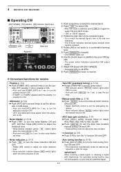
...Adjust CW speed with interference, the automatic tuning function may not tune properly, or tune onto an undesired signal. 4-4 to turn the attenuator function OFF. • "ATT" and attenuation level appear when the attenu- nal within 6-48 WPM. y Use the electric keyer or ...) several times to transmit. • [TX] indicator lights red. to key your CW signals. • The power meter indicates transmitted CW output power. w Push CW to select CW. • After CW mode is selected, push CW to adjust the threshold level. • Noise blanker indicator (above NR switch) lights ...
...Adjust CW speed with interference, the automatic tuning function may not tune properly, or tune onto an undesired signal. 4-4 to turn the attenuator function OFF. • "ATT" and attenuation level appear when the attenu- nal within 6-48 WPM. y Use the electric keyer or ...) several times to transmit. • [TX] indicator lights red. to key your CW signals. • The power meter indicates transmitted CW output power. w Push CW to select CW. • After CW mode is selected, push CW to adjust the threshold level. • Noise blanker indicator (above NR switch) lights ...
Instruction Manual
Page 59
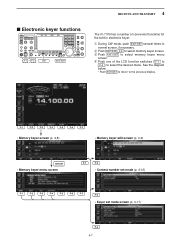
... of convenient functions for the built-in electronic keyer. F-1 F-2 F-3 F-4 F-5 F-6 F-7 • Memory keyer screen (p. 4-8) • Memory keyer edit screen (p. 4-9) EXIT/SET • Memory keyer menu screen F-1 F-2 • Contest number set mode (p. 4-10) F-1 F-2 F-3 F-4 F-5 F-6 F-7 F-3 • Keyer set mode screen (p. 4-11) F-4 4-7 w Push [KEYER] F-3 to select memory keyer screen. F-4 CW EXIT/SET 4 RECEIVE AND TRANSMIT The IC-7700 has a number of the LCD function switches...
... of convenient functions for the built-in electronic keyer. F-1 F-2 F-3 F-4 F-5 F-6 F-7 • Memory keyer screen (p. 4-8) • Memory keyer edit screen (p. 4-9) EXIT/SET • Memory keyer menu screen F-1 F-2 • Contest number set mode (p. 4-10) F-1 F-2 F-3 F-4 F-5 F-6 F-7 F-3 • Keyer set mode screen (p. 4-11) F-4 4-7 w Push [KEYER] F-3 to select memory keyer screen. F-4 CW EXIT/SET 4 RECEIVE AND TRANSMIT The IC-7700 has a number of the LCD function switches...

Instruction Manual
Page 60
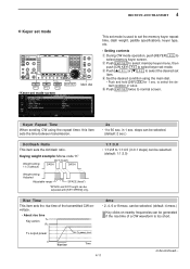
w Push TRANSMIT to set characters can be sent using the edit menu. • Transmitting q During CW mode operation, push [KEYER] F-3 to a station a second time. 4 RECEIVE AND TRANSMIT D Memory keyer screen M1 - M4 -1 F-1 F-4 F-5 TRANSMIT CW • Memory keyer screen EXIT/SET Pre-set the transceiver to normal screen. 4-8 repeatedly sends the contents; For your information When an...
w Push TRANSMIT to set characters can be sent using the edit menu. • Transmitting q During CW mode operation, push [KEYER] F-3 to a station a second time. 4 RECEIVE AND TRANSMIT D Memory keyer screen M1 - M4 -1 F-1 F-4 F-5 TRANSMIT CW • Memory keyer screen EXIT/SET Pre-set the transceiver to normal screen. 4-8 repeatedly sends the contents; For your information When an...

Instruction Manual
Page 61
... 3 • Pre-programmed contents CH Contents M1 CQ TEST CQ TEST DE ICOM ICOM TEST M2 UR 5NN✱ BK M3 CFM TU M4 QRZ? Total capacity of the memory keyer memories can be set using the main dial); Put "^" before a text string such as ^AR, and ... to transmit a string of Channel 1 (M1) is 70 characters per memory channel. • Programming contents q During CW mode operation, push [KEYER] F-3 to select the character, or push the keypad for one memory keyer channel at a time. Key selection Editable characters ABC A to Z (capital letters) 123 0 to 9 (numbers) Symbol / ...
... 3 • Pre-programmed contents CH Contents M1 CQ TEST CQ TEST DE ICOM ICOM TEST M2 UR 5NN✱ BK M3 CFM TU M4 QRZ? Total capacity of the memory keyer memories can be set using the main dial); Put "^" before a text string such as ^AR, and ... to transmit a string of Channel 1 (M1) is 70 characters per memory channel. • Programming contents q During CW mode operation, push [KEYER] F-3 to select the character, or push the keypad for one memory keyer channel at a time. Key selection Editable characters ABC A to Z (capital letters) 123 0 to 9 (numbers) Symbol / ...

Instruction Manual
Page 62
...will contain the contest serial number exchange. to reset the current number to select the default condition or value. w Push EXIT/SET to select memory keyer menu, then push [001] F-3 to select contest serial number set item. r Set the desired condition using the main dial. • Push ...and hold [001CLR] F-4 for the count-up trigger, etc. • Setting contents q During CW mode operation, push [KEYER] F-3 to as T. Short morse numbers are also referred to select memory keyer screen. M2 • M1, M2, M3 and M4 can be set. (default: M2) Present Number This ...
...will contain the contest serial number exchange. to reset the current number to select the default condition or value. w Push EXIT/SET to select memory keyer menu, then push [001] F-3 to select contest serial number set item. r Set the desired condition using the main dial. • Push ...and hold [001CLR] F-4 for the count-up trigger, etc. • Setting contents q During CW mode operation, push [KEYER] F-3 to as T. Short morse numbers are also referred to select memory keyer screen. M2 • M1, M2, M3 and M4 can be set. (default: M2) Present Number This ...
Instruction Manual
Page 63
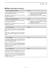
.... (default: 1:1:3.0) Rise Time This item sets the rise time of a CW waveform is used to set the memory keyer repeat time, dash weight, paddle specifications, keyer type, etc. • Setting contents q During CW mode operation, push [KEYER] F-3 to select the desired set item. can be selected. (default: ... w Push EXIT/SET to select memory keyer menu, then push [CW KEY] F-4 to be selected. (default: 2 sec.) Dot/Dash Ratio This item sets the dot/dash ratio. 4 RECEIVE AND TRANSMIT D Keyer set mode ∫ √ DEF F-1 F-2 F-4 • Keyer set mode screen EXIT/SET Main dial ...
.... (default: 1:1:3.0) Rise Time This item sets the rise time of a CW waveform is used to set the memory keyer repeat time, dash weight, paddle specifications, keyer type, etc. • Setting contents q During CW mode operation, push [KEYER] F-3 to select the desired set item. can be selected. (default: ... w Push EXIT/SET to select memory keyer menu, then push [CW KEY] F-4 to be selected. (default: 2 sec.) Dot/Dash Ratio This item sets the dot/dash ratio. 4 RECEIVE AND TRANSMIT D Keyer set mode ∫ √ DEF F-1 F-2 F-4 • Keyer set mode screen EXIT/SET Main dial ...

Instruction Manual
Page 64
... • ON • OFF : [UP]/[DN] switches can be used for CW. : [UP]/[DN] switches cannot be used as a paddle. Normal • Normal and reverse polarity can be selected. (default: ELEC-KEY) Mic Up/Down Keyer This item allows you to be used for [ELEC-KEY] connector on the front panel. NOTE... cannot be selected. ELE-KEY • ELEC-KEY, BUG-KEY and Straight key can be changed using the [UP]/[DN] switches. 4-12 4 RECEIVE AND TRANSMIT D Keyer set the microphone [UP]/[DN] keys to set mode (continued) Paddle Polarity This item sets the paddle dot-dash polarity.
... • ON • OFF : [UP]/[DN] switches can be used for CW. : [UP]/[DN] switches cannot be used as a paddle. Normal • Normal and reverse polarity can be selected. (default: ELEC-KEY) Mic Up/Down Keyer This item allows you to be used for [ELEC-KEY] connector on the front panel. NOTE... cannot be selected. ELE-KEY • ELEC-KEY, BUG-KEY and Straight key can be changed using the [UP]/[DN] switches. 4-12 4 RECEIVE AND TRANSMIT D Keyer set the microphone [UP]/[DN] keys to set mode (continued) Paddle Polarity This item sets the paddle dot-dash polarity.
Instruction Manual
Page 171
...: External keypad does not function. (default) External Keypad (KEYER) Sets the external keypad for each CI-V transceiver has its own Icom standard address in hexadecimal code. When "ON" is 74h. on the IC-7700 automatically changes those of external keypad switches, transmits the desired voice... message contents during CW mode operation. • OFF : External keypad ...
...: External keypad does not function. (default) External Keypad (KEYER) Sets the external keypad for each CI-V transceiver has its own Icom standard address in hexadecimal code. When "ON" is 74h. on the IC-7700 automatically changes those of external keypad switches, transmits the desired voice... message contents during CW mode operation. • OFF : External keypad ...

Instruction Manual
Page 192
... sec. 14 CONTROL COMMAND D Command table (continued) Command 14 Sub command Description 18 + Level data 19 + Level data [CONTRAST] setting (0=max. CW) 15 01 Read squelch condition 02 Read S-meter level 11 Read RF power meter 12 Read SWR meter 13 Read ALC meter 14 Read COMP...1; 2=preamp 2) 12 Send/read AGC selection (0=OFF; 1=Slow; 2=Mid; 3=Fast) 22 Send/read noise blanker setting (0=OFF; 1=ON) 32 Send/read memory keyer con- CW) [BRIGHT] setting (0=max. CCW to 255=max. ting (0=OFF; 1=ON) 53 Send/read RX antenna connector setting (0=OFF; 1=ON) 19 00 Read the ...
... sec. 14 CONTROL COMMAND D Command table (continued) Command 14 Sub command Description 18 + Level data 19 + Level data [CONTRAST] setting (0=max. CW) 15 01 Read squelch condition 02 Read S-meter level 11 Read RF power meter 12 Read SWR meter 13 Read ALC meter 14 Read COMP...1; 2=preamp 2) 12 Send/read AGC selection (0=OFF; 1=Slow; 2=Mid; 3=Fast) 22 Send/read noise blanker setting (0=OFF; 1=ON) 32 Send/read memory keyer con- CW) [BRIGHT] setting (0=max. CCW to 255=max. ting (0=OFF; 1=ON) 53 Send/read RX antenna connector setting (0=OFF; 1=ON) 19 00 Read the ...

Instruction Manual
Page 194
tion (0=DIGI-SEL, 1=APF) 050090 Send/read SSB/CW synchronous tuning function (0=OFF, 1=ON) 050091 Send/read CW normal side set (0=LSB, 1=USB) 050192 Set/read APF type (0=SHARP, 1=SOFT) 050093 Send/read external keypad set for voice memory (0=OFF, 1=ON) 050094 ... details) Send/read scope edge frequencies for 20.00 to 22.00 MHz band (see p. 14-10 for details) Send/read scope edge frequencies for keyer memory (0=OFF, 1=ON) 050095 Send/read keyboard repeat delay (10=100 msec. 14 CONTROL COMMAND D Command table (continued) Command Sub command Description 1A 050077 ...
tion (0=DIGI-SEL, 1=APF) 050090 Send/read SSB/CW synchronous tuning function (0=OFF, 1=ON) 050091 Send/read CW normal side set (0=LSB, 1=USB) 050192 Set/read APF type (0=SHARP, 1=SOFT) 050093 Send/read external keypad set for voice memory (0=OFF, 1=ON) 050094 ... details) Send/read scope edge frequencies for 20.00 to 22.00 MHz band (see p. 14-10 for details) Send/read scope edge frequencies for keyer memory (0=OFF, 1=ON) 050095 Send/read keyboard repeat delay (10=100 msec. 14 CONTROL COMMAND D Command table (continued) Command Sub command Description 1A 050077 ...

Instruction Manual
Page 195
... for details) Send/read PSK AFC function tuning range (0=±8 Hz, 1=±15 Hz) Send/read PSK time stamp set (0=OFF, 1=ON) 050128 Send/read CW keyer repeat time (1=1 sec. cies for 30.00 to 45=1:1:4.5) 050135 Send/read rise time (0=2 msec., 1=4 msec., 2=6 msec., 3=8 msec.) 050136 Send/read paddle polarity (0=... (0=Straight, 1=Bug-key, 2=ELEC-Key) 050138 Send/read scope edge frequen- to 60=60 sec.) 050134 Send/read CW keyer dot/dash ratio (28=1:1:2.8 to 45.00 MHz band (see p. 14-10 for details) 050126 Send/read mic. CONTROL COMMAND 14 D Command table (...
... for details) Send/read PSK AFC function tuning range (0=±8 Hz, 1=±15 Hz) Send/read PSK time stamp set (0=OFF, 1=ON) 050128 Send/read CW keyer repeat time (1=1 sec. cies for 30.00 to 45=1:1:4.5) 050135 Send/read rise time (0=2 msec., 1=4 msec., 2=6 msec., 3=8 msec.) 050136 Send/read paddle polarity (0=... (0=Straight, 1=Bug-key, 2=ELEC-Key) 050138 Send/read scope edge frequen- to 60=60 sec.) 050134 Send/read CW keyer dot/dash ratio (28=1:1:2.8 to 45.00 MHz band (see p. 14-10 for details) 050126 Send/read mic. CONTROL COMMAND 14 D Command table (...
