
Instruction Manual
Page 1
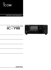
INSTRUCTION MANUAL HF ALL BAND TRANSCEIVER i718 This device complies with Part 15 of the FCC rules. Operation is subject to the following two conditions: (1) This device may not cause harmful interference, and (2) this device must accept any interference received, including interference that may cause undesired operation.
INSTRUCTION MANUAL HF ALL BAND TRANSCEIVER i718 This device complies with Part 15 of the FCC rules. Operation is subject to the following two conditions: (1) This device may not cause harmful interference, and (2) this device must accept any interference received, including interference that may cause undesired operation.
Instruction Manual
Page 2
...Radio Equipment). The heatsink will avoid possible damage to the transceiver by ignition voltage spikes. BE CAREFUL! Use Icom microphones only (supplied or optional). This manual contains important safety and operating instructions for extended periods. R NEVER let metal, wire or other objects touch ... i NEVER attach an antenna or internal antenna connector during transmission. R NEVER apply AC to the transceiver if left there for the IC-718. AVOID placing the transceiver against walls or putting anything on the serial number seal comply with temperatures below -10°C (+14°...
...Radio Equipment). The heatsink will avoid possible damage to the transceiver by ignition voltage spikes. BE CAREFUL! Use Icom microphones only (supplied or optional). This manual contains important safety and operating instructions for extended periods. R NEVER let metal, wire or other objects touch ... i NEVER attach an antenna or internal antenna connector during transmission. R NEVER apply AC to the transceiver if left there for the IC-718. AVOID placing the transceiver against walls or putting anything on the serial number seal comply with temperatures below -10°C (+14°...
Instruction Manual
Page 5
... and OFF. tween LSB or USB. • Push [MODE] for the selected operating mode. @1 MODE SWITCHES [LSB/USB]/[CW/CW- " " appears on the display. 3 to manually tune the tuner. • An optional antenna tuner must be connected. ➥ Push for 1 sec. The noise blanker reduces pulse-type noise such as discribed...
... and OFF. tween LSB or USB. • Push [MODE] for the selected operating mode. @1 MODE SWITCHES [LSB/USB]/[CW/CW- " " appears on the display. 3 to manually tune the tuner. • An optional antenna tuner must be connected. ➥ Push for 1 sec. The noise blanker reduces pulse-type noise such as discribed...
Instruction Manual
Page 11
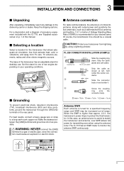
...antenna SWR continuously. 9 PL-259 CONNECTOR INSTALLATION EXAMPLE q Coupling ring w e 30 mm 10 mm (soft solder) Slide the coupling ring down. The IC-718 has an SWR meter to a long earth-sunk copper rod. Low SWR allows full power for transmitting even when using a lightning arrestor. Set the ... could cause an explosion or electric shock. R WARNING: NEVER connect the [GND] terminal to the delivering carrier or dealer. In this manual. Slide the connector body on the rear panel. Make the distance between the [GND] terminal and ground as short as possible.
...antenna SWR continuously. 9 PL-259 CONNECTOR INSTALLATION EXAMPLE q Coupling ring w e 30 mm 10 mm (soft solder) Slide the coupling ring down. The IC-718 has an SWR meter to a long earth-sunk copper rod. Low SWR allows full power for transmitting even when using a lightning arrestor. Set the ... could cause an explosion or electric shock. R WARNING: NEVER connect the [GND] terminal to the delivering carrier or dealer. In this manual. Slide the connector body on the rear panel. Make the distance between the [GND] terminal and ground as short as possible.
Instruction Manual
Page 16
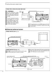
... ALC input level must be in the range 0 V to the linear amplifier instruction manual. s External antenna tuners CONNECTING THE AH-4 (p. 29) Long wire or optional AH-2b Coaxial cable (from the AH-4) Control cable IC-718 Ground Ground AH-4 CONNECTING THE AT-180 (p. 28) DO NOT! connect AT-180 and AH...-4 at the same time. To an antenna RF OUTPUT RF INPUT SEND ALC Non-Icom linear amplifier 50 Ω coaxial cable ANT IC-718 SEND 13 9 10 11 12 5678 1234 ALC The specifications for the SEND relay are 16 V DC 2 A. Turn the...
... ALC input level must be in the range 0 V to the linear amplifier instruction manual. s External antenna tuners CONNECTING THE AH-4 (p. 29) Long wire or optional AH-2b Coaxial cable (from the AH-4) Control cable IC-718 Ground Ground AH-4 CONNECTING THE AT-180 (p. 28) DO NOT! connect AT-180 and AH...-4 at the same time. To an antenna RF OUTPUT RF INPUT SEND ALC Non-Icom linear amplifier 50 Ω coaxial cable ANT IC-718 SEND 13 9 10 11 12 5678 1234 ALC The specifications for the SEND relay are 16 V DC 2 A. Turn the...
Instruction Manual
Page 30
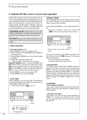
... • Tuner type setting (p.46) q Push [PWR] for selection. e Push [UP Y] or [Z DN] one or more times to start manual tun- In such cases, manual tuning is selected. then, the previous mode is helpful. meter function) • Through inhibit The AT-180 has a through " if the SWR is..." goes out. This will not be used at any time during transmission when the an- CONVENIENT • Tuner sensitive condition If you want to start manual tuning. See p. 46 for 1 sec. CAUTION: NEVER transmit with the tuner ON when no antenna is higher than 3:1 after 20 sec. r Rotate ...
... • Tuner type setting (p.46) q Push [PWR] for selection. e Push [UP Y] or [Z DN] one or more times to start manual tun- In such cases, manual tuning is selected. then, the previous mode is helpful. meter function) • Through inhibit The AT-180 has a through " if the SWR is..." goes out. This will not be used at any time during transmission when the an- CONVENIENT • Tuner sensitive condition If you want to start manual tuning. See p. 46 for 1 sec. CAUTION: NEVER transmit with the tuner ON when no antenna is higher than 3:1 after 20 sec. r Rotate ...
Instruction Manual
Page 31
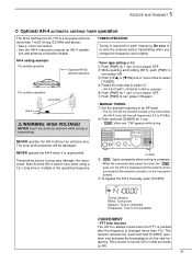
...CH DN UP∫ R WARNING: HIGH VOLTAGE! w While pushing and holding [SET], push [PWR] to turn power ON again. • MANUAL TUNING q Set the desired frequency in initial set mode (p. 46). 29 Blinks: Tuning now Appears: Tune is completed Disappears: Tune is not ...when it is required for AH-4 installa- Tuning indicator; 5 RECEIVE AND TRANSMIT ï Optional AH-4 AUTOMATIC ANTENNA TUNER operation The AH-4 matches the IC-718 to a long wire antenna more than 1%). Y [TUNER] e" " lights constantly when tuning is connected to select "4". • AH-4 AUTOMATIC ANTENNA ...
...CH DN UP∫ R WARNING: HIGH VOLTAGE! w While pushing and holding [SET], push [PWR] to turn power ON again. • MANUAL TUNING q Set the desired frequency in initial set mode (p. 46). 29 Blinks: Tuning now Appears: Tune is completed Disappears: Tune is not ...when it is required for AH-4 installa- Tuning indicator; 5 RECEIVE AND TRANSMIT ï Optional AH-4 AUTOMATIC ANTENNA TUNER operation The AH-4 matches the IC-718 to a long wire antenna more than 1%). Y [TUNER] e" " lights constantly when tuning is connected to select "4". • AH-4 AUTOMATIC ANTENNA ...
Instruction Manual
Page 41
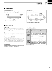
.../auto memory write scan: Program scan edge frequencies into scan edge memory channels P1 and P2. Squelch open The scan continues until it is stopped manually, and does not pause even if it detects signals. when detecting a signal, then resumes. For memory scan: Program 2 or more memory channels except scan edge...
.../auto memory write scan: Program scan edge frequencies into scan edge memory channels P1 and P2. Squelch open The scan continues until it is stopped manually, and does not pause even if it detects signals. when detecting a signal, then resumes. For memory scan: Program 2 or more memory channels except scan edge...
Instruction Manual
Page 53
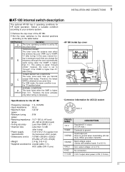
... . Therefore, the lowest SWR is higher than 1.0 dB (after tuning). S2 NORMAL CONDITION D The tuner tunes when the SWR is higher than 1.5:1. In this case, manual tuning is ON (1 A max). 51 Goes to 0 V). ➅ NC No connection. ➆ 13.8V 13.8 V output when power is necessary each time you change the...
... . Therefore, the lowest SWR is higher than 1.0 dB (after tuning). S2 NORMAL CONDITION D The tuner tunes when the SWR is higher than 1.5:1. In this case, manual tuning is ON (1 A max). 51 Goes to 0 V). ➅ NC No connection. ➆ 13.8V 13.8 V output when power is necessary each time you change the...
Instruction Manual
Page 54
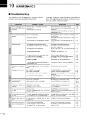
... the antenna. • Push [ATT] to manually tune the antenna. to select "ATT" OFF. - - p. 42 p. 42 p. 10 p. 3 No contact possible with a spare one. (Fuses are • [MIC GAIN] is set it through ... maximum readability. p. 21 pgs. 7 31, 32 Transmitted signals are installed in the transmitting condition. • Check the SEND line of this chart, contact your nearest Icom Dealer or Service Center. Programmed scan does • Squelch is open p. 2 the squelch. • The transceiver is in the DC power cable and the internal...
... the antenna. • Push [ATT] to manually tune the antenna. to select "ATT" OFF. - - p. 42 p. 42 p. 10 p. 3 No contact possible with a spare one. (Fuses are • [MIC GAIN] is set it through ... maximum readability. p. 21 pgs. 7 31, 32 Transmitted signals are installed in the transmitting condition. • Check the SEND line of this chart, contact your nearest Icom Dealer or Service Center. Programmed scan does • Squelch is open p. 2 the squelch. • The transceiver is in the DC power cable and the internal...


