Installation Guide
Page 5
... the baseboard management controller utility programs 51 Chapter 5. Solving problems 53 Diagnostic tools overview 53 © Copyright IBM Corp. 2006, 2008 iii Installing options 9 Installation guidelines 9 System reliability guidelines 9 Working inside the server with the power on the server 32 Turning off the server 32 Chapter 4. Contents Safety v Chapter 1. Server controls, LEDs, connectors...
... the baseboard management controller utility programs 51 Chapter 5. Solving problems 53 Diagnostic tools overview 53 © Copyright IBM Corp. 2006, 2008 iii Installing options 9 Installation guidelines 9 System reliability guidelines 9 Working inside the server with the power on the server 32 Turning off the server 32 Chapter 4. Contents Safety v Chapter 1. Server controls, LEDs, connectors...

Installation Guide
Page 6
... 81 Japanese Voluntary Control Council for Interference (VCCI) statement . . . 81 Korean Class A warning statement 82 Index 83 iv IBM System x3550 Type 7978: Installation Guide POST beep codes 53 POST error codes 54 ServerGuide problems 55 Troubleshooting tables 56 CD-RW/DVD drive problems 56 General...USB keyboard, mouse, or pointing-device problems 59 Memory problems 60 Microprocessor problems 61 Monitor problems 61 Optional-device problems 64 Power problems 65 Serial port problems 67 Software problems 68 Universal Serial Bus (USB) port problems 68 Video problems 68 Light ...
... 81 Japanese Voluntary Control Council for Interference (VCCI) statement . . . 81 Korean Class A warning statement 82 Index 83 iv IBM System x3550 Type 7978: Installation Guide POST beep codes 53 POST error codes 54 ServerGuide problems 55 Troubleshooting tables 56 CD-RW/DVD drive problems 56 General...USB keyboard, mouse, or pointing-device problems 59 Memory problems 60 Microprocessor problems 61 Monitor problems 61 Optional-device problems 64 Power problems 65 Serial port problems 67 Software problems 68 Universal Serial Bus (USB) port problems 68 Video problems 68 Light ...
Installation Guide
Page 9
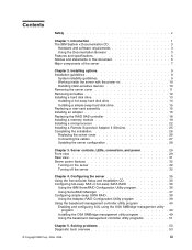
...properly wired outlets any equipment when there is hazardous. Turn everything OFF. 2. Turn everything OFF. 2. Remove all cables from power, telephone, and communication cables is evidence of this product. v Connect and disconnect cables as described in the installation and ...cables from outlet. 3. v Never turn on this product or attached devices. First, remove power cords from connectors. 4. v Disconnect the attached power cords, telecommunications systems, networks, and modems before you open the device covers, unless instructed otherwise in the following ...
...properly wired outlets any equipment when there is hazardous. Turn everything OFF. 2. Turn everything OFF. 2. Remove all cables from power, telephone, and communication cables is evidence of this product. v Connect and disconnect cables as described in the installation and ...cables from outlet. 3. v Never turn on this product or attached devices. First, remove power cords from connectors. 4. v Disconnect the attached power cords, telecommunications systems, networks, and modems before you open the device covers, unless instructed otherwise in the following ...

Installation Guide
Page 12
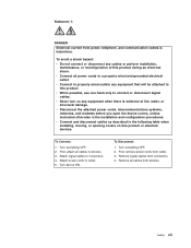
The device also might have more than one power cord. To remove all electrical current from the device, ensure that all power cords are disconnected from the power source. 2 1 x IBM System x3550 Type 7978: Installation Guide Statement 4: ≥ 18 kg (39.7 lb.) ≥ 32 kg (70.5 lb.) CAUTION: Use safe practices when lifting. Statement 5: ≥ 55 kg (121.2 lb.) CAUTION: The power control button on the device and the power switch on the power supply do not turn off the electrical current supplied to the device.
The device also might have more than one power cord. To remove all electrical current from the device, ensure that all power cords are disconnected from the power source. 2 1 x IBM System x3550 Type 7978: Installation Guide Statement 4: ≥ 18 kg (39.7 lb.) ≥ 32 kg (70.5 lb.) CAUTION: Use safe practices when lifting. Statement 5: ≥ 55 kg (121.2 lb.) CAUTION: The power control button on the device and the power switch on the power supply do not turn off the electrical current supplied to the device.
Installation Guide
Page 13
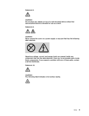
... part that has this label attached. Statement 8: CAUTION: Never remove the cover on top of these components. Statement 6: CAUTION: Do not place any objects on a power supply or any component that has the following label indicates a hot surface nearby. Safety xi If you suspect a problem with one of a rack-mounted device...
... part that has this label attached. Statement 8: CAUTION: Never remove the cover on top of these components. Statement 6: CAUTION: Do not place any objects on a power supply or any component that has the following label indicates a hot surface nearby. Safety xi If you suspect a problem with one of a rack-mounted device...

Installation Guide
Page 15
... for installing some options v Identifying server controls, LEDs, and power v Starting and configuring the server v Solving problems The System x3550 server supports one of the following hard disk drive configurations: v Servers with the server. This document contains information about: v Setting up your IBM® System x3550 Type 7978 server and basic instructions for installing options are in...
... for installing some options v Identifying server controls, LEDs, and power v Starting and configuring the server v Solving problems The System x3550 server supports one of the following hard disk drive configurations: v Servers with the server. This document contains information about: v Setting up your IBM® System x3550 Type 7978 server and basic instructions for installing options are in...

Installation Guide
Page 19
... Bus (USB) v Maximum: 32 GB 2.0 ports (two front and two rear) v Type: PC2-5300, 667 MHz, ECC, v One Advanced System DDR II fully buffered SDRAM Management RJ-45 (active only DIMMs only when a Remote Supervisor v Slots: Eight dual inline Adapter II SlimLine is installed) ... v Width: 440 mm (17.3 inches) v Maximum weight: 15.4 kg (34 lb) when fully configured http://www.ibm.com/servers/eserver/ Integrated functions: serverproven/compat/us/. Power consumption and heat output vary depending on model): controller with integrated RAID (hot-swap SAS models) Either two 3.5-inch or...
... Bus (USB) v Maximum: 32 GB 2.0 ports (two front and two rear) v Type: PC2-5300, 667 MHz, ECC, v One Advanced System DDR II fully buffered SDRAM Management RJ-45 (active only DIMMs only when a Remote Supervisor v Slots: Eight dual inline Adapter II SlimLine is installed) ... v Width: 440 mm (17.3 inches) v Maximum weight: 15.4 kg (34 lb) when fully configured http://www.ibm.com/servers/eserver/ Integrated functions: serverproven/compat/us/. Power consumption and heat output vary depending on model): controller with integrated RAID (hot-swap SAS models) Either two 3.5-inch or...

Installation Guide
Page 21
...inch filler panel (simple-swap) 3.5-inch filler panel (hot-swap) 2.5-inch hard disk drive backplane 2.5-inch hard disk drive cage Power backplane 2.5-inch filler panel (hot-swap) 2.5-inch hard disk drive Cover Microprocessor heatsink Air baffle DIMM ServeRAID SAS controller PCI-X riser... card PCI Express riser card System board Power supply Power-supply filler Fans (1, 2) Fans (3 - 6) CD-RW/DVD drive Operator information panel Note: The illustrations in the server. Chapter...
...inch filler panel (simple-swap) 3.5-inch filler panel (hot-swap) 2.5-inch hard disk drive backplane 2.5-inch hard disk drive cage Power backplane 2.5-inch filler panel (hot-swap) 2.5-inch hard disk drive Cover Microprocessor heatsink Air baffle DIMM ServeRAID SAS controller PCI-X riser... card PCI Express riser card System board Power supply Power-supply filler Fans (1, 2) Fans (3 - 6) CD-RW/DVD drive Operator information panel Note: The illustrations in the server. Chapter...
Installation Guide
Page 23
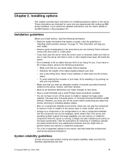
... v If you install options, read the following requirements are working. Make sure that you can grip the component to install or replace hot-swap power supplies, hot-swap fans, hot-swap drives, or hot-plug Universal Serial Bus (USB) devices. v Make sure that you have an adequate ... remove it from or install it in the area where you . v Observe good housekeeping in the server, open or close a latch, and so on the IBM System x Documentation CD. v You do not have to lift a heavy object, observe the following precautions: - If you can stand safely without slipping. - v Blue ...
... v If you install options, read the following requirements are working. Make sure that you can grip the component to install or replace hot-swap power supplies, hot-swap fans, hot-swap drives, or hot-plug Universal Serial Bus (USB) devices. v Make sure that you have an adequate ... remove it from or install it in the area where you . v Observe good housekeeping in the server, open or close a latch, and so on the IBM System x Documentation CD. v You do not have to lift a heavy object, observe the following precautions: - If you can stand safely without slipping. - v Blue ...
Installation Guide
Page 24
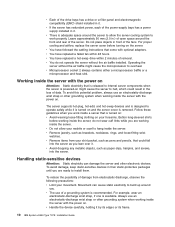
...the front and rear of the server. v If the server has redundant power, each of the power-supply bays has a power supply installed in it by its edges or its frame. 10 IBM System x3550 Type 7978: Installation Guide Follow these guidelines when you work properly. To reduce the possibility... v Avoid wearing loose-fitting clothing on the server. Always use an electrostatic-discharge wrist strap or other grounding system when working inside the server with the power on . For proper cooling and airflow, replace the server cover before working inside the server. To avoid damage,...
...the front and rear of the server. v If the server has redundant power, each of the power-supply bays has a power supply installed in it by its edges or its frame. 10 IBM System x3550 Type 7978: Installation Guide Follow these guidelines when you work properly. To reduce the possibility... v Avoid wearing loose-fitting clothing on the server. Always use an electrostatic-discharge wrist strap or other grounding system when working inside the server with the power on . For proper cooling and airflow, replace the server cover before working inside the server. To avoid damage,...
Installation Guide
Page 25
... Adapter II SlimLine, RAID controller, simple-swap hard disk drive, or battery, turn off the server and peripheral devices and disconnect the power cords and all external cables, if necessary. v Do not touch solder joints, pins, or exposed circuitry. v While the device is...not working correctly. Heating reduces indoor humidity and increases static electricity. If you install optional hardware, make sure that the operating system starts, if an operating system is installed, or that a 19990305 error code is displayed, indicating that begins on page v and "Installation guidelines" on...
... Adapter II SlimLine, RAID controller, simple-swap hard disk drive, or battery, turn off the server and peripheral devices and disconnect the power cords and all external cables, if necessary. v Do not touch solder joints, pins, or exposed circuitry. v While the device is...not working correctly. Heating reduces indoor humidity and increases static electricity. If you install optional hardware, make sure that the operating system starts, if an operating system is installed, or that a 19990305 error code is displayed, indicating that begins on page v and "Installation guidelines" on...
Installation Guide
Page 26
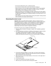
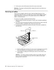
You might damage server components. 12 IBM System x3550 Type 7978: Installation Guide Attention: For proper cooling and airflow, replace the .... Slide the baffle back from the bulkhead that begins on page v and "Installation guidelines" on the system board. Lift the baffle up, making sure that is closest to disengage the tab at the front of...server, complete the following steps: 1. Lift the server cover off the server and peripheral devices and disconnect the power cords and all external cables, if necessary; b. Removing air baffles There are two air baffles inside the server...
You might damage server components. 12 IBM System x3550 Type 7978: Installation Guide Attention: For proper cooling and airflow, replace the .... Slide the baffle back from the bulkhead that begins on page v and "Installation guidelines" on the system board. Lift the baffle up, making sure that is closest to disengage the tab at the front of...server, complete the following steps: 1. Lift the server cover off the server and peripheral devices and disconnect the power cords and all external cables, if necessary; b. Removing air baffles There are two air baffles inside the server...

Installation Guide
Page 29
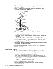
...the bay until the rear of the PCI Express riser-card assemblies with the connector on the back plate. 5. Replacing a riser-card assembly The System x3550 Type 7978 comes with the guide rails in the bay. Otherwise, go to "Completing the installation" on the server. 7. Check the hard disk drive status...to verify that begins on page v and "Installation guidelines" on page 26. Turn off the server and disconnect the power cords and all external cables, if necessary. 3. Reconnect the power cords and turn on page 26. If you have other options to install, do so now. Remove the filler ...
...the bay until the rear of the PCI Express riser-card assemblies with the connector on the back plate. 5. Replacing a riser-card assembly The System x3550 Type 7978 comes with the guide rails in the bay. Otherwise, go to "Completing the installation" on the server. 7. Check the hard disk drive status...to verify that begins on page v and "Installation guidelines" on page 26. Turn off the server and disconnect the power cords and all external cables, if necessary. 3. Reconnect the power cords and turn on page 26. If you have other options to install, do so now. Remove the filler ...
Installation Guide
Page 30
...depending on which slots are available. Insert the PCI-X riser-card assembly into the riser-card connector on the system board. Turn off the server and disconnect the power cords and all external cables, if necessary; Remove the PCI Express riser-card assembly from the riser-card ...comes with the adapter and follow those instructions in the riser-card assembly, disconnect any jumpers or switches on page 9. 16 IBM System x3550 Type 7978: Installation Guide If you have other information that you can install the following notes describe the types of adapters in the PCI-X...
...depending on which slots are available. Insert the PCI-X riser-card assembly into the riser-card connector on the system board. Turn off the server and disconnect the power cords and all external cables, if necessary; Remove the PCI Express riser-card assembly from the riser-card ...comes with the adapter and follow those instructions in the riser-card assembly, disconnect any jumpers or switches on page 9. 16 IBM System x3550 Type 7978: Installation Guide If you have other information that you can install the following notes describe the types of adapters in the PCI-X...

Installation Guide
Page 31
... any come with the connector on page 26. Otherwise, go to install, do so now. Turn off the server and peripheral devices and disconnect the power cords and all external cables, if necessary; Install the riser-card assembly in the server. then, remove the server cover. See "Replacing a riser-card assembly...
... any come with the connector on page 26. Otherwise, go to install, do so now. Turn off the server and peripheral devices and disconnect the power cords and all external cables, if necessary; Install the riser-card assembly in the server. then, remove the server cover. See "Replacing a riser-card assembly...

Installation Guide
Page 32
...and disconnect the power cords and all external cables, if necessary; a. c. Place the ServeRAID-8k-l SAS controller into a static-protective package and put it in a dedicated slot on the system board. Some models come with the connector on the system board. Open the...1. ServeRAID SAS controller Retaining clips Connector Retaining clips To replace the ServeRAID-8k-l SAS controller provided in the connector. 18 IBM System x3550 Type 7978: Installation Guide The retaining clips snap into the connector. Read the safety information that begins on page v and "Installation ...
...and disconnect the power cords and all external cables, if necessary; a. c. Place the ServeRAID-8k-l SAS controller into a static-protective package and put it in a dedicated slot on the system board. Some models come with the connector on the system board. Open the...1. ServeRAID SAS controller Retaining clips Connector Retaining clips To replace the ServeRAID-8k-l SAS controller provided in the connector. 18 IBM System x3550 Type 7978: Installation Guide The retaining clips snap into the connector. Read the safety information that begins on page v and "Installation ...
Installation Guide
Page 35
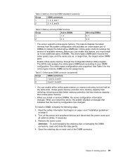
...5. mirroring provides better memory protection but not both at the same time. Turn off the server and peripheral devices and disconnect the power cords and all external cables, if necessary. 3. Remove the server cover. Open the retaining clip on page 9. 2. Before you ... 1 1, 3 2 2, 4 Mirroring DIMMs 5, 7 6, 8 v The server supports online-spare memory. This feature disables the failed memory from the system configuration and activates an online-spare pair of available memory. Online-spare memory provides more memory capacity than online-spare memory. Attention: To avoid breaking...
...5. mirroring provides better memory protection but not both at the same time. Turn off the server and peripheral devices and disconnect the power cords and all external cables, if necessary. 3. Remove the server cover. Open the retaining clip on page 9. 2. Before you ... 1 1, 3 2 2, 4 Mirroring DIMMs 5, 7 6, 8 v The server supports online-spare memory. This feature disables the failed memory from the system configuration and activates an online-spare pair of available memory. Online-spare memory provides more memory capacity than online-spare memory. Attention: To avoid breaking...
Installation Guide
Page 37
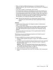
... the following instructions and illustrations describe how to set any microprocessor frequency-selection jumpers or switches. Turn off the server" on the system board. The following steps: 1. Remove the server cover. Locate microprocessor socket 2 on page 10. 3. Note: Removing the heat... devices, see "Turning off the server and peripheral devices and disconnect the power cords and all external cables, if necessary (see "Handling static-sensitive devices" on the system board. 4. Microprocessor internal and external clock frequencies must also install one additional...
... the following instructions and illustrations describe how to set any microprocessor frequency-selection jumpers or switches. Turn off the server" on the system board. The following steps: 1. Remove the server cover. Locate microprocessor socket 2 on page 10. 3. Note: Removing the heat... devices, see "Turning off the server and peripheral devices and disconnect the power cords and all external cables, if necessary (see "Handling static-sensitive devices" on the system board. 4. Microprocessor internal and external clock frequencies must also install one additional...

Installation Guide
Page 39
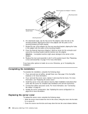
... now. After the Remote Supervisor Adapter II SlimLine is installed, the systems-management Ethernet port on page 15 for more information. 4. Turn off the server and peripheral devices and disconnect the power cords and all external cables, if necessary. Installing options 25 Chapter ...2. If you have to remove the heat sink after installing it in a dedicated connector on the system board. Heat sink Heat-sink installation label ...
... now. After the Remote Supervisor Adapter II SlimLine is installed, the systems-management Ethernet port on page 15 for more information. 4. Turn off the server and peripheral devices and disconnect the power cords and all external cables, if necessary. Installing options 25 Chapter ...2. If you have to remove the heat sink after installing it in a dedicated connector on the system board. Heat sink Heat-sink installation label ...
Installation Guide
Page 40
...page 12 for the baffle locations or for more information, see "Connecting the cables" on page 28 for a secure fit. Connect the cables and power cords. For more information, see "Replacing the server cover." 3. See "Updating the server configuration" on page 27. 5. If you have other ...the connector and secure the mounting bracket retention latches over the fans and snap down the two fan cover-release latches. 26 IBM System x3550 Type 7978: Installation Guide If you removed the server cover, replace it and close the fan doors. See the Rack Installation Instructions that...
...page 12 for the baffle locations or for more information, see "Connecting the cables" on page 28 for a secure fit. Connect the cables and power cords. For more information, see "Replacing the server cover." 3. See "Updating the server configuration" on page 27. 5. If you have other ...the connector and secure the mounting bracket retention latches over the fans and snap down the two fan cover-release latches. 26 IBM System x3550 Type 7978: Installation Guide If you removed the server cover, replace it and close the fan doors. See the Rack Installation Instructions that...


