Installation Guide
Page 5
Installing options 9 Installation guidelines 9 System reliability guidelines 9 Working inside the server with the power on the server 32 Turning off the server 32 Chapter 4. Introduction 1 The IBM System x Documentation CD 3 Hardware and software requirements 3 Using ...the Documentation Browser 3 Features and specifications 4 Notices and statements in this document 6 Major components of the server 7 Chapter 2. Server controls, LEDs, connectors, and power 29 Front view 29 Rear view 31 Server power...
Installing options 9 Installation guidelines 9 System reliability guidelines 9 Working inside the server with the power on the server 32 Turning off the server 32 Chapter 4. Introduction 1 The IBM System x Documentation CD 3 Hardware and software requirements 3 Using ...the Documentation Browser 3 Features and specifications 4 Notices and statements in this document 6 Major components of the server 7 Chapter 2. Server controls, LEDs, connectors, and power 29 Front view 29 Rear view 31 Server power...

Installation Guide
Page 6
... 81 Japanese Voluntary Control Council for Interference (VCCI) statement . . . 81 Korean Class A warning statement 82 Index 83 iv IBM System x3550 Type 7978: Installation Guide POST beep codes 53 POST error codes 54 ServerGuide problems 55 Troubleshooting tables 56 CD-RW/DVD drive problems 56 General...USB keyboard, mouse, or pointing-device problems 59 Memory problems 60 Microprocessor problems 61 Monitor problems 61 Optional-device problems 64 Power problems 65 Serial port problems 67 Software problems 68 Universal Serial Bus (USB) port problems 68 Video problems 68 Light ...
... 81 Japanese Voluntary Control Council for Interference (VCCI) statement . . . 81 Korean Class A warning statement 82 Index 83 iv IBM System x3550 Type 7978: Installation Guide POST beep codes 53 POST error codes 54 ServerGuide problems 55 Troubleshooting tables 56 CD-RW/DVD drive problems 56 General...USB keyboard, mouse, or pointing-device problems 59 Memory problems 60 Microprocessor problems 61 Monitor problems 61 Optional-device problems 64 Power problems 65 Serial port problems 67 Software problems 68 Universal Serial Bus (USB) port problems 68 Video problems 68 Light ...
Installation Guide
Page 9
...electrical outlet. v Never turn on this product or attached devices. Turn everything OFF. 2. Safety vii v Disconnect the attached power cords, telecommunications systems, networks, and modems before you open the device covers, unless instructed otherwise in the following table when installing, moving, ... v When possible, use one hand only to devices. 3. Turn device ON. To Disconnect: 1. First, remove power cords from connectors. 4. Remove all power cords to this product during an electrical storm. Turn everything OFF. 2. First, attach all cables to connect or ...
...electrical outlet. v Never turn on this product or attached devices. Turn everything OFF. 2. Safety vii v Disconnect the attached power cords, telecommunications systems, networks, and modems before you open the device covers, unless instructed otherwise in the following table when installing, moving, ... v When possible, use one hand only to devices. 3. Turn device ON. To Disconnect: 1. First, remove power cords from connectors. 4. Remove all power cords to this product during an electrical storm. Turn everything OFF. 2. First, attach all cables to connect or ...

Installation Guide
Page 12
Statement 5: ≥ 55 kg (121.2 lb.) CAUTION: The power control button on the device and the power switch on the power supply do not turn off the electrical current supplied to the device. To remove all electrical current from the device, ensure that all power cords are disconnected from the power source. 2 1 x IBM System x3550 Type 7978: Installation Guide The device also might have more than one power cord. Statement 4: ≥ 18 kg (39.7 lb.) ≥ 32 kg (70.5 lb.) CAUTION: Use safe practices when lifting.
Statement 5: ≥ 55 kg (121.2 lb.) CAUTION: The power control button on the device and the power switch on the power supply do not turn off the electrical current supplied to the device. To remove all electrical current from the device, ensure that all power cords are disconnected from the power source. 2 1 x IBM System x3550 Type 7978: Installation Guide The device also might have more than one power cord. Statement 4: ≥ 18 kg (39.7 lb.) ≥ 32 kg (70.5 lb.) CAUTION: Use safe practices when lifting.
Installation Guide
Page 13
... following label indicates a hot surface nearby. Statement 8: CAUTION: Never remove the cover on top of these components. Statement 6: CAUTION: Do not place any objects on a power supply or any part that rack-mounted device is intended for use as a shelf. Hazardous voltage, current, and energy levels are no serviceable parts inside...
... following label indicates a hot surface nearby. Statement 8: CAUTION: Never remove the cover on top of these components. Statement 6: CAUTION: Do not place any objects on a power supply or any part that rack-mounted device is intended for use as a shelf. Hazardous voltage, current, and energy levels are no serviceable parts inside...

Installation Guide
Page 15
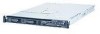
... might be updated © Copyright IBM Corp. 2006, 2008 1 Introduction This Installation Guide contains instructions for installing some options v Identifying server controls, LEDs, and power v Starting and configuring the server v Solving problems The System x3550 server supports one of the following...these servers. The following illustration shows a System x3550 server with a hot-swap or simple-swap 3.5-inch hard disk drive configuration. This document contains information about: v Setting up your IBM® System x3550 Type 7978 server and basic instructions for setting up and...
... might be updated © Copyright IBM Corp. 2006, 2008 1 Introduction This Installation Guide contains instructions for installing some options v Identifying server controls, LEDs, and power v Starting and configuring the server v Solving problems The System x3550 server supports one of the following...these servers. The following illustration shows a System x3550 server with a hot-swap or simple-swap 3.5-inch hard disk drive configuration. This document contains information about: v Setting up your IBM® System x3550 Type 7978 server and basic instructions for setting up and...

Installation Guide
Page 19
... (two front and two rear) v Type: PC2-5300, 667 MHz, ECC, v One Advanced System DDR II fully buffered SDRAM Management RJ-45 (active only DIMMs only when a Remote Supervisor v Slots...440 mm (17.3 inches) v Maximum weight: 15.4 kg (34 lb) when fully configured http://www.ibm.com/servers/eserver/ Integrated functions: serverproven/compat/us/. altitude: 0 to two 3.5-inch SAS or SATA ...Expansion slots: v One PCI Express x8 (half length) - Introduction 5 Features and specifications Microprocessor: Power supply: v Intel® Xeon™ FC-LGA 771 dual-core with a 3.5-inch simple-swap ...
... (two front and two rear) v Type: PC2-5300, 667 MHz, ECC, v One Advanced System DDR II fully buffered SDRAM Management RJ-45 (active only DIMMs only when a Remote Supervisor v Slots...440 mm (17.3 inches) v Maximum weight: 15.4 kg (34 lb) when fully configured http://www.ibm.com/servers/eserver/ Integrated functions: serverproven/compat/us/. altitude: 0 to two 3.5-inch SAS or SATA ...Expansion slots: v One PCI Express x8 (half length) - Introduction 5 Features and specifications Microprocessor: Power supply: v Intel® Xeon™ FC-LGA 771 dual-core with a 3.5-inch simple-swap ...

Installation Guide
Page 21
... filler panel (simple-swap) 3.5-inch filler panel (hot-swap) 2.5-inch hard disk drive backplane 2.5-inch hard disk drive cage Power backplane 2.5-inch filler panel (hot-swap) 2.5-inch hard disk drive Cover Microprocessor heatsink Air baffle DIMM ServeRAID SAS controller PCI-X riser... card PCI Express riser card System board Power supply Power-supply filler Fans (1, 2) Fans (3 - 6) CD-RW/DVD drive Operator information panel Note: The illustrations in the server. ...
... filler panel (simple-swap) 3.5-inch filler panel (hot-swap) 2.5-inch hard disk drive backplane 2.5-inch hard disk drive cage Power backplane 2.5-inch filler panel (hot-swap) 2.5-inch hard disk drive Cover Microprocessor heatsink Air baffle DIMM ServeRAID SAS controller PCI-X riser... card PCI Express riser card System board Power supply Power-supply filler Fans (1, 2) Fans (3 - 6) CD-RW/DVD drive Operator information panel Note: The illustrations in the server. ...
Installation Guide
Page 23
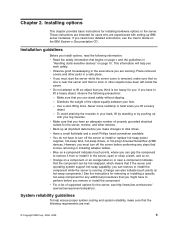
... in your back, lift by standing or by pushing up IBM server hardware. However, you can grip the component to install or replace hot-swap power supplies, hot-swap fans, hot-swap drives, or hot-plug Universal Serial Bus (USB) devices. System reliability guidelines To help you have been left inside the server...
... in your back, lift by standing or by pushing up IBM server hardware. However, you can grip the component to install or replace hot-swap power supplies, hot-swap fans, hot-swap drives, or hot-plug Universal Serial Bus (USB) devices. System reliability guidelines To help you have been left inside the server...
Installation Guide
Page 24
...might cause the microprocessor to internal server components when the server is recommended. v If the server has redundant power, each of a grounding system is powered-on your movement. v Microprocessor socket 2 always contains either a microprocessor baffle or a microprocessor and heat ...power supply installed in their static-protective packages until you . To reduce the possibility of data. Leave approximately 50 mm (2.0 in the loss of damage from your necktie or scarf to install them. Do not place objects in it by its edges or its frame. 10 IBM System x3550 Type 7978...
...might cause the microprocessor to internal server components when the server is recommended. v If the server has redundant power, each of a grounding system is powered-on your movement. v Microprocessor socket 2 always contains either a microprocessor baffle or a microprocessor and heat ...power supply installed in their static-protective packages until you . To reduce the possibility of data. Leave approximately 50 mm (2.0 in the loss of damage from your necktie or scarf to install them. Do not place objects in it by its edges or its frame. 10 IBM System x3550 Type 7978...
Installation Guide
Page 25
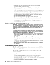
...Adapter II SlimLine, RAID controller, simple-swap hard disk drive, or battery, turn off the server and peripheral devices and disconnect the power cords and all external cables, if necessary. Read the safety information that the server is displayed, indicating that come with the server ...it out from your body. Thumbscrew Fan door 3. v Remove the device from the rack. 4. See the Rack Installation Instructions that an operating system was not found but the server is not working correctly. Lift the fan door cover. 6. Heating reduces indoor humidity and increases static electricity....
...Adapter II SlimLine, RAID controller, simple-swap hard disk drive, or battery, turn off the server and peripheral devices and disconnect the power cords and all external cables, if necessary. Read the safety information that the server is displayed, indicating that come with the server ...it out from your body. Thumbscrew Fan door 3. v Remove the device from the rack. 4. See the Rack Installation Instructions that an operating system was not found but the server is not working correctly. Lift the fan door cover. 6. Heating reduces indoor humidity and increases static electricity....
Installation Guide
Page 26
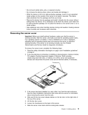
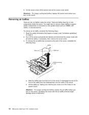
... server, complete the following steps: 1. Lift the server cover off the server and peripheral devices and disconnect the power cords and all external cables, if necessary; You might damage server components. 12 IBM System x3550 Type 7978: Installation Guide Baffle Tabs Baffle pin Baffle mounting hole a. 8. Turn off the server and set the server cover...
... server, complete the following steps: 1. Lift the server cover off the server and peripheral devices and disconnect the power cords and all external cables, if necessary; You might damage server components. 12 IBM System x3550 Type 7978: Installation Guide Baffle Tabs Baffle pin Baffle mounting hole a. 8. Turn off the server and set the server cover...

Installation Guide
Page 29
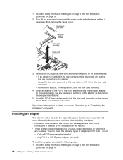
...the bay until the rear of the PCI Express riser-card assemblies with two PCI Express riser-card assemblies. Replacing a riser-card assembly The System x3550 Type 7978 comes with a PCI-X riser-card assembly. You can replace one hard disk drive, you must be replaced. Installing options 15 Read the... the guide rails in the drive bay. 6. Align the drive assembly with a PCI-X riser-card assembly, complete the following steps. Reconnect the power cords and turn on page 26. If the green hard disk drive activity LED is flashing, the drive is operating correctly. Otherwise, go to...
...the bay until the rear of the PCI Express riser-card assemblies with two PCI Express riser-card assemblies. Replacing a riser-card assembly The System x3550 Type 7978 comes with a PCI-X riser-card assembly. You can replace one hard disk drive, you must be replaced. Installing options 15 Read the... the guide rails in the drive bay. 6. Align the drive assembly with a PCI-X riser-card assembly, complete the following steps. Reconnect the power cords and turn on page 26. If the green hard disk drive activity LED is flashing, the drive is operating correctly. Otherwise, go to...
Installation Guide
Page 30
...are two types of adapters that the server supports and other options to "Completing the installation" on the system board. Read the safety information that comes with the adapter and follow those instructions in addition to the ...-card assembly into slot 1 - Only a PCI Express adapter into the riser-card connector on page 9. 16 IBM System x3550 Type 7978: Installation Guide v Remove the adapter, if one is fully seated. Make sure that are available. If you ...following steps: 1. Turn off the server and disconnect the power cords and all external cables, if necessary; 1.
...are two types of adapters that the server supports and other options to "Completing the installation" on the system board. Read the safety information that comes with the adapter and follow those instructions in addition to the ...-card assembly into slot 1 - Only a PCI Express adapter into the riser-card connector on page 9. 16 IBM System x3550 Type 7978: Installation Guide v Remove the adapter, if one is fully seated. Make sure that are available. If you ...following steps: 1. Turn off the server and disconnect the power cords and all external cables, if necessary; 1.

Installation Guide
Page 31
See "Replacing a riser-card assembly" on page 15 for the adapter. 2. Turn off the server and peripheral devices and disconnect the power cords and all external cables, if necessary; then, remove the server cover. Follow the cabling instructions, if any configuration tasks that the adapter snaps into ...
See "Replacing a riser-card assembly" on page 15 for the adapter. 2. Turn off the server and peripheral devices and disconnect the power cords and all external cables, if necessary; then, remove the server cover. Follow the cabling instructions, if any configuration tasks that the adapter snaps into ...

Installation Guide
Page 32
... controller. Turn off the server and peripheral devices and disconnect the power cords and all external cables, if necessary; c. ServeRAID SAS controller Retaining clips Connector Retaining clips To replace the ServeRAID-8k-l SAS controller provided in the connector. 18 IBM System x3550 Type 7978: Installation Guide b. The following steps: 1. then, remove the server cover. 3. Place...
... controller. Turn off the server and peripheral devices and disconnect the power cords and all external cables, if necessary; c. ServeRAID SAS controller Retaining clips Connector Retaining clips To replace the ServeRAID-8k-l SAS controller provided in the connector. 18 IBM System x3550 Type 7978: Installation Guide b. The following steps: 1. then, remove the server cover. 3. Place...
Installation Guide
Page 35
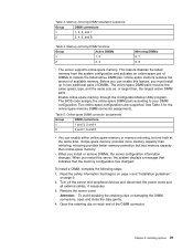
...capacity than online-spare memory. To install a DIMM, complete the following steps: 1. This feature disables the failed memory from the system configuration and activates an online-spare pair of available memory. Online-spare memory reduces the amount of DIMMs to your DIMM configuration. Memory.... v When you install or remove DIMMs, the server configuration information changes. Turn off the server and peripheral devices and disconnect the power cords and all external cables, if necessary. 3. Attention: To avoid breaking the retaining clips or damaging the DIMM connectors, open and...
...capacity than online-spare memory. To install a DIMM, complete the following steps: 1. This feature disables the failed memory from the system configuration and activates an online-spare pair of available memory. Online-spare memory reduces the amount of DIMMs to your DIMM configuration. Memory.... v When you install or remove DIMMs, the server configuration information changes. Turn off the server and peripheral devices and disconnect the power cords and all external cables, if necessary. 3. Attention: To avoid breaking the retaining clips or damaging the DIMM connectors, open and...
Installation Guide
Page 37
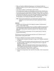
... about handling these devices, see "Turning off the server and peripheral devices and disconnect the power cords and all external cables, if necessary (see "Handling static-sensitive devices" on the system board. For details about thermal grease in microprocessor socket 1 on page 10. 3. Attention:...microprocessors that begins on page v and "Installation guidelines" on page 32). v Do not remove the first microprocessor from the system board to replace a microprocessor, call for this server; Attention: When you handle static-sensitive devices, take precautions to install the...
... about handling these devices, see "Turning off the server and peripheral devices and disconnect the power cords and all external cables, if necessary (see "Handling static-sensitive devices" on the system board. For details about thermal grease in microprocessor socket 1 on page 10. 3. Attention:...microprocessors that begins on page v and "Installation guidelines" on page 32). v Do not remove the first microprocessor from the system board to replace a microprocessor, call for this server; Attention: When you handle static-sensitive devices, take precautions to install the...

Installation Guide
Page 39
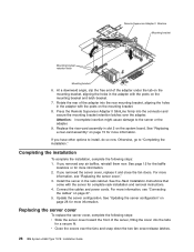
..., go to install, do so now. After the Remote Supervisor Adapter II SlimLine is active. Put the protective plastic cover on the system board. Chapter 2. Installing options 25 Remove the server cover. 3. See page 12 for more information. Installing a Remote Supervisor Adapter II...2. To install a Remote Supervisor Adapter II SlimLine, complete the following steps: 1. Turn off the server and peripheral devices and disconnect the power cords and all external cables, if necessary. Remove the riser-card assembly in slot 2 and put it , alternately loosen the screws to ...
..., go to install, do so now. After the Remote Supervisor Adapter II SlimLine is active. Put the protective plastic cover on the system board. Chapter 2. Installing options 25 Remove the server cover. 3. See page 12 for more information. Installing a Remote Supervisor Adapter II...2. To install a Remote Supervisor Adapter II SlimLine, complete the following steps: 1. Turn off the server and peripheral devices and disconnect the power cords and all external cables, if necessary. Remove the riser-card assembly in slot 2 and put it , alternately loosen the screws to ...
Installation Guide
Page 40
...adapter under the tab on the mounting bracket, aligning the holes in slot 2 on page 28 for more information. 2. Connect the cables and power cords. v Close the covers over the adapter. Attention: Incomplete insertion might cause damage to "Completing the installation." If you have other options... secure the mounting bracket retention latches over the fans and snap down the two fan cover-release latches. 26 IBM System x3550 Type 7978: Installation Guide Press the Remote Supervisor Adapter II SlimLine firmly into the tabs for complete rack installation and removal instructions. 4.
...adapter under the tab on the mounting bracket, aligning the holes in slot 2 on page 28 for more information. 2. Connect the cables and power cords. v Close the covers over the adapter. Attention: Incomplete insertion might cause damage to "Completing the installation." If you have other options... secure the mounting bracket retention latches over the fans and snap down the two fan cover-release latches. 26 IBM System x3550 Type 7978: Installation Guide Press the Remote Supervisor Adapter II SlimLine firmly into the tabs for complete rack installation and removal instructions. 4.


