
User Guide
Page 18
...User Guide Internal drives v 3.5-inch, 1.44 MB diskette drive v Internal hard disk drive v EIDE CD-ROM drive or DVD-ROM drive (some models) Video subsystem v An integrated graphics controller for a Video Graphics Array (VGA) monitor v Accelerated graphics port (AGP) video adapter slot on the system board Audio subsystem v AC'97 with ADI 1981B Audio Codec v Line in, line out, and microphone connectors on the rear panel Connectivity v 10/100 Mbps integrated Intel Ethernet controller that supports the Wake on LAN® feature (some models) v 10/100/1000 Mbps integrated Intel Ethernet controller...
...User Guide Internal drives v 3.5-inch, 1.44 MB diskette drive v Internal hard disk drive v EIDE CD-ROM drive or DVD-ROM drive (some models) Video subsystem v An integrated graphics controller for a Video Graphics Array (VGA) monitor v Accelerated graphics port (AGP) video adapter slot on the system board Audio subsystem v AC'97 with ADI 1981B Audio Codec v Line in, line out, and microphone connectors on the rear panel Connectivity v 10/100 Mbps integrated Intel Ethernet controller that supports the Wake on LAN® feature (some models) v 10/100/1000 Mbps integrated Intel Ethernet controller...
User Guide
Page 22
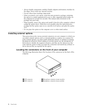
... the option on the computer cover or other unpainted metal surface on it directly in the package and your computer The following illustration shows the locations of the computer. 1 USB connector 2 USB connector 3 Microphone connector (some models) 4 Headphone connector (some external options, you install a new option, touch the static-protective package containing the option to making the physical connection. Handle adapters and memory modules by the edges. For some models) 6 User Guide v Always...
... the option on the computer cover or other unpainted metal surface on it directly in the package and your computer The following illustration shows the locations of the computer. 1 USB connector 2 USB connector 3 Microphone connector (some models) 4 Headphone connector (some external options, you install a new option, touch the static-protective package containing the option to making the physical connection. Handle adapters and memory modules by the edges. For some models) 6 User Guide v Always...
User Guide
Page 40
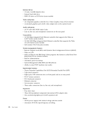
24 User Guide Internal drives v 3.5-inch, 1.44 MB diskette drive v Internal hard disk drive v EIDE CD drive or DVD drive (some models) Video subsystem v An integrated graphics controller for a Video Graphics Array (VGA) monitor v Accelerated graphics port (AGP) video adapter slot on the system board Audio subsystem v AC'97 with ADI 1981B Audio Codec v Line in, line out, and microphone connectors on the rear panel Connectivity v 10/100 Mbps integrated Intel Ethernet controller that supports the Wake on LAN® feature (some models) v 10/100/1000 Mbps integrated Intel Ethernet controller that...
24 User Guide Internal drives v 3.5-inch, 1.44 MB diskette drive v Internal hard disk drive v EIDE CD drive or DVD drive (some models) Video subsystem v An integrated graphics controller for a Video Graphics Array (VGA) monitor v Accelerated graphics port (AGP) video adapter slot on the system board Audio subsystem v AC'97 with ADI 1981B Audio Codec v Line in, line out, and microphone connectors on the rear panel Connectivity v 10/100 Mbps integrated Intel Ethernet controller that supports the Wake on LAN® feature (some models) v 10/100/1000 Mbps integrated Intel Ethernet controller that...
User Guide
Page 64
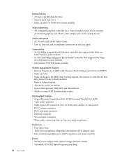
48 User Guide Internal drives v 3.5-inch, 1.44 MB diskette drive v Internal hard disk drive v EIDE CD drive or DVD drive (some models) Video subsystem v An integrated graphics controller for a Video Graphics Array (VGA) monitor v Accelerated graphics port (AGP) video adapter slot on the system board Audio subsystem v AC'97 with ADI 1981B Audio Codec v Line in, line out, and microphone connectors on the rear panel Connectivity v 10/100 Mbps integrated Intel Ethernet controller that supports the Wake on LAN® feature (some models) v 10/100/1000 Mbps integrated Intel Ethernet controller that...
48 User Guide Internal drives v 3.5-inch, 1.44 MB diskette drive v Internal hard disk drive v EIDE CD drive or DVD drive (some models) Video subsystem v An integrated graphics controller for a Video Graphics Array (VGA) monitor v Accelerated graphics port (AGP) video adapter slot on the system board Audio subsystem v AC'97 with ADI 1981B Audio Codec v Line in, line out, and microphone connectors on the rear panel Connectivity v 10/100 Mbps integrated Intel Ethernet controller that supports the Wake on LAN® feature (some models) v 10/100/1000 Mbps integrated Intel Ethernet controller that...

User Guide
Page 86
... access to remove any cables, including telephone lines and power cords. Move the jumper back to the maintenance or configure position (pins 2 and 3). 6. Replace the cover and connect the power cord. Remove the cover. See "Replacing the cover and connecting the cables." 7. Replacing the cover and connecting the cables After working with options, you might impede the replacement of the cover. 70 User Guide To replace the cover and connect cables to confirm the updated information in the IBM Setup Utility program. Ensure that all attached devices...
... access to remove any cables, including telephone lines and power cords. Move the jumper back to the maintenance or configure position (pins 2 and 3). 6. Replace the cover and connect the power cord. Remove the cover. See "Replacing the cover and connecting the cables." 7. Replacing the cover and connecting the cables After working with options, you might impede the replacement of the cover. 70 User Guide To replace the cover and connect cables to confirm the updated information in the IBM Setup Utility program. Ensure that all attached devices...
User Guide
Page 90
v 512 KB flash memory for system programs Internal drives v 3.5-inch, 1.44 MB diskette drive v Internal hard disk drive v EIDE CD drive or DVD drive Video subsystem v An integrated graphics controller for a Video Graphics Array (VGA) monitor v Accelerated graphics port (AGP) video adapter slot on the system board Audio subsystem v AC'97 with ADI 1981B Audio Codec v Line in, line out, and microphone connectors on the rear panel Connectivity v 10/100 Mbps integrated Intel Ethernet controller that supports the Wake on LAN® feature (some models) v 10/100/1000 Mbps...
v 512 KB flash memory for system programs Internal drives v 3.5-inch, 1.44 MB diskette drive v Internal hard disk drive v EIDE CD drive or DVD drive Video subsystem v An integrated graphics controller for a Video Graphics Array (VGA) monitor v Accelerated graphics port (AGP) video adapter slot on the system board Audio subsystem v AC'97 with ADI 1981B Audio Codec v Line in, line out, and microphone connectors on the rear panel Connectivity v 10/100 Mbps integrated Intel Ethernet controller that supports the Wake on LAN® feature (some models) v 10/100/1000 Mbps...

User Guide
Page 116
... access the IBM Setup Utility program. Setting, changing, and deleting a password To set to Disable, all diskettes are treated as hard disk drives or the CD-ROM drive) are disabled and will see "Starting the IBM Setup Utility program" on page 99). 2. If you type the wrong password, you must turn the computer off and start again. Start the IBM Setup Utility program (see an error message. If you might want to set Security Profile by Device. 4. From the IBM Setup Utility program menu...
... access the IBM Setup Utility program. Setting, changing, and deleting a password To set to Disable, all diskettes are treated as hard disk drives or the CD-ROM drive) are disabled and will see "Starting the IBM Setup Utility program" on page 99). 2. If you type the wrong password, you must turn the computer off and start again. Start the IBM Setup Utility program (see an error message. If you might want to set Security Profile by Device. 4. From the IBM Setup Utility program menu...

User Guide
Page 117
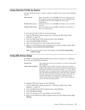
... IDE Drives Setup. 4. Then the serial ATA drive will operate in ″native″ mode. Start the IBM Setup Utility program (see the prompt. 3. Select the desired devices and settings and press Enter. 5. Turn off your computer and look for configuring the serial and parallel IDE controllers. Select the desired startup device from the Alternate startup devices menu does not permanently change the primary or automatic power-on page 99). 2. Note: Selecting a startup device from the Startup Device menu...
... IDE Drives Setup. 4. Then the serial ATA drive will operate in ″native″ mode. Start the IBM Setup Utility program (see the prompt. 3. Select the desired devices and settings and press Enter. 5. Turn off your computer and look for configuring the serial and parallel IDE controllers. Select the desired startup device from the Alternate startup devices menu does not permanently change the primary or automatic power-on page 99). 2. Note: Selecting a startup device from the Startup Device menu...
User Guide
Page 118
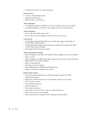
... screen. 4. Advanced settings On some computer models, the Advanced settings menu includes a setting to the default settings, select Load Default Settings on the Exit menu. Select Exit from the IBM Setup Utility menu and then Save Settings. The default setting for the Primary Startup Sequence, the Automatic Startup Sequence, and the Error Startup Sequence. 5. Select Startup Sequence. See the information displayed on page 99). 2. This feature works only with HyperThreading-aware operating systems such as Microsoft Windows...
... screen. 4. Advanced settings On some computer models, the Advanced settings menu includes a setting to the default settings, select Load Default Settings on the Exit menu. Select Exit from the IBM Setup Utility menu and then Save Settings. The default setting for the Primary Startup Sequence, the Automatic Startup Sequence, and the Error Startup Sequence. 5. Select Startup Sequence. See the information displayed on page 99). 2. This feature works only with HyperThreading-aware operating systems such as Microsoft Windows...
User Guide
Page 120
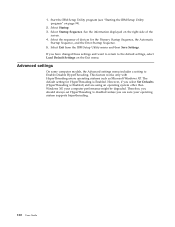
.... 14. Locate the Clear CMOS/Recovery jumper on the system board. If necessary, refer to Installing adapters to the list of beeps will be no video and the series of files. Move the jumper from a POST/BIOS update failure If power to electrical outlets. 8. Replace the cover. Unplug the power cords from electrical outlets, and remove the cover. Remove the cover. Replace any cables that were disconnected. 16. Replace the cover and reconnect any adapters that impede access to pins 2 and...
.... 14. Locate the Clear CMOS/Recovery jumper on the system board. If necessary, refer to Installing adapters to the list of beeps will be no video and the series of files. Move the jumper from a POST/BIOS update failure If power to electrical outlets. 8. Replace the cover. Unplug the power cords from electrical outlets, and remove the cover. Remove the cover. Replace any cables that were disconnected. 16. Replace the cover and reconnect any adapters that impede access to pins 2 and...
User Guide
Page 126
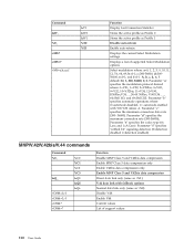
..., 64, 69; c=300-56000; and f=0-1. Parameter ″b″ specifies automode operations where: 0=automode disabled, 1= automode enabled with fallback options Normal data link only (same as Profile 1 Disable auto-retrain Enable auto-retrain Displays the current Select Modulation settings Displays a list of support values 110 User Guide Parameter ″d″ specifies the maximum connection rate (300-56000); b=0-1; d=30056000; Parameter ″a″ specifies the modulation protocol...
..., 64, 69; c=300-56000; and f=0-1. Parameter ″b″ specifies automode operations where: 0=automode disabled, 1= automode enabled with fallback options Normal data link only (same as Profile 1 Disable auto-retrain Enable auto-retrain Displays the current Select Modulation settings Displays a list of support values 110 User Guide Parameter ″d″ specifies the maximum connection rate (300-56000); b=0-1; d=30056000; Parameter ″a″ specifies the modulation protocol...
Hardware Maintenance Manual
Page 9
...Support for four dual inline memory modules (DIMMs) v 512 KB flash memory for system programs Internal drives v 3.5-inch, 1.44 MB diskette drive v Internal hard disk drive v EIDE CD-ROM drive or DVD-ROM drive (some models) Video subsystem v An integrated graphics controller for a Video Graphics Array (VGA) monitor v Accelerated graphics port (AGP) video adapter slot on the system board Audio subsystem v AC'97 with ADI 1981B Audio Codec v Line in, line out, and microphone connectors on the rear panel Connectivity v 10/100/1000 Mbps integrated Intel Ethernet controller that supports the Wake...
...Support for four dual inline memory modules (DIMMs) v 512 KB flash memory for system programs Internal drives v 3.5-inch, 1.44 MB diskette drive v Internal hard disk drive v EIDE CD-ROM drive or DVD-ROM drive (some models) Video subsystem v An integrated graphics controller for a Video Graphics Array (VGA) monitor v Accelerated graphics port (AGP) video adapter slot on the system board Audio subsystem v AC'97 with ADI 1981B Audio Codec v Line in, line out, and microphone connectors on the rear panel Connectivity v 10/100/1000 Mbps integrated Intel Ethernet controller that supports the Wake...
Hardware Maintenance Manual
Page 17
... 4, "IBM Enhanced Diagnostics," on the system. Set Power-On Self-Test to properly determine if a test Passed, Failed or Aborted, the test programs check the error-return code at test completion. General error messages appear if a problem or conflict is something wrong with a hardware option. The following : 1. Factory Contents - Error Code Format v IBM Enhanced Diagnostics program v Product recovery utility - Notes: v By default, the computer starts up quiet (no beep and no memory count and checkpoint code display...
... 4, "IBM Enhanced Diagnostics," on the system. Set Power-On Self-Test to properly determine if a test Passed, Failed or Aborted, the test programs check the error-return code at test completion. General error messages appear if a problem or conflict is something wrong with a hardware option. The following : 1. Factory Contents - Error Code Format v IBM Enhanced Diagnostics program v Product recovery utility - Notes: v By default, the computer starts up quiet (no beep and no memory count and checkpoint code display...
Hardware Maintenance Manual
Page 27
... devices and settings and press Enter. 5. Parallel ATA Native Mode Operation This setting allows the user to Disable, all diskettes are treated as hard disk drives or the CD-ROM drive) are options for configuring the serial and parallel IDE controllers. Start the IBM Setup Utility program (see "Starting the IBM Setup Utility program" on page 19). 2. IBM Setup Utility program 21 When this feature is present. Using IDE Drives Setup In addition to Disable, the diskette drive cannot be displayed in the system configuration...
... devices and settings and press Enter. 5. Parallel ATA Native Mode Operation This setting allows the user to Disable, all diskettes are treated as hard disk drives or the CD-ROM drive) are options for configuring the serial and parallel IDE controllers. Start the IBM Setup Utility program (see "Starting the IBM Setup Utility program" on page 19). 2. IBM Setup Utility program 21 When this feature is present. Using IDE Drives Setup In addition to Disable, the diskette drive cannot be displayed in the system configuration...
Hardware Maintenance Manual
Page 70
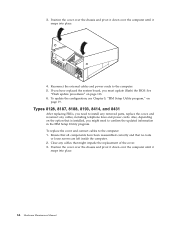
... 8431 After replacing FRUs, you need to install any removed parts, replace the cover, and reconnect any cables that is installed, you must update (flash) the BIOS. Also, depending on the option that might impede the replacement of the cover. 3. Position the cover over the chassis and pivot it down over the computer until it snaps into place. 64 Hardware Maintenance Manual Clear any cables, including telephone lines and power cords. Ensure...
... 8431 After replacing FRUs, you need to install any removed parts, replace the cover, and reconnect any cables that is installed, you must update (flash) the BIOS. Also, depending on the option that might impede the replacement of the cover. 3. Position the cover over the chassis and pivot it down over the computer until it snaps into place. 64 Hardware Maintenance Manual Clear any cables, including telephone lines and power cords. Ensure...

Hardware Maintenance Manual
Page 100
... 1. Covers were removed from the computer System Board System Board System Board 1. Enter the administrator password 1. Run Setup. Clear Administration password 2. Check to access the computer System Board System Board System Board System Board System Board System Board System Board 94 Hardware Maintenance Manual Check Stepping level for the BIOS level needed, then perform the flash update. 2. Make sure Asset Care and Asset ID are enabled. 2. Processor 1. System Board 1. System Board Set configuration and reinstall the boot sequence System Board 1. POST Error Code 167...
... 1. Covers were removed from the computer System Board System Board System Board 1. Enter the administrator password 1. Run Setup. Clear Administration password 2. Check to access the computer System Board System Board System Board System Board System Board System Board System Board 94 Hardware Maintenance Manual Check Stepping level for the BIOS level needed, then perform the flash update. 2. Make sure Asset Care and Asset ID are enabled. 2. Processor 1. System Board 1. System Board Set configuration and reinstall the boot sequence System Board 1. POST Error Code 167...
Hardware Maintenance Manual
Page 114
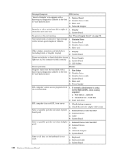
...disk error-type message with a known-good diagnostics diskette in the first 3.5-inch diskette drive. 1. Diskette Drive Cable 4. Power Supply light not on page 70. System Board 5. Power Supply RPL computer cannot access programs from left to right of 1. Check startup sequence 2. port) 2. Keyboard 2. Keyboard Cable 3. Display characters and color bars 2. System Board No power or fan not running See "Power Supply Errors" on , but computer works correctly 2. Check the network adapter LED status Serial or parallel port device failure (system board port) 1. External...
...disk error-type message with a known-good diagnostics diskette in the first 3.5-inch diskette drive. 1. Diskette Drive Cable 4. Power Supply light not on page 70. System Board 5. Power Supply RPL computer cannot access programs from left to right of 1. Check startup sequence 2. port) 2. Keyboard 2. Keyboard Cable 3. Display characters and color bars 2. System Board No power or fan not running See "Power Supply Errors" on , but computer works correctly 2. Check the network adapter LED status Serial or parallel port device failure (system board port) 1. External...

Hardware Maintenance Manual
Page 117
... IBM Setup Utility program. Refer to enter a new password when service is activated, and you do not enter the administrator password, the configuration can be viewed but not changed. © Copyright IBM Corp. 2005 111 Reset the date and time and remind the user to "Identifying parts on the system board (all machine types)" on and Administrator passwords are set in the Setup Utility program. If the administrator password is complete. Chapter 8. Removing a power-on password...
... IBM Setup Utility program. Refer to enter a new password when service is activated, and you do not enter the administrator password, the configuration can be viewed but not changed. © Copyright IBM Corp. 2005 111 Reset the date and time and remind the user to "Identifying parts on the system board (all machine types)" on and Administrator passwords are set in the Setup Utility program. If the administrator password is complete. Chapter 8. Removing a power-on password...
Hardware Maintenance Manual
Page 120
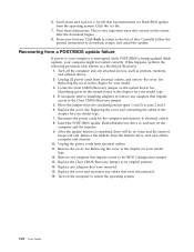
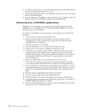
... to return to the list of short beeps. Return the boot block recovery jumper to continue. 14. Select the desired language from a POST/BIOS update failure Attention: If an interruption occurs during a Flash/BIOS upgrade, the BIOS might be followed by plugging in the floppy disk drive. 9. Enter the Machine Type and model number of the system and press Enter. 12. If a prompt appears stating that has instructions for approximately ten seconds...
... to return to the list of short beeps. Return the boot block recovery jumper to continue. 14. Select the desired language from a POST/BIOS update failure Attention: If an interruption occurs during a Flash/BIOS upgrade, the BIOS might be followed by plugging in the floppy disk drive. 9. Enter the Machine Type and model number of the system and press Enter. 12. If a prompt appears stating that has instructions for approximately ten seconds...

Hardware Maintenance Manual
Page 236
... 37L5098 59P8571 59P8572 59P8564 32P4743 22P4447 09N5764 75H9219 03K9655 59P8543 59P8549 49P4365 59P8545 49P1933 59P8587 230 Hardware Maintenance Manual CRU * * ** ** N N N CRU hardware kit (all models) Cable, CDROM audio (all models) Rubber foot (all models) Hard disk drive bracket assembly (all models) Hard disk drive tray (dampened) (all models) Cable, dual USB 2.0 (all models) Control panel assembly (all models) Audio cable assembly (ATA) (all models) PCMCIA assembly (all models) Fan assembly, 80 mm, fixed speed (models with 3.06GHz microprocessor or greater) Misc.
... 37L5098 59P8571 59P8572 59P8564 32P4743 22P4447 09N5764 75H9219 03K9655 59P8543 59P8549 49P4365 59P8545 49P1933 59P8587 230 Hardware Maintenance Manual CRU * * ** ** N N N CRU hardware kit (all models) Cable, CDROM audio (all models) Rubber foot (all models) Hard disk drive bracket assembly (all models) Hard disk drive tray (dampened) (all models) Cable, dual USB 2.0 (all models) Control panel assembly (all models) Audio cable assembly (ATA) (all models) PCMCIA assembly (all models) Fan assembly, 80 mm, fixed speed (models with 3.06GHz microprocessor or greater) Misc.


