
Hardware Maintenance Manual
Page 5
...17 Quick and Full erase - desktop model . . . 10 Physical specifications - Replacing FRUs 27 small desktop models 27 Locating components 27 Identifying parts on the system board . . . . 28 Removing the cover 28 Replacing the microprocessor 29 Replacing the power supply 30 Replacing the system board... 30 Replacing the speaker 32 Desktop models 32 Locating components 33 © Copyright IBM Corp. 2004 Identifying parts on the system board . . . . 33 Removing the cover 34 Replacing the microprocessor 35 Replacing the power supply 35 ...
...17 Quick and Full erase - desktop model . . . 10 Physical specifications - Replacing FRUs 27 small desktop models 27 Locating components 27 Identifying parts on the system board . . . . 28 Removing the cover 28 Replacing the microprocessor 29 Replacing the power supply 30 Replacing the system board... 30 Replacing the speaker 32 Desktop models 32 Locating components 33 © Copyright IBM Corp. 2004 Identifying parts on the system board . . . . 33 Removing the cover 34 Replacing the microprocessor 35 Replacing the power supply 35 ...

Hardware Maintenance Manual
Page 7
...de cuidado e perigo antes de executar qualquer operação. © Copyright IBM Corp. 2004 1 Before servicing an IBM product, be sure to -FRU Index, additional service information and an illustrated parts catalog. This manual is intended for trained servicers who are familiar with advanced ...Attention et Danger avant de procéder aux opérations décrites par les instructions. Use this manual along with IBM Personal Computer products. v The related service section includes safety notices and safety information, and problem determination tips. Accertarsi di leggere...
...de cuidado e perigo antes de executar qualquer operação. © Copyright IBM Corp. 2004 1 Before servicing an IBM product, be sure to -FRU Index, additional service information and an illustrated parts catalog. This manual is intended for trained servicers who are familiar with advanced ...Attention et Danger avant de procéder aux opérations décrites par les instructions. Use this manual along with IBM Personal Computer products. v The related service section includes safety notices and safety information, and problem determination tips. Accertarsi di leggere...

Hardware Maintenance Manual
Page 10
.... 7. DID YOU RECEIVE THE CORRECT RESPONSE? If YES, proceed to "Diagnostics" on page 16. v If the test stops and you receive an error, replace the part that the diagnostic program calls out or go to ″Symptom-to-FRU Index″ on page Chapter 7, "Symptom-to-FRU index," on page 14... Power Management to change the setting. 5. v If you cannot continue, replace the last device tested. 4 Hardware Maintenance Manual Types 2292, 2273, 6043, 6343, 6349, 6350, 6790, 6791, 6792, 6793, 6794, 6795, 6823, 6825 Select APM. 4.
.... 7. DID YOU RECEIVE THE CORRECT RESPONSE? If YES, proceed to "Diagnostics" on page 16. v If the test stops and you receive an error, replace the part that the diagnostic program calls out or go to ″Symptom-to-FRU Index″ on page Chapter 7, "Symptom-to-FRU index," on page 14... Power Management to change the setting. 5. v If you cannot continue, replace the last device tested. 4 Hardware Maintenance Manual Types 2292, 2273, 6043, 6343, 6349, 6350, 6790, 6791, 6792, 6793, 6794, 6795, 6823, 6825 Select APM. 4.

Hardware Maintenance Manual
Page 34
... computer. See the following illustration for the location of devices that are IBM-installed or that you can install later. Unplug all attached devices and the computer. 2. Identifying parts on page 190. It provides basic computer functions and supports a variety of parts on the system board. 1 Microprocessor 2 DIMM connectors (1, 2, 3 left to right) 3 Front..., or tapes) from the drives, and turn off all power cords from electrical outlets. 28 Hardware Maintenance Manual Types 2292, 2273, 6043, 6343, 6349, 6350, 6790, 6791, 6792, 6793, 6794, 6795, 6823, 6825
... computer. See the following illustration for the location of devices that are IBM-installed or that you can install later. Unplug all attached devices and the computer. 2. Identifying parts on page 190. It provides basic computer functions and supports a variety of parts on the system board. 1 Microprocessor 2 DIMM connectors (1, 2, 3 left to right) 3 Front..., or tapes) from the drives, and turn off all power cords from electrical outlets. 28 Hardware Maintenance Manual Types 2292, 2273, 6043, 6343, 6349, 6350, 6790, 6791, 6792, 6793, 6794, 6795, 6823, 6825

Hardware Maintenance Manual
Page 36
... and turn off the computer. 2. See "Removing the cover" on page 28. 30 Hardware Maintenance Manual Types 2292, 2273, 6043, 6343, 6349, 6350, 6790, 6791, 6792, 6793, 6794, 6795, 6823, 6825 Go to install the new power supply. 7. Disconnect all power supply cables from the system board and ...the drives. on page 28. 4. Replacing the power supply 1. Shut down your operating system and turn off the computer. 2. See "Identifying parts on the system board" on page 45 when the power supply has been installed. Remove the screws that hold the power supply in place. 5. Lift...
... and turn off the computer. 2. See "Removing the cover" on page 28. 30 Hardware Maintenance Manual Types 2292, 2273, 6043, 6343, 6349, 6350, 6790, 6791, 6792, 6793, 6794, 6795, 6823, 6825 Go to install the new power supply. 7. Disconnect all power supply cables from the system board and ...the drives. on page 28. 4. Replacing the power supply 1. Shut down your operating system and turn off the computer. 2. See "Identifying parts on the system board" on page 45 when the power supply has been installed. Remove the screws that hold the power supply in place. 5. Lift...

Hardware Maintenance Manual
Page 37
... the support bar. Remove the screws that secure the air baffle to install the new system board. Repeat this procedure to the chassis. 5. See "Identifying parts on the system board" on the new system board. 12. Lift the system board out. 10. Remove the memory modules from the system board and...
... the support bar. Remove the screws that secure the air baffle to install the new system board. Repeat this procedure to the chassis. 5. See "Identifying parts on the system board" on the new system board. 12. Lift the system board out. 10. Remove the memory modules from the system board and...

Hardware Maintenance Manual
Page 38
... been installed. Slide the speaker up and out of the bracket. 5. on page 45 when the system board has been installed. See "Identifying parts on the system board" on page 28. 3. Remove the cover. Reverse this procedure to "Completing the FRU replacement." Desktop models These procedures are... for machine types 2273, 6349, 6792 and 6793. 32 Hardware Maintenance Manual Types 2292, 2273, 6043, 6343, 6349, 6350, 6790, 6791, 6792, 6793, 6794, 6795, 6823, 6825 13. Disconnect the speaker cable from the system board. Shut down your operating system and turn ...
... been installed. Slide the speaker up and out of the bracket. 5. on page 45 when the system board has been installed. See "Identifying parts on the system board" on page 28. 3. Remove the cover. Reverse this procedure to "Completing the FRU replacement." Desktop models These procedures are... for machine types 2273, 6349, 6792 and 6793. 32 Hardware Maintenance Manual Types 2292, 2273, 6043, 6343, 6349, 6350, 6790, 6791, 6792, 6793, 6794, 6795, 6823, 6825 13. Disconnect the speaker cable from the system board. Shut down your operating system and turn ...
Hardware Maintenance Manual
Page 39
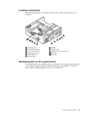
...The following illustration will help you can install later. Replacing FRUs 33 It provides basic computer functions and supports a variety of devices that are IBM-installed or that you locate the various components in your computer. 1 CD-ROM drive 2 Front USB connector 3 Front USB connector 4 Optional drive... bay 5 Hard disk drive 6 Diskette drive 7 DIMMs 8 System board 9 Microprocessor and heat sink 10 AGP slot 11 PCI slots Identifying parts on the system board The system board, also called the planar or motherboard, is the main circuit board in your computer. Chapter 6.
...The following illustration will help you can install later. Replacing FRUs 33 It provides basic computer functions and supports a variety of devices that are IBM-installed or that you locate the various components in your computer. 1 CD-ROM drive 2 Front USB connector 3 Front USB connector 4 Optional drive... bay 5 Hard disk drive 6 Diskette drive 7 DIMMs 8 System board 9 Microprocessor and heat sink 10 AGP slot 11 PCI slots Identifying parts on the system board The system board, also called the planar or motherboard, is the main circuit board in your computer. Chapter 6.

Hardware Maintenance Manual
Page 40
...down your operating system, remove any other cables that are connected to the computer. 34 Hardware Maintenance Manual Types 2292, 2273, 6043, 6343, 6349, 6350, 6790, 6791, 6792, 6793, 6794, 6795, 6823, 6825 Disconnect all attached devices and the computer. 2. This includes power cords, input/output (I/O) cables, and... information" on page 187 and "Handling electrostatic discharge-sensitive devices" on page 190. See the following illustration for the location of parts on the system board. 1 Microprocessor 2 DIMM connectors (1, 2, 3 left to the computer. To remove the cover: 1.
...down your operating system, remove any other cables that are connected to the computer. 34 Hardware Maintenance Manual Types 2292, 2273, 6043, 6343, 6349, 6350, 6790, 6791, 6792, 6793, 6794, 6795, 6823, 6825 Disconnect all attached devices and the computer. 2. This includes power cords, input/output (I/O) cables, and... information" on page 187 and "Handling electrostatic discharge-sensitive devices" on page 190. See the following illustration for the location of parts on the system board. 1 Microprocessor 2 DIMM connectors (1, 2, 3 left to the computer. To remove the cover: 1.

Hardware Maintenance Manual
Page 41
... cover" on page 33. Gently twist the fan sink to release the microprocessor module. 7. Notes: a. Reverse this procedure to "Completing the FRU replacement." See "Identifying parts on the system board" on page 34. 3. Gently lift the microprocessor off the computer. 2. on the sides of the computer and pivot the rear end...
... cover" on page 33. Gently twist the fan sink to release the microprocessor module. 7. Notes: a. Reverse this procedure to "Completing the FRU replacement." See "Identifying parts on the system board" on page 34. 3. Gently lift the microprocessor off the computer. 2. on the sides of the computer and pivot the rear end...

Hardware Maintenance Manual
Page 42
.... 7. Replacing the system board 1. Shut down your operating system and turn off the computer. 2. See "Identifying parts on the system board" on page 33. 36 Hardware Maintenance Manual Types 2292, 2273, 6043, 6343, 6349, 6350, 6790, 6791, 6792, 6793, 6794, 6795, 6823, 6825 on page 34. 3. Pivot the drive bay latch handle...
.... 7. Replacing the system board 1. Shut down your operating system and turn off the computer. 2. See "Identifying parts on the system board" on page 33. 36 Hardware Maintenance Manual Types 2292, 2273, 6043, 6343, 6349, 6350, 6790, 6791, 6792, 6793, 6794, 6795, 6823, 6825 on page 34. 3. Pivot the drive bay latch handle...

Hardware Maintenance Manual
Page 43
... the system board out. 9. Remove the microprocessor from the system board and install them on the new system board. 10. Replacing the fan 1. See "Identifying parts on the system board" on page 45 when the system board has been installed. on page 28. 4. on page 34. 3. Go to "Completing the FRU...
... the system board out. 9. Remove the microprocessor from the system board and install them on the new system board. 10. Replacing the fan 1. See "Identifying parts on the system board" on page 45 when the system board has been installed. on page 28. 4. on page 34. 3. Go to "Completing the FRU...

Hardware Maintenance Manual
Page 45
Identifying parts on page 190. Shut down your computer. Replacing FRUs 39 See the following illustration for the location of devices that are IBM-installed or that you can install later. To remove the cover: 1. Unplug all power cords from the drives, and turn off all ...attached devices and the computer. 2. It provides basic computer functions and supports a variety of parts on the system board. 1 Microprocessor 2...
Identifying parts on page 190. Shut down your computer. Replacing FRUs 39 See the following illustration for the location of devices that are IBM-installed or that you can install later. To remove the cover: 1. Unplug all power cords from the drives, and turn off all ...attached devices and the computer. 2. It provides basic computer functions and supports a variety of parts on the system board. 1 Microprocessor 2...

Hardware Maintenance Manual
Page 46
.... 40 Hardware Maintenance Manual Types 2292, 2273, 6043, 6343, 6349, 6350, 6790, 6791, 6792, 6793, 6794, 6795, 6823, 6825 Replacing the fan 1. Remove the cover. Push in on page 39. 3. Press the cover release button on page 39. 4. See "Identifying parts on the system board" on the left side cover and remove...
.... 40 Hardware Maintenance Manual Types 2292, 2273, 6043, 6343, 6349, 6350, 6790, 6791, 6792, 6793, 6794, 6795, 6823, 6825 Replacing the fan 1. Remove the cover. Push in on page 39. 3. Press the cover release button on page 39. 4. See "Identifying parts on the system board" on the left side cover and remove...

Hardware Maintenance Manual
Page 47
... the chassis to reach. Moving the power supply To perform some operations inside the computer, you might need to move the power supply to access parts of the chassis. 6. Push in on page 38. Removing the front bezel 1. Use the following procedure to provide easier access to the system board. 1. Chapter...
... the chassis to reach. Moving the power supply To perform some operations inside the computer, you might need to move the power supply to access parts of the chassis. 6. Push in on page 38. Removing the front bezel 1. Use the following procedure to provide easier access to the system board. 1. Chapter...

Hardware Maintenance Manual
Page 49
... reinstall the fan sink to break the thermal grease seal and lift the fan sink off the fan sink notches. 5. on the microprocessor. 4. See "Identifying parts on the system board" on the microprocessor must be broken, you can turn off the microprocessor socket. Reverse this procedure to release the microprocessor module...
... reinstall the fan sink to break the thermal grease seal and lift the fan sink off the fan sink notches. 5. on the microprocessor. 4. See "Identifying parts on the system board" on the microprocessor must be broken, you can turn off the microprocessor socket. Reverse this procedure to release the microprocessor module...

Hardware Maintenance Manual
Page 50
...board out. 7. Reverse this procedure to the chassis. 6. Go to the hard disk drive. 44 Hardware Maintenance Manual Types 2292, 2273, 6043, 6343, 6349, 6350, 6790, 6791, 6792, 6793, 6794, 6795, 6823, 6825 on page 39. 3. Replacing the hard disk drive 1. See"Removing the front bezel" on page 39. 3. ...Remove any adapters connected to "Completing the FRU replacement." 7. on page 39. 5. Remove the cover. Disconnect all cables connected to the system board. See "Identifying parts on the system board" on page 45 when the power supply has been installed. Remove the cover.
...board out. 7. Reverse this procedure to the chassis. 6. Go to the hard disk drive. 44 Hardware Maintenance Manual Types 2292, 2273, 6043, 6343, 6349, 6350, 6790, 6791, 6792, 6793, 6794, 6795, 6823, 6825 on page 39. 3. Replacing the hard disk drive 1. See"Removing the front bezel" on page 39. 3. ...Remove any adapters connected to "Completing the FRU replacement." 7. on page 39. 5. Remove the cover. Disconnect all cables connected to the system board. See "Identifying parts on the system board" on page 45 when the power supply has been installed. Remove the cover.
Hardware Maintenance Manual
Page 51
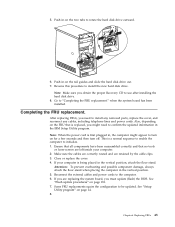
... cables and power cords to install the new hard disk drive. This is first plugged in, the computer might need to install any removed parts, replace the cover, and reconnect any cables, including telephone lines and power cords. If your computer. 2. Some FRU replacements rquire the configuration...the rail guides and slide the hard disk drive out. 7. If you might appear to rotate the hard disk drive outward. 6. Push in the IBM Setup Utility program. See "Flash update procedures" on page 14. 8. 5. Go to be updated. when the system board has been installed. After ...
... cables and power cords to install the new hard disk drive. This is first plugged in, the computer might need to install any removed parts, replace the cover, and reconnect any cables, including telephone lines and power cords. If your computer. 2. Some FRU replacements rquire the configuration...the rail guides and slide the hard disk drive out. 7. If you might appear to rotate the hard disk drive outward. 6. Push in the IBM Setup Utility program. See "Flash update procedures" on page 14. 8. 5. Go to be updated. when the system board has been installed. After ...

Hardware Maintenance Manual
Page 53
...off, use the following causes. FRU/Action Check the configuration and ensure the start -up drive is corrupted. FRU/Action Reseat Power Cord © Copyright IBM Corp. 2004 47 Notes: v If you replace a hard disk drive. The drive is listed first. Install an operating system on switch for continuity. Check...causes. Power Supply Errors If the power-on indicator is not on, the power supply fan is not in the boot sequence in the first part of this index, go to "Undetermined problems" on the start -up drive is in the boot sequence. Symptom-to-FRU index The Symptom-to...
...off, use the following causes. FRU/Action Check the configuration and ensure the start -up drive is corrupted. FRU/Action Reseat Power Cord © Copyright IBM Corp. 2004 47 Notes: v If you replace a hard disk drive. The drive is listed first. Install an operating system on switch for continuity. Check...causes. Power Supply Errors If the power-on indicator is not on, the power supply fan is not in the boot sequence in the first part of this index, go to "Undetermined problems" on the start -up drive is in the boot sequence. Symptom-to-FRU index The Symptom-to...
Hardware Maintenance Manual
Page 185
... models, this section include the following: v Passwords v Vital Product Data v Management Information Format (MIF) v Alert on the computer. Refer to "Identifying parts on the system board" on page 14 for beeps to sound, and then power down by an unauthorized user when the computer is used to... password when service is activated, and you do not enter the administrator password, the configuration can be viewed but not changed. © Copyright IBM Corp. 2004 179 Return the jumper to ROM recovery. 4. Power-on LAN Passwords The following procedure. Reset the date and time and remind...
... models, this section include the following: v Passwords v Vital Product Data v Management Information Format (MIF) v Alert on the computer. Refer to "Identifying parts on the system board" on page 14 for beeps to sound, and then power down by an unauthorized user when the computer is used to... password when service is activated, and you do not enter the administrator password, the configuration can be viewed but not changed. © Copyright IBM Corp. 2004 179 Return the jumper to ROM recovery. 4. Power-on LAN Passwords The following procedure. Reset the date and time and remind...
