User Guide
Page 34
Infoprint 1332/1352/1372 Tools required Flat-blade screwdrivers, various sizes Phillips screwdrivers, various sizes 7.0 mm nut driver 5.5 mm wrench Needlenose pliers Diagonal side cutters Spring hook Feeler gauges Analog or digital multimeter Parallel wrap plug 1319128 Twinax/serial debug cable 1381963 Flash light (optional) 1-14 Service Manual
Infoprint 1332/1352/1372 Tools required Flat-blade screwdrivers, various sizes Phillips screwdrivers, various sizes 7.0 mm nut driver 5.5 mm wrench Needlenose pliers Diagonal side cutters Spring hook Feeler gauges Analog or digital multimeter Parallel wrap plug 1319128 Twinax/serial debug cable 1381963 Flash light (optional) 1-14 Service Manual
User Guide
Page 38
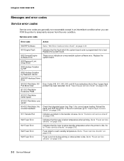
...Transfer Roll Indicates a problem in an intermittent condition when you can POR the printer to "Input tray(s) service check" on page 2-52. 2-2 Service Manual Replace the system board. 903 Paperport Link Driver Error 904 Interface Violation by RIP 905 Interface Violation by Paperport Device 906 RIP...Pick Motor over speed 914 DC Pick Motor: No encoder feedback Check the integrated paper tray (Tray 1) for correct paper loading. Infoprint 1332/1352/1372 Messages and error codes Service error codes Service error codes are indications that a Tray 1 paper feed Pick Motor Stall ...
...Transfer Roll Indicates a problem in an intermittent condition when you can POR the printer to "Input tray(s) service check" on page 2-52. 2-2 Service Manual Replace the system board. 903 Paperport Link Driver Error 904 Interface Violation by RIP 905 Interface Violation by Paperport Device 906 RIP...Pick Motor over speed 914 DC Pick Motor: No encoder feedback Check the integrated paper tray (Tray 1) for correct paper loading. Infoprint 1332/1352/1372 Messages and error codes Service error codes Service error codes are indications that a Tray 1 paper feed Pick Motor Stall ...
User Guide
Page 114
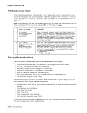
... weight settings for the media being used. • Test the printer using plain paper (20 lb). If incorrect, replace the system board. The voltage at J4-1 measures approximately +5 V dc. See "Printhead 1 (Infoprint 1332)" on page 7-10, "Printhead 2 (Infoprint 1352)" on page 7-11, or "Printhead 3 (1372)" on...cartridge if available before proceeding with the service checks. • Use Tray 1 to NORMAL. • Test the printer using plain paper (20 lb). An incorrect printer driver for print quality of the mirror motor cable connected to J5 and J4 on page 7-12. Note: A 201 paper...
... weight settings for the media being used. • Test the printer using plain paper (20 lb). If incorrect, replace the system board. The voltage at J4-1 measures approximately +5 V dc. See "Printhead 1 (Infoprint 1332)" on page 7-10, "Printhead 2 (Infoprint 1352)" on page 7-11, or "Printhead 3 (1372)" on...cartridge if available before proceeding with the service checks. • Use Tray 1 to NORMAL. • Test the printer using plain paper (20 lb). An incorrect printer driver for print quality of the mirror motor cable connected to J5 and J4 on page 7-12. Note: A 201 paper...

User Guide
Page 160
... the reference screw clockwise with a 7 mm nut driver until you obtain the results you check the diamonds on page 3-16. When replacing the alignment assembly, it touches the back of the Quick Test Page before making any adjustments to be removed from the printer. Infoprint 1332/1352/1372 Paper alignment assembly adjustment Do the...
... the reference screw clockwise with a 7 mm nut driver until you obtain the results you check the diamonds on page 3-16. When replacing the alignment assembly, it touches the back of the Quick Test Page before making any adjustments to be removed from the printer. Infoprint 1332/1352/1372 Paper alignment assembly adjustment Do the...

