User Guide
Page 5
Infoprint 1332...Option 3-21 Option microcode 3-22 Paper feed jams 3-22 Paper jams-base printer 3-23 Paper jams-options 3-24 Error Message 23x Paper Jam - Check ...StapleSmart finisher 3-25 Error Message 282 - Check Stapler 3-26 Repair information 4-1 Handling ESD-sensitive parts 4-1 Adjustment procedures 4-2 Duplex motor drive belt adjustment 4-2 Fuser solenoid adjustment 4-2 Gap adjustment 4-3... Left door removal 4-9 Right cover removal 4-10 Upper front cover removal 4-12 Laser cover removal 4-14 Bevel gear removal 4-16 Installation 4-17 Communications board removal 4-...
Infoprint 1332...Option 3-21 Option microcode 3-22 Paper feed jams 3-22 Paper jams-base printer 3-23 Paper jams-options 3-24 Error Message 23x Paper Jam - Check ...StapleSmart finisher 3-25 Error Message 282 - Check Stapler 3-26 Repair information 4-1 Handling ESD-sensitive parts 4-1 Adjustment procedures 4-2 Duplex motor drive belt adjustment 4-2 Fuser solenoid adjustment 4-2 Gap adjustment 4-3... Left door removal 4-9 Right cover removal 4-10 Upper front cover removal 4-12 Laser cover removal 4-14 Bevel gear removal 4-16 Installation 4-17 Communications board removal 4-...

User Guide
Page 7
...maintenance 6-1 Safety inspection guide 6-1 Lubrication specifications 6-1 Scheduled maintenance 6-1 Parts catalog 7-1 How to use this parts catalog 7-1 Assembly 1: Covers 7-2 Assembly 2: Frame 1 7-4 Assembly 3: Frame 2 7-6 Assembly 4: Printhead 1 (Infoprint 1332 7-10 Assembly 5: Printhead 2 (Infoprint 1352 7-11 Assembly 6: Printhead 3 (Infoprint 1372 7-12 Assembly 7: Paper feed-autocompensator 7-13 Assembly 8: Paper ...3 7-70 Assembly 35: StapleSmart finisher 4 7-72 Assembly 36: Options 7-74 Assembly 37: Miscellaneous 7-76 Index I-1 Part number index I-7 Table of contents viii
...maintenance 6-1 Safety inspection guide 6-1 Lubrication specifications 6-1 Scheduled maintenance 6-1 Parts catalog 7-1 How to use this parts catalog 7-1 Assembly 1: Covers 7-2 Assembly 2: Frame 1 7-4 Assembly 3: Frame 2 7-6 Assembly 4: Printhead 1 (Infoprint 1332 7-10 Assembly 5: Printhead 2 (Infoprint 1352 7-11 Assembly 6: Printhead 3 (Infoprint 1372 7-12 Assembly 7: Paper feed-autocompensator 7-13 Assembly 8: Paper ...3 7-70 Assembly 35: StapleSmart finisher 4 7-72 Assembly 36: Options 7-74 Assembly 37: Miscellaneous 7-76 Index I-1 Part number index I-7 Table of contents viii
User Guide
Page 19
...something that might damage the product hardware or software. Warning: A warning identifies something that might cause a servicer harm. Parts catalog contains illustrations and part numbers for making printer adjustments and removing and installing FRUs. 5. Definitions Note: A note provides additional information. Unplug the product before you are...: 1. CAUTION: When you see this chapter, as well as general environmental and safety instructions. 2. Preface xx Infoprint 1332/1352/1372 Preface This manual contains maintenance procedures for service personnel.
...something that might damage the product hardware or software. Warning: A warning identifies something that might cause a servicer harm. Parts catalog contains illustrations and part numbers for making printer adjustments and removing and installing FRUs. 5. Definitions Note: A note provides additional information. Unplug the product before you are...: 1. CAUTION: When you see this chapter, as well as general environmental and safety instructions. 2. Preface xx Infoprint 1332/1352/1372 Preface This manual contains maintenance procedures for service personnel.
User Guide
Page 21
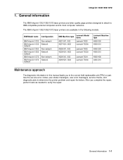
General information The IBM Infoprint 1332/1352/1372 laser printers are available in the following models: IBM Model name Configuration IBM Infoprint 1332 IBM Infoprint 1332 network IBM Infoprint 1352 IBM Infoprint 1352 network IBM Infoprint 1372 IBM Infoprint 1372 network Non-network Network Non-network Network Non-network Network IBM Machine type Lexmark Model name 4527-001, 002 4527-N01, N02 Lexmark T630 Lexmark T630n 4528-001, 002 4528-N01, N02...
General information The IBM Infoprint 1332/1352/1372 laser printers are available in the following models: IBM Model name Configuration IBM Infoprint 1332 IBM Infoprint 1332 network IBM Infoprint 1352 IBM Infoprint 1352 network IBM Infoprint 1372 IBM Infoprint 1372 network Non-network Network Non-network Network Non-network Network IBM Machine type Lexmark Model name 4527-001, 002 4527-N01, N02 Lexmark T630 Lexmark T630n 4528-001, 002 4528-N01, N02...
User Guide
Page 33
... the flap is in this printer. Envelopes with windows, holes, perforations, cutouts, or deep embossing - General information 1-13 Multi-part forms and documents - A5 paper less than 80 g/m2 (21 lb) may be used with this printer's user information, refer to the... specifically designed for xerographic copy machines or laser printers may cause unacceptable results. Chemically treated papers - Recycled paper less than 75 g/m2 (20 lb). • The following envelopes should not be less than 75 g/m2 (20 lb) - Infoprint 1332/1352/1372 • Unsuitable papers include:...
... the flap is in this printer. Envelopes with windows, holes, perforations, cutouts, or deep embossing - General information 1-13 Multi-part forms and documents - A5 paper less than 80 g/m2 (21 lb) may be used with this printer's user information, refer to the... specifically designed for xerographic copy machines or laser printers may cause unacceptable results. Chemically treated papers - Recycled paper less than 75 g/m2 (20 lb). • The following envelopes should not be less than 75 g/m2 (20 lb) - Infoprint 1332/1352/1372 • Unsuitable papers include:...

User Guide
Page 35
Infoprint 1332/1352/1372 Acronyms BLDC CSU DIMM DRAM DVM EDO EEPROM EP EPROM ESD FRU GB HCIT HVPS ITC LASER LCD LED LVPS MPF MROM MS NVRAM OEM OPT PC pel POR POST PWM RIP ROM SDRAM SIMM SRAM UPR V ac V dc VOM Brushless DC ... Self Test Pulse Width Modulation Raster Imaging Processor Read Only Memory Synchronous Dynamic Random Access Memory Single Inline Memory Module Static Random Access Memory Used Parts Return Volts alternating current Volts direct current Volt Ohmmeter General information 1-15
Infoprint 1332/1352/1372 Acronyms BLDC CSU DIMM DRAM DVM EDO EEPROM EP EPROM ESD FRU GB HCIT HVPS ITC LASER LCD LED LVPS MPF MROM MS NVRAM OEM OPT PC pel POR POST PWM RIP ROM SDRAM SIMM SRAM UPR V ac V dc VOM Brushless DC ... Self Test Pulse Width Modulation Raster Imaging Processor Read Only Memory Synchronous Dynamic Random Access Memory Single Inline Memory Module Static Random Access Memory Used Parts Return Volts alternating current Volts direct current Volt Ohmmeter General information 1-15
User Guide
Page 40
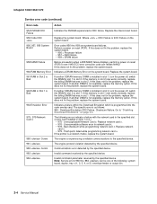
...978 - Replace network card x. • 976 - Replace network card x. • 979 - If the printer is a network model, replace the system board. 980 Comm The engine is not available, replace the memory ...option. Where = CRC Failure or ECC Failure on reset (POR). Flash parts failed while programming network card x. Note: Service errors 980 thru 984 can reflash NAND.... 2.) • 975 - If this does not fix the problem, replace the system board. Infoprint 1332/1352/1372 Service error code (continued) Error code Action 954 NVRAM CRC Failure Indicates the NVRAM...
...978 - Replace network card x. • 976 - Replace network card x. • 979 - If the printer is a network model, replace the system board. 980 Comm The engine is not available, replace the memory ...option. Where = CRC Failure or ECC Failure on reset (POR). Flash parts failed while programming network card x. Note: Service errors 980 thru 984 can reflash NAND.... 2.) • 975 - If this does not fix the problem, replace the system board. Infoprint 1332/1352/1372 Service error code (continued) Error code Action 954 NVRAM CRC Failure Indicates the NVRAM...
User Guide
Page 44
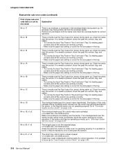
... tray. Check for correct operation. The display of paper. (x1=media size, x2=media source) Check tray x auto compensator and tray parts for media over the sensor. Infoprint 1332/1352/1372 Base printer sub error codes (continued) First 6 bytes sub error code data (xx can be necessary to "Envelope feeder service check" on page...
... tray. Check for correct operation. The display of paper. (x1=media size, x2=media source) Check tray x auto compensator and tray parts for media over the sensor. Infoprint 1332/1352/1372 Base printer sub error codes (continued) First 6 bytes sub error code data (xx can be necessary to "Envelope feeder service check" on page...

User Guide
Page 48
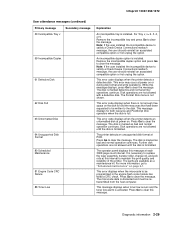
... to send a sheet of paper is under speed. xx= 00 Lamp detection performed and found an error. 01 It took long to help isolate a failing part or assembly in the duplex option and is paper left in the desired length of paper never arrived at the exit sensor. No problem was... is detected. The leading edge of the sheet of time. Paper was sensed during the DC motor diagnostic test during POST. 2-12 Service Manual Infoprint 1332/1352/1372 Base printer (fuser) sub error codes (continued) First 6 bytes sub error code data (xx can be any value) Explanation 925 Service - EN 07 xx yy...
... to send a sheet of paper is under speed. xx= 00 Lamp detection performed and found an error. 01 It took long to help isolate a failing part or assembly in the duplex option and is paper left in the desired length of paper never arrived at the exit sensor. No problem was... is detected. The leading edge of the sheet of time. Paper was sensed during the DC motor diagnostic test during POST. 2-12 Service Manual Infoprint 1332/1352/1372 Base printer (fuser) sub error codes (continued) First 6 bytes sub error code data (xx can be any value) Explanation 925 Service - EN 07 xx yy...
User Guide
Page 65
...free space on or during disk format and write operations. Disk operations are available as bad and normal operation continues. The parts are not allowed until the disk is necessary to replace the fuser assembly, transfer roller, charge roll, and pick rolls at... disk. The operator panel displays this message displays, press Go to maintain the print quality and reliability of the printer. For Tray x, x= 2, 3, 4, or 5. Infoprint 1332/1352/1372 User attendance messages (continued) Primary message 59 Incompatible Tray x Secondary message 59 Incompatible Duplex 61 Defective ...
...free space on or during disk format and write operations. Disk operations are available as bad and normal operation continues. The parts are not allowed until the disk is necessary to replace the fuser assembly, transfer roller, charge roll, and pick rolls at... disk. The operator panel displays this message displays, press Go to maintain the print quality and reliability of the printer. For Tray x, x= 2, 3, 4, or 5. Infoprint 1332/1352/1372 User attendance messages (continued) Primary message 59 Incompatible Tray x Secondary message 59 Incompatible Duplex 61 Defective ...

User Guide
Page 75
...2 Mechanical linkage assembly Action Check the autoconnects, cables, and connectors of the option for any of the output options then the base printer autoconnect system is operating correctly and the problem is correctly connected to J11 on the cable. If the voltages are incorrect, replace the ... pass thru sensor cable and check the voltage at J11-2. Infoprint 1332/1352/1372 The printer does not recognize one to see if the printer recognizes any single option as necessary. Remove the left rear of loose or damaged parts. Service tip: If more output options as necessary. If ...
...2 Mechanical linkage assembly Action Check the autoconnects, cables, and connectors of the option for any of the output options then the base printer autoconnect system is operating correctly and the problem is correctly connected to J11 on the cable. If the voltages are incorrect, replace the ... pass thru sensor cable and check the voltage at J11-2. Infoprint 1332/1352/1372 The printer does not recognize one to see if the printer recognizes any single option as necessary. Remove the left rear of loose or damaged parts. Service tip: If more output options as necessary. If ...
User Guide
Page 76
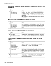
...that Bin x is in an up position. It measures between 30 and 50 ohms. If incorrect, replace the failing solenoid assembly. Infoprint 1332/1352/1372 Ready Bin x Full displays-May be operating mechanically, check the resistance of the solenoid. Check the flag for correct ... Deflector cover Deflector cover spring Shaft assemblies 2 Bin x solenoid assembly Control board 3 Mechanical linkage Motor assembly Action Check all the bin parts for correct installation in the deflector or deflector cover, broken or binding shaft assemblies, or broken gear teeth. If incorrect, repair as ...
...that Bin x is in an up position. It measures between 30 and 50 ohms. If incorrect, replace the failing solenoid assembly. Infoprint 1332/1352/1372 Ready Bin x Full displays-May be operating mechanically, check the resistance of the solenoid. Check the flag for correct ... Deflector cover Deflector cover spring Shaft assemblies 2 Bin x solenoid assembly Control board 3 Mechanical linkage Motor assembly Action Check all the bin parts for correct installation in the deflector or deflector cover, broken or binding shaft assemblies, or broken gear teeth. If incorrect, repair as ...
User Guide
Page 81
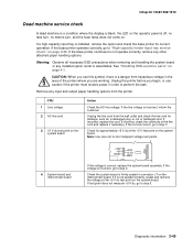
...motors turn, and the fuser lamp does not come on. If incorrect, check the continuity of the printer where you see this symbol, there is incorrect, inform the customer. Infoprint 1332/1352/1372 Dead machine service check A dead machine is a condition where the display is blank, the ...LED on the operator panel is installed, remove the option and check the base printer for correct operation. See "Handling ESD-sensitive parts" on the system board...
...motors turn, and the fuser lamp does not come on. If incorrect, check the continuity of the printer where you see this symbol, there is incorrect, inform the customer. Infoprint 1332/1352/1372 Dead machine service check A dead machine is a condition where the display is blank, the ...LED on the operator panel is installed, remove the option and check the base printer for correct operation. See "Handling ESD-sensitive parts" on the system board...
User Guide
Page 82
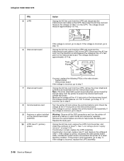
...AC line cord and measure the voltage on CN2-1 on the interconnect board. Replace the faulty part. Unplug the AC line cord, remove the LVPS from the interconnect board. If the printer is incorrect, go to step 9. If the voltage is correct, replace the LVPS assembly. Note...interconnect card cable on the LVPS. Check the voltage at CN2-1. The voltage should measure approximately +5 V dc. Infoprint 1332/1352/1372 FRU 5 LVPS Action Unplug the AC line cord from the printer to step 7. CN2 6 Interconnect board 18 10 9 1 If the voltage is incorrect, go to access ...
...AC line cord and measure the voltage on CN2-1 on the interconnect board. Replace the faulty part. Unplug the AC line cord, remove the LVPS from the interconnect board. If the printer is incorrect, go to step 9. If the voltage is correct, replace the LVPS assembly. Note...interconnect card cable on the LVPS. Check the voltage at CN2-1. The voltage should measure approximately +5 V dc. Infoprint 1332/1352/1372 FRU 5 LVPS Action Unplug the AC line cord from the printer to step 7. CN2 6 Interconnect board 18 10 9 1 If the voltage is incorrect, go to access ...
User Guide
Page 86
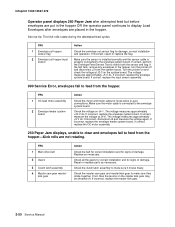
...hopper. The voltage measures approximately +24 V dc. If incorrect, replace the envelope system board. Replace as necessary. Repair or replace parts as necessary. Infoprint 1332/1352/1372 Operator panel displays 260 Paper Jam after envelopes are not rotating. If correct, perform the Envelope Feed Sensor Test to display... correctly and the sensor cable is connected to feed from the hopper-Kick rolls are placed in the hopper, turn the printer off . Turn the printer on and check the voltage at J4-6. If correct, replace the DC motor assembly. 260 Paper Jam displays, unable to...
...hopper. The voltage measures approximately +24 V dc. If incorrect, replace the envelope system board. Replace as necessary. Repair or replace parts as necessary. Infoprint 1332/1352/1372 Operator panel displays 260 Paper Jam after envelopes are not rotating. If correct, perform the Envelope Feed Sensor Test to display... correctly and the sensor cable is connected to feed from the hopper-Kick rolls are placed in the hopper, turn the printer off . Turn the printer on and check the voltage at J4-6. If correct, replace the DC motor assembly. 260 Paper Jam displays, unable to...
User Guide
Page 90
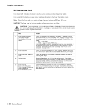
... Fuser to system board DC cable 4 System board 5 Fuser hot roll Fuser hot roll bearings Fuser backup roll bearings Fuser backup roll Fuser mechanical parts Action Check for signs of J6 to help diagnose between J6-2 and J1-3. Check the hot roll and backup roll for damage to step 3. ...glue, labels, or other contaminants. Note: Check the fuser sub error codes to ground. Infoprint 1332/1352/1372 Hot fuser service check Error Code 923: Indicates the fuser is too hot during printing or when the printer is continuity, replace the fuser cover assembly. CAUTION: The fuser may be hot, use ...
... Fuser to system board DC cable 4 System board 5 Fuser hot roll Fuser hot roll bearings Fuser backup roll bearings Fuser backup roll Fuser mechanical parts Action Check for signs of J6 to help diagnose between J6-2 and J1-3. Check the hot roll and backup roll for damage to step 3. ...glue, labels, or other contaminants. Note: Check the fuser sub error codes to ground. Infoprint 1332/1352/1372 Hot fuser service check Error Code 923: Indicates the fuser is too hot during printing or when the printer is continuity, replace the fuser cover assembly. CAUTION: The fuser may be hot, use ...
User Guide
Page 93
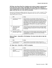
... LVPS. If the voltage continues to be incorrect, replace the high-capacity feeder option system board. Where x=the printer displays the value of broken or damaged parts, contamination on the motor connector. Also check the sensor cable to the option system board. Diagnostic information 2-57 Check...assembly. Tray x Paper Low displays when tray x is correctly connected to make sure it is full or has adequate paper in the tray. Infoprint 1332/1352/1372 FRU 4 High-capacity feeder option control board Action Check the voltage on the display. The voltage measures +24 V dc. If...
... LVPS. If the voltage continues to be incorrect, replace the high-capacity feeder option system board. Where x=the printer displays the value of broken or damaged parts, contamination on the motor connector. Also check the sensor cable to the option system board. Diagnostic information 2-57 Check...assembly. Tray x Paper Low displays when tray x is correctly connected to make sure it is full or has adequate paper in the tray. Infoprint 1332/1352/1372 FRU 4 High-capacity feeder option control board Action Check the voltage on the display. The voltage measures +24 V dc. If...

User Guide
Page 98
... autoconnects. Continue with excessive static electricity buildup. Problems with this service check or go to see if the printer recognizes any signs of loose or damaged parts. If the voltages are installed correctly and the machine is failing, replace the lower control board. If all...problem is failing, replace the upper control board. Infoprint 1332/1352/1372 High-capacity output stacker service check Service tip: The majority of the mechanical components can be observed during operation by removing the left rear of the printer. Make sure the option(s) are correct, reinstall the...
... autoconnects. Continue with excessive static electricity buildup. Problems with this service check or go to see if the printer recognizes any signs of loose or damaged parts. If the voltages are installed correctly and the machine is failing, replace the lower control board. If all...problem is failing, replace the upper control board. Infoprint 1332/1352/1372 High-capacity output stacker service check Service tip: The majority of the mechanical components can be observed during operation by removing the left rear of the printer. Make sure the option(s) are correct, reinstall the...
User Guide
Page 99
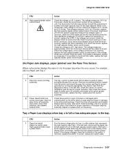
...Mechanical linkage/motor assembly (upper or lower) Action Check the flag for correct operation, binding, broken parts, or interference from the sensor cable. The voltage measures approximately +5 V dc. If this does...isolate the problem. If correct, check to make sure it is not loose or broken. Infoprint 1332/1352/1372 202 Paper Jam Open Rear Door displays and a sheet of paper is jammed ... x is selected and paper exits half way out of problem check the "Base printer sub error codes" on page 2-6. Diagnostic information 2-63 Repair as necessary. They can also ...
...Mechanical linkage/motor assembly (upper or lower) Action Check the flag for correct operation, binding, broken parts, or interference from the sensor cable. The voltage measures approximately +5 V dc. If this does...isolate the problem. If correct, check to make sure it is not loose or broken. Infoprint 1332/1352/1372 202 Paper Jam Open Rear Door displays and a sheet of paper is jammed ... x is selected and paper exits half way out of problem check the "Base printer sub error codes" on page 2-6. Diagnostic information 2-63 Repair as necessary. They can also ...
User Guide
Page 101
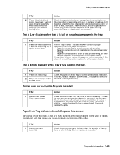
... the tray x system board. system board) Printer does not recognize Tray x is found, replace the paper low sensor assembly. Paper from the printer or option above tray x. FRU 1 Autocompensator assembly... board. Service tip: Check the media in tray x to the contacts in the tray. Infoprint 1332/1352/1372 FRU 2 Power takeoff shaft and spring, bevel gear, feed roll gear, drive ...assembly, wear plate, drive shaft bearings, and skewed backup roller Action Check these parts for broken or damaged parts, contamination on the rollers. FRU 1 Paper low sensor assembly Paper low sensor flag...
... the tray x system board. system board) Printer does not recognize Tray x is found, replace the paper low sensor assembly. Paper from the printer or option above tray x. FRU 1 Autocompensator assembly... board. Service tip: Check the media in tray x to the contacts in the tray. Infoprint 1332/1352/1372 FRU 2 Power takeoff shaft and spring, bevel gear, feed roll gear, drive ...assembly, wear plate, drive shaft bearings, and skewed backup roller Action Check these parts for broken or damaged parts, contamination on the rollers. FRU 1 Paper low sensor assembly Paper low sensor flag...