
User Guide
Page 1
... inches 2 Preparation 6 Switch Housing PAG E 12 13 PAG E PAG E PAG E Tools Needed Mounting Options Ceiling Bracket 3 Ladder Downrod PAG E PAG E 4 Wiring 5 Canopy PAG E PAG E 7 Light Kit 14 PAG E 10 11 Maintenance & Cleaning Troubleshooting ?? PAG E 16 ? 17 PAG E PAG E 1 M0038-01 • 10/22/12 • © Hunter Fan Company We are proud of Contents www.HunterFan.com 1.888.830.1326 PAG E Congratulations on purchasing your new Hunter® ceiling fan! Table of our work...
... inches 2 Preparation 6 Switch Housing PAG E 12 13 PAG E PAG E PAG E Tools Needed Mounting Options Ceiling Bracket 3 Ladder Downrod PAG E PAG E 4 Wiring 5 Canopy PAG E PAG E 7 Light Kit 14 PAG E 10 11 Maintenance & Cleaning Troubleshooting ?? PAG E 16 ? 17 PAG E PAG E 1 M0038-01 • 10/22/12 • © Hunter Fan Company We are proud of Contents www.HunterFan.com 1.888.830.1326 PAG E Congratulations on purchasing your new Hunter® ceiling fan! Table of our work...
User Guide
Page 2
... service panel. c.2 - WARNINGS w.1 - w.2 - Use only Hunter replacement parts. To avoid possible electrical shock, before installing or servicing your wiring 30 inches from blade tip to nearest wall or obstruction 7 feet from building structure and/or an outlet box marked acceptable for fan support of blade to the floor Assess location You may need a friend to help you cannot lock the circuit breakers in the off the circuit breakers to see fan weight Ceiling...
... service panel. c.2 - WARNINGS w.1 - w.2 - Use only Hunter replacement parts. To avoid possible electrical shock, before installing or servicing your wiring 30 inches from blade tip to nearest wall or obstruction 7 feet from building structure and/or an outlet box marked acceptable for fan support of blade to the floor Assess location You may need a friend to help you cannot lock the circuit breakers in the off the circuit breakers to see fan weight Ceiling...
User Guide
Page 3
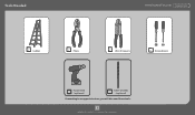
Tools Needed www.HunterFan.com 1.888.830.1326 Ladder Pliers Wire Strippers Screwdrivers Power Drill (optional) 9/64" Drill Bit (optional) If mounting to a support structure, you will also need these tools. 3 M0038-01 • 10/22/12 • © Hunter Fan Company
Tools Needed www.HunterFan.com 1.888.830.1326 Ladder Pliers Wire Strippers Screwdrivers Power Drill (optional) 9/64" Drill Bit (optional) If mounting to a support structure, you will also need these tools. 3 M0038-01 • 10/22/12 • © Hunter Fan Company
User Guide
Page 4
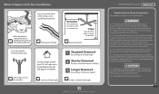
... Downrod & an Angled Mounting Kit Standard Mounting Style Ceiling Outlet Box (required) Use Standard Mounting or Low-Profile Mounting to determine if your fan by a standard downrod (included). 34O CEILING Mounting Options www.HunterFan.com 1.88686.823608.139236 OPTION1 OPTION 2 WALL If you have an angled ceiling: 1. SITUATI SITUATI 4 M0038-01 • 10/22/12 • © Hunter Fan Company Support Structure Angled Mounting Style Ceiling Outlet Box (required) Use Angled Mounting to hang the fan from a flat ceiling. Angled Mounting Use...
... Downrod & an Angled Mounting Kit Standard Mounting Style Ceiling Outlet Box (required) Use Standard Mounting or Low-Profile Mounting to determine if your fan by a standard downrod (included). 34O CEILING Mounting Options www.HunterFan.com 1.88686.823608.139236 OPTION1 OPTION 2 WALL If you have an angled ceiling: 1. SITUATI SITUATI 4 M0038-01 • 10/22/12 • © Hunter Fan Company Support Structure Angled Mounting Style Ceiling Outlet Box (required) Use Angled Mounting to hang the fan from a flat ceiling. Angled Mounting Use...

User Guide
Page 5
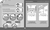
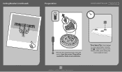
..." pilot holes outlet box. To avoid possible electrical shock, before installing your fan, disconnect the power by turning off the circuit breakers to the outlet box associated with box) when securing to support structure with the wall switch location. Ceiling Bracket www.HunterFan.com 1.888.830.1326 For angled ceilings, point opening toward peak. Use wood screws Use machine screws (included) when securing (provided with outlet to approved electrical outlet existing ceiling fan-rated box...
..." pilot holes outlet box. To avoid possible electrical shock, before installing your fan, disconnect the power by turning off the circuit breakers to the outlet box associated with box) when securing to support structure with the wall switch location. Ceiling Bracket www.HunterFan.com 1.888.830.1326 For angled ceilings, point opening toward peak. Use wood screws Use machine screws (included) when securing (provided with outlet to approved electrical outlet existing ceiling fan-rated box...
User Guide
Page 6
Save the screws. Time Saver Tip: Get a helper to insert grommets, found in the hardware bag, into the blades while you're doing the next couple of steps. 6 M0038-01 • 10/22/12 • © Hunter Fan Company They will be needed for blade iron installation. Remove the shipping blocks from the motor. Ceiling Bracket (continued) Preparation KEEP DISCA www.HunterFan.com 1.888.830.1326 RD !
Save the screws. Time Saver Tip: Get a helper to insert grommets, found in the hardware bag, into the blades while you're doing the next couple of steps. 6 M0038-01 • 10/22/12 • © Hunter Fan Company They will be needed for blade iron installation. Remove the shipping blocks from the motor. Ceiling Bracket (continued) Preparation KEEP DISCA www.HunterFan.com 1.888.830.1326 RD !

User Guide
Page 7
Option 1 Downrod Standard Downrod for ceilings 8-10' high www.HunterFan.com 1.888.830.1326 skip to next page If you need a different downrod length follow these steps: Longer Downrod for angled ceilings or 1 ceilings 10' or higher Steps 1-5 to remove standard downrod pipe 2 3 4 5 Included (pre-assembled) Option 3 Option 2 Shorter Downrod for fans installed close to ceiling Included Sold Separately Slide Slide 10 9 8 7 6 Steps 6-10 to reassemble with new pipe 7 M0038-01 • 10/22/12 • © Hunter Fan Company
Option 1 Downrod Standard Downrod for ceilings 8-10' high www.HunterFan.com 1.888.830.1326 skip to next page If you need a different downrod length follow these steps: Longer Downrod for angled ceilings or 1 ceilings 10' or higher Steps 1-5 to remove standard downrod pipe 2 3 4 5 Included (pre-assembled) Option 3 Option 2 Shorter Downrod for fans installed close to ceiling Included Sold Separately Slide Slide 10 9 8 7 6 Steps 6-10 to reassemble with new pipe 7 M0038-01 • 10/22/12 • © Hunter Fan Company

User Guide
Page 8
DO NOT HAND TIGHTEN. Hand tighten the downrod (at least 4-5 full turns) until it stops. 8" The wires can be cut, but leave at least 8" extending from the top of the downrod. 3/8" 8 M0038-01 • 10/22/12 • © Hunter Fan Company Tighten the setscrew with pliers. If the setscrew is not tightened securely, the fan may fall. Remove the pre-installed setscrew so that the downrod can be inserted. Downrod (continued) www.HunterFan.com 1.888.830.1326 (not to scale) CUT & STRIP KEEP! KEEP 3/8" 8" !
DO NOT HAND TIGHTEN. Hand tighten the downrod (at least 4-5 full turns) until it stops. 8" The wires can be cut, but leave at least 8" extending from the top of the downrod. 3/8" 8 M0038-01 • 10/22/12 • © Hunter Fan Company Tighten the setscrew with pliers. If the setscrew is not tightened securely, the fan may fall. Remove the pre-installed setscrew so that the downrod can be inserted. Downrod (continued) www.HunterFan.com 1.888.830.1326 (not to scale) CUT & STRIP KEEP! KEEP 3/8" 8" !

User Guide
Page 9
Let the canopy sit loosely on top of the fan. Place the downrod ball into the slot in the ceiling bracket. 9 M0038-01 • 10/22/12 • © Hunter Fan Company DO NOT PICK THE FAN UP BY THE CANOPY OR WIRES. Downrod (continued) www.HunterFan.com 1.888.830.1326 Put the wires and downrod through the canopy.
Let the canopy sit loosely on top of the fan. Place the downrod ball into the slot in the ceiling bracket. 9 M0038-01 • 10/22/12 • © Hunter Fan Company DO NOT PICK THE FAN UP BY THE CANOPY OR WIRES. Downrod (continued) www.HunterFan.com 1.888.830.1326 Put the wires and downrod through the canopy.
User Guide
Page 10
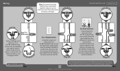
... orange wire connector from the hardware bag, connect the 3 grounding wires (green, green/ yellow stripe, or bare copper) coming from the fan. Connect the second (ungrounded) wire from the ceiling to CAUTION c.1 on the other side of the outlet box. 10 M0038-01 • 10/22/12 • © Hunter Fan Company FR OM CEILING BRAC Refer to the blue wire from the ceiling, downrod, and hanging bracket. Black...
... orange wire connector from the hardware bag, connect the 3 grounding wires (green, green/ yellow stripe, or bare copper) coming from the fan. Connect the second (ungrounded) wire from the ceiling to CAUTION c.1 on the other side of the outlet box. 10 M0038-01 • 10/22/12 • © Hunter Fan Company FR OM CEILING BRAC Refer to the blue wire from the ceiling, downrod, and hanging bracket. Black...
User Guide
Page 11
Canopy Screw Holes www.HunterFan.com 1.888.830.1326 Position the canopy so that, when lifted into place, the canopy fits into place so that the screw holes are aligned. Insert the two canopy screws found in the hardware bag. 11 M0038-01 • 10/22/12 • © Hunter Fan Company Note: Fan style may vary. Lift the canopy into the hanging bracket as shown.
Canopy Screw Holes www.HunterFan.com 1.888.830.1326 Position the canopy so that, when lifted into place, the canopy fits into place so that the screw holes are aligned. Insert the two canopy screws found in the hardware bag. 11 M0038-01 • 10/22/12 • © Hunter Fan Company Note: Fan style may vary. Lift the canopy into the hanging bracket as shown.
User Guide
Page 12
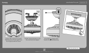
For cleaning the fan, use soft brushes or cloths to the motor with the blade iron armature screws, then securely tighten after removing the shipping blocks (page 6)? You need them for this step. Cleaning agents may damage the finishes. Blades Remember the screws that you kept after both screws are attached. 12 M0038-01 • 10/22/12 • © Hunter Fan Company Your blades are shielded with screws found in...
For cleaning the fan, use soft brushes or cloths to the motor with the blade iron armature screws, then securely tighten after removing the shipping blocks (page 6)? You need them for this step. Cleaning agents may damage the finishes. Blades Remember the screws that you kept after both screws are attached. 12 M0038-01 • 10/22/12 • © Hunter Fan Company Your blades are shielded with screws found in...

User Guide
Page 13
... to properly secure all three (3) screws. Feed the wire plug through the center hole of the upper switch housing, then wrap keyhole slots around the screws and twist counterclockwise. 13 M0038-01 • 10/22/12 • © Hunter Fan Company Insert the third screw, found in the switch housing fixture falling. Switch Housing www.HunterFan.com 1.888.830.1326 Screw two (2) housing assembly screws from the hardware bag halfway into...
... to properly secure all three (3) screws. Feed the wire plug through the center hole of the upper switch housing, then wrap keyhole slots around the screws and twist counterclockwise. 13 M0038-01 • 10/22/12 • © Hunter Fan Company Insert the third screw, found in the switch housing fixture falling. Switch Housing www.HunterFan.com 1.888.830.1326 Screw two (2) housing assembly screws from the hardware bag halfway into...
User Guide
Page 14
... do I install my fan without the light kit?" 14 M0038-01 • 10/22/12 • © Hunter Fan Company Make sure the lower switch housing is securely attached to install your fan without a light kit? Light Kit www.HunterFan.com 1.888.830.1326 Connect the plugs from the upper and lower switch housings. Install the three switch housing screws found in the light fixture falling. Want to the upper switch housing. Screw Holes Lift the lower switch housing up the colored markings on the connectors.
... do I install my fan without the light kit?" 14 M0038-01 • 10/22/12 • © Hunter Fan Company Make sure the lower switch housing is securely attached to install your fan without a light kit? Light Kit www.HunterFan.com 1.888.830.1326 Connect the plugs from the upper and lower switch housings. Install the three switch housing screws found in the light fixture falling. Want to the upper switch housing. Screw Holes Lift the lower switch housing up the colored markings on the connectors.

User Guide
Page 15
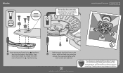
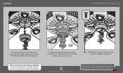
... for fan operation instructions. Finally, thread only the light pull chain through the hole in the finial and screw the finial onto the threaded rod. Note: In compliance with US federal energy regulations, this ceiling fan contains a device that restricts its light output. Light Kit (continued) www.HunterFan.com 1.888.830.1326 Metal Plate Light Pull Chain Fan Pull Chain Globe Globe Keeper Finial Cap Finial YCOOUNG'RRAETUDLAOTIONNES!! Exceeding the wattage 15 limit marked on and off . The light pull chain controls the light fixture: on...
... for fan operation instructions. Finally, thread only the light pull chain through the hole in the finial and screw the finial onto the threaded rod. Note: In compliance with US federal energy regulations, this ceiling fan contains a device that restricts its light output. Light Kit (continued) www.HunterFan.com 1.888.830.1326 Metal Plate Light Pull Chain Fan Pull Chain Globe Globe Keeper Finial Cap Finial YCOOUNG'RRAETUDLAOTIONNES!! Exceeding the wattage 15 limit marked on and off . The light pull chain controls the light fixture: on...

User Guide
Page 16
... ON Turn Power Metal Plate Globe Globe Keeper Finial Cap Finial Reverse Switch Changing the bulbs - move the reverse switch to prevent scratching. Cleaning the fan - Unscrew bulbs and replace with your other hand. For questions regarding removing a light kit, call 16 customer service 1-888-830-1326. unscrew the finial and remove it from the threaded rod. Reinstall the globe assembly. use soft brushes or cloths to the opposite position. Changing the direction of same type and wattage. Carefully remove the globe. M0038-01...
... ON Turn Power Metal Plate Globe Globe Keeper Finial Cap Finial Reverse Switch Changing the bulbs - move the reverse switch to prevent scratching. Cleaning the fan - Unscrew bulbs and replace with your other hand. For questions regarding removing a light kit, call 16 customer service 1-888-830-1326. unscrew the finial and remove it from the threaded rod. Reinstall the globe assembly. use soft brushes or cloths to the opposite position. Changing the direction of same type and wattage. Carefully remove the globe. M0038-01...
User Guide
Page 17
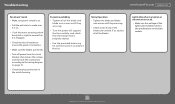
... to the wiring diagram on page 10. • Check the plug connection in the switch housing. Troubleshooting www.HunterFan.com 1.888.830.1326 Fan doesn't work • Make sure power switch is on. • Pull the pull chain to make sure it is on. • Push the motor reversing switch firmly left or right to ensure that the hanger ball is turned on. • Make sure the blades spin freely...
... to the wiring diagram on page 10. • Check the plug connection in the switch housing. Troubleshooting www.HunterFan.com 1.888.830.1326 Fan doesn't work • Make sure power switch is on. • Pull the pull chain to make sure it is on. • Push the motor reversing switch firmly left or right to ensure that the hanger ball is turned on. • Make sure the blades spin freely...


