Owner's Manual
Page 1
installation and operation manual for Hunter Ceiling Fans TYPE 3 Models 42700-01 • 01/15/08 For Your Records and Warranty Assistance Model Name Catalog/Model No Serial No Date Purchased Where Purchased For reference also attach your receipt or a copy of your receipt to the manual.
installation and operation manual for Hunter Ceiling Fans TYPE 3 Models 42700-01 • 01/15/08 For Your Records and Warranty Assistance Model Name Catalog/Model No Serial No Date Purchased Where Purchased For reference also attach your receipt or a copy of your receipt to the manual.
Owner's Manual
Page 2
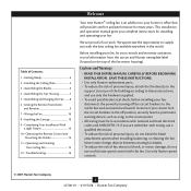
...; READ THIS ENTIRE MANUAL CAREFULLY BEFORE BEGINNING INSTALLATION. SAVE THESE INSTRUCTIONS. • Use only Hunter replacement parts. • To reduce the risk of personal injury, attach the fan directly to the support structure of the building according to these instructions, and use a solid... with national and local electrical codes and ANSI/NFPA 70. Use only Hunter speed controls. © 2007 Hunter Fan Company 2 42700-01 • 01/15/08 • Hunter Fan Company Never insert foreign objects between rotating fan blades. • To reduce the risk of fire, electrical shock, ...
...; READ THIS ENTIRE MANUAL CAREFULLY BEFORE BEGINNING INSTALLATION. SAVE THESE INSTRUCTIONS. • Use only Hunter replacement parts. • To reduce the risk of personal injury, attach the fan directly to the support structure of the building according to these instructions, and use a solid... with national and local electrical codes and ANSI/NFPA 70. Use only Hunter speed controls. © 2007 Hunter Fan Company 2 42700-01 • 01/15/08 • Hunter Fan Company Never insert foreign objects between rotating fan blades. • To reduce the risk of fire, electrical shock, ...
Owner's Manual
Page 3
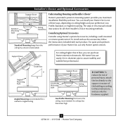
...including a wall-mounted or remote speed control. diameter pipe to these instructions, and use only Hunter speed controls. You can purchase Hunter extension downrods. All Hunter fans use the accessories, follow the instructions included with each product. Installer's Choice and Optional Accessories ... ceilings higher than 8 feet high CAUTION: To reduce the risk of personal injury, attach the fan directly to the support structure of your Hunter fan in this manual include instructions for ceilings less than 8 feet, you maximum installation flexibility and ease.
...including a wall-mounted or remote speed control. diameter pipe to these instructions, and use only Hunter speed controls. You can purchase Hunter extension downrods. All Hunter fans use the accessories, follow the instructions included with each product. Installer's Choice and Optional Accessories ... ceilings higher than 8 feet high CAUTION: To reduce the risk of personal injury, attach the fan directly to the support structure of your Hunter fan in this manual include instructions for ceilings less than 8 feet, you maximum installation flexibility and ease.
Owner's Manual
Page 4
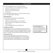
...-01 • 01/15/08 • Hunter Fan Company 1 • Getting Ready To install a ceiling fan, be sure you can direct you to a licensed installer or electrician. Gathering the Tools You will need help installing the fan, your Hunter fan dealer can do the following tools for installing ...the fan: • Electric drill with 9/64 in ceiling. • Drill holes for safety, reliable operation, ...
...-01 • 01/15/08 • Hunter Fan Company 1 • Getting Ready To install a ceiling fan, be sure you can direct you to a licensed installer or electrician. Gathering the Tools You will need help installing the fan, your Hunter fan dealer can do the following tools for installing ...the fan: • Electric drill with 9/64 in ceiling. • Drill holes for safety, reliable operation, ...
Owner's Manual
Page 5
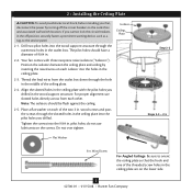
...the pilot holes you drilled in the ceiling plate are on the lower side. 5 42700-01 • 01/15/08 • Hunter Fan Company do not use slotted holes directly across from the outlet box down through the outermost holes in the off the circuit breakers to ...the ceiling plate with three neoprene noise isolators ("Isolators"). 2 • Installing the Ceiling Plate CAUTION: To avoid possible electrical shock, before installing your fan, disconnect the power by inserting the raised areas on each isolator into the holes in . Wood Screw For Angled Ceilings: Be sure to the ...
...the pilot holes you drilled in the ceiling plate are on the lower side. 5 42700-01 • 01/15/08 • Hunter Fan Company do not use slotted holes directly across from the outlet box down through the outermost holes in the off the circuit breakers to ...the ceiling plate with three neoprene noise isolators ("Isolators"). 2 • Installing the Ceiling Plate CAUTION: To avoid possible electrical shock, before installing your fan, disconnect the power by inserting the raised areas on each isolator into the holes in . Wood Screw For Angled Ceilings: Be sure to the ...
Owner's Manual
Page 6
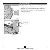
Attach the blade to the motor using the blade assembly screws. 3-4. 3 • Assembling tbe Blades Fan Motor Holes 3 • Assembling the Blades 3-1. Slide flat washers onto the shafts of the blade assembly screws. 3-3. Step 3-1 Blade Assembly Screw Step 3-2 Flat Washer 6 42700-01 • 01/15/08 • Hunter Fan Company Insert blade into slot. Repeat for each blade. Align the holes on the blade with the holes in the fan motor. 3-2.
Attach the blade to the motor using the blade assembly screws. 3-4. 3 • Assembling tbe Blades Fan Motor Holes 3 • Assembling the Blades 3-1. Slide flat washers onto the shafts of the blade assembly screws. 3-3. Step 3-1 Blade Assembly Screw Step 3-2 Flat Washer 6 42700-01 • 01/15/08 • Hunter Fan Company Insert blade into slot. Repeat for each blade. Align the holes on the blade with the holes in the fan motor. 3-2.
Owner's Manual
Page 7
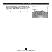
Steps 4-1 - 4-2 Assembly Screw Top Housing Hanger Adapter 7 42700-01 • 01/15/08 • Hunter Fan Company 4 • Assembling the Top Housing 4-1. Install three (3) assembly screws and tighten them securely. Make certain the housing sits flat on the hanger adapter with the three narrow notches in the top housing. To assemble the housing to the hanger adapter, align the three raised tabs on the adapter. 4-2.
Steps 4-1 - 4-2 Assembly Screw Top Housing Hanger Adapter 7 42700-01 • 01/15/08 • Hunter Fan Company 4 • Assembling the Top Housing 4-1. Install three (3) assembly screws and tighten them securely. Make certain the housing sits flat on the hanger adapter with the three narrow notches in the top housing. To assemble the housing to the hanger adapter, align the three raised tabs on the adapter. 4-2.
Owner's Manual
Page 8
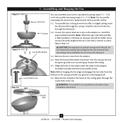
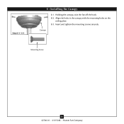
...the coating prevents the downrod from the fan through the downrod. 5-2. Raise the fan and place the hook on the adapter...Assembling and Hanging the Fan Steps 5-1 - 5-2 Downrod Canopy Steps 5-4 - 5-5 Low Profile Washer Low Profile Screw Step 5-6 You can assemble your fan for standard mounting (steps... will still be visible; Note: Before hanging the fan, align and engage the two tabs from a flat...low profile mounting, the downrod is normal. To assemble fan to hang down ) into the canopy. this coating... the threads. WARNING: Fan may fall if not assembled as directed in the hanger...
...the coating prevents the downrod from the fan through the downrod. 5-2. Raise the fan and place the hook on the adapter...Assembling and Hanging the Fan Steps 5-1 - 5-2 Downrod Canopy Steps 5-4 - 5-5 Low Profile Washer Low Profile Screw Step 5-6 You can assemble your fan for standard mounting (steps... will still be visible; Note: Before hanging the fan, align and engage the two tabs from a flat...low profile mounting, the downrod is normal. To assemble fan to hang down ) into the canopy. this coating... the threads. WARNING: Fan may fall if not assembled as directed in the hanger...
Owner's Manual
Page 9
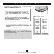
...the following two conditions: 1. The jumpers for the transmitter are located on 9 42700-01 • 01/15/08 • Hunter Fan Company CAUTION: The remote control device complies with this equipment. Setting Transmitter and Receiver Codes When two or more...of the receiver. Make sure that may not cause harmful interference. 2. Install the included 12-volt battery into the transmitter. WARNING: Use only the Hunter Fan speed control supplied with part 15 of the jumpers in the battery compartment. Receiver Jumpers Example Jumpers Settings Receiver 1 432 1 432 1 Receiver 2...
...the following two conditions: 1. The jumpers for the transmitter are located on 9 42700-01 • 01/15/08 • Hunter Fan Company CAUTION: The remote control device complies with this equipment. Setting Transmitter and Receiver Codes When two or more...of the receiver. Make sure that may not cause harmful interference. 2. Install the included 12-volt battery into the transmitter. WARNING: Use only the Hunter Fan speed control supplied with part 15 of the jumpers in the battery compartment. Receiver Jumpers Example Jumpers Settings Receiver 1 432 1 432 1 Receiver 2...
Owner's Manual
Page 10
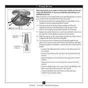
...the receiver lead wires to each side and feed the wires from the fan to the white wire (LIGHT OUT) from the receiver. 10 42700-01 • 01/15/08 • Hunter Fan Company Using the small wire connectors, connect the fan to the receiver as follows: • Connect the yellow wire from ...the fan to the yellow wire from the receiver. • Connect the pink wire from the...
...the receiver lead wires to each side and feed the wires from the fan to the white wire (LIGHT OUT) from the receiver. 10 42700-01 • 01/15/08 • Hunter Fan Company Using the small wire connectors, connect the fan to the receiver as follows: • Connect the yellow wire from ...the fan to the yellow wire from the receiver. • Connect the pink wire from the...
Owner's Manual
Page 11
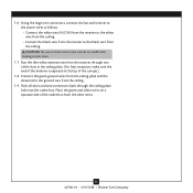
Run the thin white antenna wire from the other wires. 11 42700-01 • 01/15/08 • Hunter Fan Company CAUTION: Be sure no bare wire or wire strands are visible after making connections. 7-7. Connect the green ground wires from the ceiling plate and ... the black wire from the ceiling. 7-9. Place the green and white wires on a separate side of the canopy.) 7-8. Using the large wire connectors, connect the fan and receiver to the power wires as follows: • Connect the white wire (A/C IN) from the receiver to the white wire from the ceiling. •...
Run the thin white antenna wire from the other wires. 11 42700-01 • 01/15/08 • Hunter Fan Company CAUTION: Be sure no bare wire or wire strands are visible after making connections. 7-7. Connect the green ground wires from the ceiling plate and ... the black wire from the ceiling. 7-9. Place the green and white wires on a separate side of the canopy.) 7-8. Using the large wire connectors, connect the fan and receiver to the power wires as follows: • Connect the white wire (A/C IN) from the receiver to the white wire from the ceiling. •...
Owner's Manual
Page 12
Insert and tighten the mounting screws securely. Canopy Mounting Screw 12 42700-01 • 01/15/08 • Hunter Fan Company Steps 8-1- 8-3 8 • Installing the Canopy 8-1. Align the holes in the canopy with the mounting holes on the ceiling plate. 8-3. Holding the canopy, raise the fan off the hook. 8-2.
Insert and tighten the mounting screws securely. Canopy Mounting Screw 12 42700-01 • 01/15/08 • Hunter Fan Company Steps 8-1- 8-3 8 • Installing the Canopy 8-1. Align the holes in the canopy with the mounting holes on the ceiling plate. 8-3. Holding the canopy, raise the fan off the hook. 8-2.
Owner's Manual
Page 13
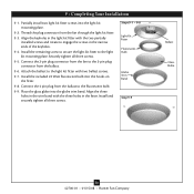
... light kit fitter with two ballast screws. 9-7. Place the glass globe into the hooks on the fitter. 9-8. Thread the plug connector from the fan to the fluorescent bulb. 9-9. Install the included 22 Watt fluorescent bulb into the globe trim band. Align the three holes in the trim band ...the ballast. 9-6. Steps 9-1 - 9-8 Light Kit Fitter Fluorescent Bulb Globe Trim Band Step 9-9 Ballast Glass Globe 13 42700-01 • 01/15/08 • Hunter Fan Company Partially install two light kit fitter screws into the light kit mounting plate. 9-2. Connect the 2-pin plug connector from the...
... light kit fitter with two ballast screws. 9-7. Place the glass globe into the hooks on the fitter. 9-8. Thread the plug connector from the fan to the fluorescent bulb. 9-9. Install the included 22 Watt fluorescent bulb into the globe trim band. Align the three holes in the trim band ...the ballast. 9-6. Steps 9-1 - 9-8 Light Kit Fitter Fluorescent Bulb Globe Trim Band Step 9-9 Ballast Glass Globe 13 42700-01 • 01/15/08 • Hunter Fan Company Partially install two light kit fitter screws into the light kit mounting plate. 9-2. Connect the 2-pin plug connector from the...
Owner's Manual
Page 14
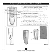
...12-volt type 23A, MN-21 battery for use with the screws already in the switch plate. Please contact your desired speed. Fan Speed Medium Fan Off Fan Light 10-3. The remote transmitter has individual buttons for proper battery disposal information. Step 10-6 14 42700-01 • 01/15.../08 • Hunter Fan Company Step 10-7 For best operation, start the fan by pressing high, then select your local battery recycling center for turning the fan off the light. 10-6. Or, you can mount the remote holder to turn...
...12-volt type 23A, MN-21 battery for use with the screws already in the switch plate. Please contact your desired speed. Fan Speed Medium Fan Off Fan Light 10-3. The remote transmitter has individual buttons for proper battery disposal information. Step 10-6 14 42700-01 • 01/15.../08 • Hunter Fan Company Step 10-7 For best operation, start the fan by pressing high, then select your local battery recycling center for turning the fan off the light. 10-6. Or, you can mount the remote holder to turn...
Owner's Manual
Page 15
...dampened cloth. In warm weather, use downward air flow pattern In cold weather, use an artistic agent, but never abrasive cleaning agents as the fan finish. If the remote control will damage the finish. 11-5. A vacuum cleaner brush nozzle can remove heavier dust. Clean wood finish blades ...the wall switch OFF. 11-3. 11 • Operating and Cleaning Your Ceiling Fan 11-1. Press the remote control's HIGH speed button. You may use upward air flow pattern 15 42700-01 • 01/15/08 • Hunter Fan Company Occasionally, apply a light coat of furniture polish for 5 days or...
...dampened cloth. In warm weather, use downward air flow pattern In cold weather, use an artistic agent, but never abrasive cleaning agents as the fan finish. If the remote control will damage the finish. 11-5. A vacuum cleaner brush nozzle can remove heavier dust. Clean wood finish blades ...the wall switch OFF. 11-3. 11 • Operating and Cleaning Your Ceiling Fan 11-1. Press the remote control's HIGH speed button. You may use upward air flow pattern 15 42700-01 • 01/15/08 • Hunter Fan Company Occasionally, apply a light coat of furniture polish for 5 days or...
Owner's Manual
Page 16
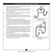
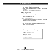
...the blade is cracked. If so, replace all connections according to the wiring the fan section. 3. Be sure that the hanger ball is secure. Turn power off, support fan very carefully, and check that the glass is properly seated. If you need parts ... canopy, check all the blades. 3. Check to balance the fan. 2. Tighten all blade and/or blade iron screws. 3. 12 • Troubleshooting Problem: Nothing happens; Problem: Excessive wobbling. 1. fan does not move. 1. Problem: Noisy operation. 1. Hunter Fan Company 2500 Frisco Avenue Memphis, Tennessee 38114 16 42700-01 &#...
...the blade is cracked. If so, replace all connections according to the wiring the fan section. 3. Be sure that the hanger ball is secure. Turn power off, support fan very carefully, and check that the glass is properly seated. If you need parts ... canopy, check all the blades. 3. Check to balance the fan. 2. Tighten all blade and/or blade iron screws. 3. 12 • Troubleshooting Problem: Nothing happens; Problem: Excessive wobbling. 1. fan does not move. 1. Problem: Noisy operation. 1. Hunter Fan Company 2500 Frisco Avenue Memphis, Tennessee 38114 16 42700-01 &#...


