
Installation Guide
Page 1
... octagonal 4" x 1-1/2" outlet box • Two #8 x 1-1/2" wood screws and washers • Approved connector for electrical wire Checklist for your fan manual and continue with 2 • Installing the Ceiling Plate. If you want to use the hole to your ceiling fan, go to install the support brace and outlet box. o Fan support system will hold full weight of the ceiling. Cut a 4" diameter hole through the inner holes of 1/16" into the ceiling. Steps 2 - 3 Step 3 Install a Support Brace, If Necessary...
... octagonal 4" x 1-1/2" outlet box • Two #8 x 1-1/2" wood screws and washers • Approved connector for electrical wire Checklist for your fan manual and continue with 2 • Installing the Ceiling Plate. If you want to use the hole to your ceiling fan, go to install the support brace and outlet box. o Fan support system will hold full weight of the ceiling. Cut a 4" diameter hole through the inner holes of 1/16" into the ceiling. Steps 2 - 3 Step 3 Install a Support Brace, If Necessary...

Owner's Manual
Page 1
Model Name Model No. Date Purchased Where Purchased Type 2 Models Owner's Guide and Installation Manual English Español Form# 45039-01 20101217 ©2010 Hunter Fan Co. For Your Records and Warranty Assistance For reference, also attach your receipt or a copy of your receipt to the manual.
Model Name Model No. Date Purchased Where Purchased Type 2 Models Owner's Guide and Installation Manual English Español Form# 45039-01 20101217 ©2010 Hunter Fan Co. For Your Records and Warranty Assistance For reference, also attach your receipt or a copy of your receipt to the manual.
Owner's Manual
Page 2
...; Wiring the Fan 9 5 • Installing the Canopy and Canopy Trim Ring 10 6 • Assembling the Blades 11 7 • Completing Your Installation With or Without a Bowl Light Fixture 12 8 • Operating and Cleaning Your Ceiling Fan 16 9 • Troubleshooting 17 Welcome Your new Hunter® ceiling fan is an addition to your records and warranty assistance, record information from the carton and Hunter nameplate label (located on the top of the fan motor housing). SAVE THESE INSTRUCTIONS. • Use only Hunter replacement parts...
...; Wiring the Fan 9 5 • Installing the Canopy and Canopy Trim Ring 10 6 • Assembling the Blades 11 7 • Completing Your Installation With or Without a Bowl Light Fixture 12 8 • Operating and Cleaning Your Ceiling Fan 16 9 • Troubleshooting 17 Welcome Your new Hunter® ceiling fan is an addition to your records and warranty assistance, record information from the carton and Hunter nameplate label (located on the top of the fan motor housing). SAVE THESE INSTRUCTIONS. • Use only Hunter replacement parts...
Owner's Manual
Page 3
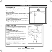
..., prepare a new fan site as walls or posts, within 30 inches of the fan blade tips. • e fan is directly below the joist or support brace. Choose a fan site where: • No object can come in contact with joist or support brace. • e bottom of the outlet box is secured to Section 2 • Installing the Ceiling Plate. Ceiling Hole • e outlet box clearance hole is suitable...
..., prepare a new fan site as walls or posts, within 30 inches of the fan blade tips. • e fan is directly below the joist or support brace. Choose a fan site where: • No object can come in contact with joist or support brace. • e bottom of the outlet box is secured to Section 2 • Installing the Ceiling Plate. Ceiling Hole • e outlet box clearance hole is suitable...
Owner's Manual
Page 4
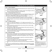
... electrician. 4 45039-01 • 12/17/10 • Hunter Fan Company If the joist is a ceiling joist directly above the ceiling hole. Attach the outlet box directly to your ceiling fan site. For instructions to install your ceiling fan, go to the support brace or joist with Section 2 • Installing the Ceiling Plate. Position it to the service panel. 5-2. read the fan supply line through the drywall or plaster of...
... electrician. 4 45039-01 • 12/17/10 • Hunter Fan Company If the joist is a ceiling joist directly above the ceiling hole. Attach the outlet box directly to your ceiling fan site. For instructions to install your ceiling fan, go to the support brace or joist with Section 2 • Installing the Ceiling Plate. Position it to the service panel. 5-2. read the fan supply line through the drywall or plaster of...
Owner's Manual
Page 5
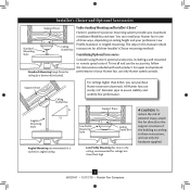
... ceiling Support Brace Low Profile Mounting Style Ceiling Outlet Box Low Profile Mounting fits close to these instructions, and use only Hunter speed controls. For quiet and optimum performance of three ways, depending on ceiling height and your Hunter fan, use only the hardware supplied. 5 45039-01 • 12/17/10 • Hunter Fan Company Installer's Choice and Optional Accessories Support Brace Standard Mounting Style Ceiling Outlet Box Standard Mounting hangs from the ceiling by a downrod (included). You can purchase Hunter extension downrods. Understanding Mounting...
... ceiling Support Brace Low Profile Mounting Style Ceiling Outlet Box Low Profile Mounting fits close to these instructions, and use only Hunter speed controls. For quiet and optimum performance of three ways, depending on ceiling height and your Hunter fan, use only the hardware supplied. 5 45039-01 • 12/17/10 • Hunter Fan Company Installer's Choice and Optional Accessories Support Brace Standard Mounting Style Ceiling Outlet Box Standard Mounting hangs from the ceiling by a downrod (included). You can purchase Hunter extension downrods. Understanding Mounting...
Owner's Manual
Page 6
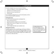
... ceiling. • Drill holes for any shipping damage to the included Parts Guide. If you are missing or damaged, contact your fan to avoid damage to a licensed installer or electrician. Check for and install wood screws. • Identify and connect electrical wires. • Lift 40 pounds. 1 • Getting Ready To install a ceiling fan, be sure you can direct you to the fan parts. Refer to the motor or fan blades. Installing Multiple Fans...
... ceiling. • Drill holes for any shipping damage to the included Parts Guide. If you are missing or damaged, contact your fan to avoid damage to a licensed installer or electrician. Check for and install wood screws. • Identify and connect electrical wires. • Lift 40 pounds. 1 • Getting Ready To install a ceiling fan, be sure you can direct you to the fan parts. Refer to the motor or fan blades. Installing Multiple Fans...
Owner's Manual
Page 7
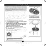
... four isolators are pointing toward the ceiling peak. Thread the supply wires from each of the ceiling plate. 2-5. Ceiling Plate 3" Wood Screw Steps 2-3 - 2-6 7 45039-01 • 12/17/10 • Hunter Fan Company The pilot holes should be 9/64" in place and were not removed during shipment. 2-3. Do not over tighten. 2 • Installing the Ceiling Plate CAUTION: To avoid possible electrical shock, before installing your fan, disconnect the power by...
... four isolators are pointing toward the ceiling peak. Thread the supply wires from each of the ceiling plate. 2-5. Ceiling Plate 3" Wood Screw Steps 2-3 - 2-6 7 45039-01 • 12/17/10 • Hunter Fan Company The pilot holes should be 9/64" in place and were not removed during shipment. 2-3. Do not over tighten. 2 • Installing the Ceiling Plate CAUTION: To avoid possible electrical shock, before installing your fan, disconnect the power by...
Owner's Manual
Page 8
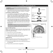
... remove the downrod. To assemble fan to make one piece.) Feed the wires from the fan through the canopy, adapter cover grommet, adapter cover, and canopy trim ring. (The adapter cover and adapter cover grommet may fall if not assembled as directed in the canopy with the hooks on the ceiling plate. 3-8. Note: When the pipe and ball assembly is normal. For Low Profile mounting: Note: For low profile mounting, the downrod is complete. The adapter cover and adapter cover grommet are not used for low profile mounting. 3-4. Align the holes in the washer...
... remove the downrod. To assemble fan to make one piece.) Feed the wires from the fan through the canopy, adapter cover grommet, adapter cover, and canopy trim ring. (The adapter cover and adapter cover grommet may fall if not assembled as directed in the canopy with the hooks on the ceiling plate. 3-8. Note: When the pipe and ball assembly is normal. For Low Profile mounting: Note: For low profile mounting, the downrod is complete. The adapter cover and adapter cover grommet are not used for low profile mounting. 3-4. Align the holes in the washer...
Owner's Manual
Page 9
... of the outlet box. 9 45039-01 • 12/17/10 • Hunter Fan Company Wire Connector Dual Switch Wiring Single Switch Wiring Connect the remaining wires as follows: Dual Switch Wiring: • The black wire (ungrounded) from the ceiling to the black wire (ungrounded) from the fan • The black/white wire (ungrounded) from the fan to the wire (ungrounded) for the wall switch Single Switch Wiring: • The black wire (ungrounded) from the ceiling to the white wire (grounded) from the fan. 4-5. Turn the...
... of the outlet box. 9 45039-01 • 12/17/10 • Hunter Fan Company Wire Connector Dual Switch Wiring Single Switch Wiring Connect the remaining wires as follows: Dual Switch Wiring: • The black wire (ungrounded) from the ceiling to the black wire (ungrounded) from the fan • The black/white wire (ungrounded) from the fan to the wire (ungrounded) for the wall switch Single Switch Wiring: • The black wire (ungrounded) from the ceiling to the white wire (grounded) from the fan. 4-5. Turn the...

Owner's Manual
Page 10
... canopy screw holes with the screw holes aligned, partially install two canopy screws into the hole between the two ceiling plate tabs.When all the holes are still in the hanger ball groove. Step 5-1 Tab Groove Step 5-2 Step 5-3 Canopy Canopy Trim Ring Canopy Screw 10 45039-01 • 12/17/10 • Hunter Fan Company Verify that must remain engaged while swinging the canopy for the following steps could cause the fan to remove the trim ring...
... canopy screw holes with the screw holes aligned, partially install two canopy screws into the hole between the two ceiling plate tabs.When all the holes are still in the hanger ball groove. Step 5-1 Tab Groove Step 5-2 Step 5-3 Canopy Canopy Trim Ring Canopy Screw 10 45039-01 • 12/17/10 • Hunter Fan Company Verify that must remain engaged while swinging the canopy for the following steps could cause the fan to remove the trim ring...

Owner's Manual
Page 11
... clean the blades. If your fan has grommets, insert them by hand into the holes on the blades. 6-2. Attach each blade, insert one blade mounting screw through the blade iron, and attach lightly to secure shipping blocks. 6-4. Remove the blade mounting screws and rubber shipping bumpers from the motor. Insert the second blade mounting screw, then securely tighten both mounting screws. Use a dry or slightly damp lint free cloth to a blade iron using three blade assembly screws. Your fan may appear slightly loose after screws are installed...
... clean the blades. If your fan has grommets, insert them by hand into the holes on the blades. 6-2. Attach each blade, insert one blade mounting screw through the blade iron, and attach lightly to secure shipping blocks. 6-4. Remove the blade mounting screws and rubber shipping bumpers from the motor. Insert the second blade mounting screw, then securely tighten both mounting screws. Use a dry or slightly damp lint free cloth to a blade iron using three blade assembly screws. Your fan may appear slightly loose after screws are installed...
Owner's Manual
Page 12
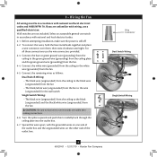
... Without a Bowl Light Fixture Your Hunter fan comes with this fan model. 7-1. The steps below direct you whether or not you are firmly situated in the housing with OR without the included light fixture. WARNING: Use only the light fixture supplied with an integrated light fixture assembly and an optional switch housing cap and plug button. Install the remaining screw into the switch housing mounting plate. 7-2. Steps 7-1 - 7-3 Housing Assembly Screw Upper Switch Housing 12 45039-01 • 12/17/10 • Hunter Fan Company CAUTION...
... Without a Bowl Light Fixture Your Hunter fan comes with this fan model. 7-1. The steps below direct you whether or not you are firmly situated in the housing with OR without the included light fixture. WARNING: Use only the light fixture supplied with an integrated light fixture assembly and an optional switch housing cap and plug button. Install the remaining screw into the switch housing mounting plate. 7-2. Steps 7-1 - 7-3 Housing Assembly Screw Upper Switch Housing 12 45039-01 • 12/17/10 • Hunter Fan Company CAUTION...
Owner's Manual
Page 13
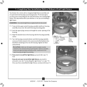
..., this ceiling fan contains a device that restricts its light output. Align the side screw holes in the upper and lower switch housings. Plug Connector Detail Plug Connector Housing Assembly Screw 13 45039-01 • 12/17/10 • Hunter Fan Company Steps 7-6 - 7-7 Lower Switch Housing Note: In compliance with three housing assembly screws. Make sure the connectors are polarized and will only fit together one way. 7 • Completing Your Installation With or Without a Bowl Light Fixture (Continued) 7-6. Attach the lower switch housing to...
..., this ceiling fan contains a device that restricts its light output. Align the side screw holes in the upper and lower switch housings. Plug Connector Detail Plug Connector Housing Assembly Screw 13 45039-01 • 12/17/10 • Hunter Fan Company Steps 7-6 - 7-7 Lower Switch Housing Note: In compliance with three housing assembly screws. Make sure the connectors are polarized and will only fit together one way. 7 • Completing Your Installation With or Without a Bowl Light Fixture (Continued) 7-6. Attach the lower switch housing to...
Owner's Manual
Page 14
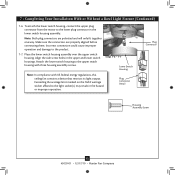
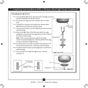
... grommet hole in the center of the cover plate. 7-10. Attach the extra pull chains (included) to the light and fan pull chains using the breakaway connector. (You may find the breakaway connector on the end of the cover plate. 7-11. Align the holes in the center of the glass bowl. Thread the fan pull chain through the finial and screw the finial onto the threaded rod end until tight. 7-13. First install B10 candelabra bulbs...
... grommet hole in the center of the cover plate. 7-10. Attach the extra pull chains (included) to the light and fan pull chains using the breakaway connector. (You may find the breakaway connector on the end of the cover plate. 7-11. Align the holes in the center of the glass bowl. Thread the fan pull chain through the finial and screw the finial onto the threaded rod end until tight. 7-13. First install B10 candelabra bulbs...
Owner's Manual
Page 15
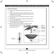
... light fixture, first disconnect the plug connectors between the two white wires. 7-16. Uninstall the connector and washer from the lower switch housing. 7-18. Install the switch housing cap and plug button to the lower switch housing. 7-21. 7 • Completing Your Installation With or Without a Bowl Light Fixture (Continued) Uninstalling the Light Fixture 7-14. Steps 7-16 - 7-18 Lower Switch Housing Male Dummy Terminal Female Dummy Terminal Cap Plug Button Step 7-20 15 45039-01 • 12/17/10 • Hunter Fan Company...
... light fixture, first disconnect the plug connectors between the two white wires. 7-16. Uninstall the connector and washer from the lower switch housing. 7-18. Install the switch housing cap and plug button to the lower switch housing. 7-21. 7 • Completing Your Installation With or Without a Bowl Light Fixture (Continued) Uninstalling the Light Fixture 7-14. Steps 7-16 - 7-18 Lower Switch Housing Male Dummy Terminal Female Dummy Terminal Cap Plug Button Step 7-20 15 45039-01 • 12/17/10 • Hunter Fan Company...
Owner's Manual
Page 16
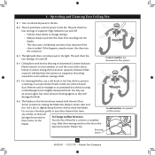
... the light. Reversing Switch In cold weather, use downward air flow pattern 8-5. Ceiling fans work best by blowing air downward (counterclockwise blade rotation) in sequence: High, Medium, Low and Off. • Pull the chain slowly to change settings. • Release slowly to the opposite position. You may use a furniture polish or any other cleaners that separates if the chain is jerked. 8 • Operating and Cleaning Your Ceiling Fan 8-1. The light pull chain controls power to prevent scratching. Remove surface...
... the light. Reversing Switch In cold weather, use downward air flow pattern 8-5. Ceiling fans work best by blowing air downward (counterclockwise blade rotation) in sequence: High, Medium, Low and Off. • Pull the chain slowly to change settings. • Release slowly to the opposite position. You may use a furniture polish or any other cleaners that separates if the chain is jerked. 8 • Operating and Cleaning Your Ceiling Fan 8-1. The light pull chain controls power to prevent scratching. Remove surface...
Owner's Manual
Page 17
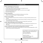
... resume power to the fan off at http://www.hunterfan.com. Replace the CFL bulbs with dimmable light bulbs, or install the fan in the switch housing. 4. Remove the shipping bumpers. Tighten the blade assembly screws and blade iron armature screws until snug. 2. Make sure the blades are securely attached to the blade irons, follow the instructions in the enclosed balancing kit to the blade assembly instructions provided. 2. Turn power off suddenly, but fan is cracked. Problem: CFL bulbs flicker when controlled by a dimming remote or wall control...
... resume power to the fan off at http://www.hunterfan.com. Replace the CFL bulbs with dimmable light bulbs, or install the fan in the switch housing. 4. Remove the shipping bumpers. Tighten the blade assembly screws and blade iron armature screws until snug. 2. Make sure the blades are securely attached to the blade irons, follow the instructions in the enclosed balancing kit to the blade assembly instructions provided. 2. Turn power off suddenly, but fan is cracked. Problem: CFL bulbs flicker when controlled by a dimming remote or wall control...
Parts Guide
Page 1
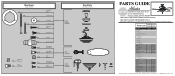
... Trim Ring Hanger Ball / Downrod Assembly Setscrew Low Profile Washer Canopy Screw Wood Screw 1.5" Wood Screw 3" Flat Washer Mounting Isolator * Screw, Low Profile Switch Housing Assembly Adapter Cover Light Kit Assembly Light bulb / Bulb Blade Iron Set Blade Set Screw, Blade Iron Armature Hardware Kit Blade Grommet Blade Assembly Screw Screw, Machine, 6-32 Wire Connector Screw, Switch Housing Assembly Globe/Shade Bottom Cap Finial Pull Chain Pendant Pull Chain Pull Chain Dummy Terminal, Male Dummy Terminal, Female Cap, Switch Housing Plug Button Balancing Kit Model # 21315 Asm. If parts...
... Trim Ring Hanger Ball / Downrod Assembly Setscrew Low Profile Washer Canopy Screw Wood Screw 1.5" Wood Screw 3" Flat Washer Mounting Isolator * Screw, Low Profile Switch Housing Assembly Adapter Cover Light Kit Assembly Light bulb / Bulb Blade Iron Set Blade Set Screw, Blade Iron Armature Hardware Kit Blade Grommet Blade Assembly Screw Screw, Machine, 6-32 Wire Connector Screw, Switch Housing Assembly Globe/Shade Bottom Cap Finial Pull Chain Pendant Pull Chain Pull Chain Dummy Terminal, Male Dummy Terminal, Female Cap, Switch Housing Plug Button Balancing Kit Model # 21315 Asm. If parts...


