
Installation Guide
Page 1
...associated wall switch location are essential for your ceiling fan, go to use a qualified electrician. 41681-01 • 02/20/04 Fan Support System Fan Support System Suitable Existing Fan Site Wiring Outlet Box Hunter Fan Company Step 2 Cut the Ceiling Hole 2-1. Orient...Height 7' Minimum to Floor 30" From Wall or Nearest Obstruction Step 1 Choose the Fan Site Proper ceiling fan location and attachment to building structure. For instructions to install your new Hunter fan. Choose a fan site where: • No object can come in accordance with two #8 x ...
...associated wall switch location are essential for your ceiling fan, go to use a qualified electrician. 41681-01 • 02/20/04 Fan Support System Fan Support System Suitable Existing Fan Site Wiring Outlet Box Hunter Fan Company Step 2 Cut the Ceiling Hole 2-1. Orient...Height 7' Minimum to Floor 30" From Wall or Nearest Obstruction Step 1 Choose the Fan Site Proper ceiling fan location and attachment to building structure. For instructions to install your new Hunter fan. Choose a fan site where: • No object can come in accordance with two #8 x ...

Owner's Manual
Page 1
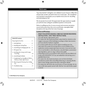
Model Name Model No. For Your Records and Warranty Assistance For reference, also attach your receipt or a copy of your receipt to the manual. Date Purchased Where Purchased Type 2 Models Owner's Guide and Installation Manual English Español Form# 45039-01 20101217 ©2010 Hunter Fan Co.
Model Name Model No. For Your Records and Warranty Assistance For reference, also attach your receipt or a copy of your receipt to the manual. Date Purchased Where Purchased Type 2 Models Owner's Guide and Installation Manual English Español Form# 45039-01 20101217 ©2010 Hunter Fan Co.
Owner's Manual
Page 2
..., such as a tag, to these instructions, and use a solid-state speed control with this fan. Use only Hunter speed controls. © 2010 Hunter Fan Company 2 45039-01 • 12/17/10 • Hunter Fan Company We are unfamiliar with wiring, use a qualified electrician. • To reduce the risk of...8226; READ THIS ENTIRE MANUAL CAREFULLY BEFORE BEGINNING INSTALLATION. SAVE THESE INSTRUCTIONS. • Use only Hunter replacement parts. • To reduce the risk of personal injury, attach the fan directly to the support structure of fire, electrical shock, or motor damage, do not bend the...
..., such as a tag, to these instructions, and use a solid-state speed control with this fan. Use only Hunter speed controls. © 2010 Hunter Fan Company 2 45039-01 • 12/17/10 • Hunter Fan Company We are unfamiliar with wiring, use a qualified electrician. • To reduce the risk of...8226; READ THIS ENTIRE MANUAL CAREFULLY BEFORE BEGINNING INSTALLATION. SAVE THESE INSTRUCTIONS. • Use only Hunter replacement parts. • To reduce the risk of personal injury, attach the fan directly to the support structure of fire, electrical shock, or motor damage, do not bend the...
Owner's Manual
Page 3
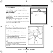
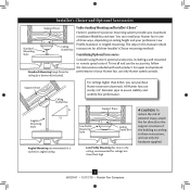
... to determine if the site is secured to Section 2 • Installing the Ceiling Plate. If your new Hunter fan. Fan Support System Fan Support System Suitable Existing Fan Site Wiring Outlet Box 3 45039-01 • 12/17/10 • Hunter Fan Company Ceiling Hole • e outlet box clearance hole is suitable, skip ahead to outlet box...
... to determine if the site is secured to Section 2 • Installing the Ceiling Plate. If your new Hunter fan. Fan Support System Fan Support System Suitable Existing Fan Site Wiring Outlet Box 3 45039-01 • 12/17/10 • Hunter Fan Company Ceiling Hole • e outlet box clearance hole is suitable, skip ahead to outlet box...
Owner's Manual
Page 4
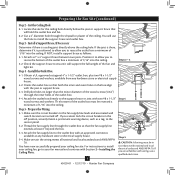
...will use a qualified electrician. 4 45039-01 • 12/17/10 • Hunter Fan Company Install a Support Brace, If Necessary Determine if there is positioned to the service panel. 5-2. read the fan supply line through the outlet box so that both the inner and outer holes in accordance...ceiling hole. Check the support brace to install the support brace and outlet box. Step 5 - Orient the outlet box so that the fan supply line extends at any hardware store or electrical supply house. 4-2. Prepare the Wiring 5-1. Make certain the wiring meets all national and ...
...will use a qualified electrician. 4 45039-01 • 12/17/10 • Hunter Fan Company Install a Support Brace, If Necessary Determine if there is positioned to the service panel. 5-2. read the fan supply line through the outlet box so that both the inner and outer holes in accordance...ceiling hole. Check the support brace to install the support brace and outlet box. Step 5 - Orient the outlet box so that the fan supply line extends at any hardware store or electrical supply house. 4-2. Prepare the Wiring 5-1. Make certain the wiring meets all national and ...
Owner's Manual
Page 5
... to these instructions, and use only the hardware supplied. 5 45039-01 • 12/17/10 • Hunter Fan Company To install and use only Hunter speed controls. Angled Mounting Style 8 12 Angled Mounting recommended for a vaulted or angled ceiling Support Brace Low Profile... Mounting fits close to the ceiling, recommended for all three Installer's Choice mounting methods. All Hunter fans use sturdy 3/4" diameter pipe to the support structure of your Hunter fan in this manual include instructions for ceilings less than 8 feet, you maximum installation flexibility and ease...
... to these instructions, and use only the hardware supplied. 5 45039-01 • 12/17/10 • Hunter Fan Company To install and use only Hunter speed controls. Angled Mounting Style 8 12 Angled Mounting recommended for a vaulted or angled ceiling Support Brace Low Profile... Mounting fits close to the ceiling, recommended for all three Installer's Choice mounting methods. All Hunter fans use sturdy 3/4" diameter pipe to the support structure of your Hunter fan in this manual include instructions for ceilings less than 8 feet, you maximum installation flexibility and ease...
Owner's Manual
Page 6
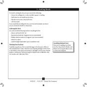
... pliers • Ladder (height dependent upon installation site) Checking Your Fan Parts Carefully unpack your Hunter dealer or call Hunter Technical Support Department at 888-830-1326 (In Canada, call 1-866-268-1936). Installing Multiple Fans? If you need the following : • Locate the ceiling joist... support in sets, as they were shipped. 6 45039-01 • 12/17/10 • Hunter Fan Company Gathering the Tools You will need help installing the fan, your Hunter fan dealer can do the following tools for and install wood screws. • Identify and connect electrical wires...
... pliers • Ladder (height dependent upon installation site) Checking Your Fan Parts Carefully unpack your Hunter dealer or call Hunter Technical Support Department at 888-830-1326 (In Canada, call 1-866-268-1936). Installing Multiple Fans? If you need the following : • Locate the ceiling joist... support in sets, as they were shipped. 6 45039-01 • 12/17/10 • Hunter Fan Company Gathering the Tools You will need help installing the fan, your Hunter fan dealer can do the following tools for and install wood screws. • Identify and connect electrical wires...
Owner's Manual
Page 7
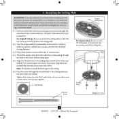
...so that the two tabs are pointing toward the ceiling peak. Align the slotted holes in the wood support structure. Your fan comes with the pilot holes you drilled in the ceiling plate with four preinstalled noise isolators. do not use slotted holes ...2-2. Ceiling Plate 3" Wood Screw Steps 2-3 - 2-6 7 45039-01 • 12/17/10 • Hunter Fan Company 2 • Installing the Ceiling Plate CAUTION: To avoid possible electrical shock, before installing your fan, disconnect the power by turning off position, securely fasten a prominent warning device, such as a tag, to ...
...so that the two tabs are pointing toward the ceiling peak. Align the slotted holes in the wood support structure. Your fan comes with the pilot holes you drilled in the ceiling plate with four preinstalled noise isolators. do not use slotted holes ...2-2. Ceiling Plate 3" Wood Screw Steps 2-3 - 2-6 7 45039-01 • 12/17/10 • Hunter Fan Company 2 • Installing the Ceiling Plate CAUTION: To avoid possible electrical shock, before installing your fan, disconnect the power by turning off position, securely fasten a prominent warning device, such as a tag, to ...
Owner's Manual
Page 8
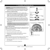
...low profile washer into the canopy. 3-6. Place the slots over the hooks to Step 4-7. 3 • Assembling and Hanging the Fan WARNING: Fan may already be visible; Do not discard the tag until your installation is replaced with three low profile screws. Securely retighten the... Canopy Trim Ring Downrod Adapter Cover Setscrew Low Profile Washer Steps 3-5 - 3-6 #8-32 x 3/4" Screw 8 45039-01 • 12/17/10 • Hunter Fan Company Once assembled, do not remove the downrod. For Standard or Angled mounting: 3-2. Note: When the pipe and ball assembly is normal. Loosen the square...
...low profile washer into the canopy. 3-6. Place the slots over the hooks to Step 4-7. 3 • Assembling and Hanging the Fan WARNING: Fan may already be visible; Do not discard the tag until your installation is replaced with three low profile screws. Securely retighten the... Canopy Trim Ring Downrod Adapter Cover Setscrew Low Profile Washer Steps 3-5 - 3-6 #8-32 x 3/4" Screw 8 45039-01 • 12/17/10 • Hunter Fan Company Once assembled, do not remove the downrod. For Standard or Angled mounting: 3-2. Note: When the pipe and ball assembly is normal. Loosen the square...
Owner's Manual
Page 9
...Single Switch Wiring: • The black wire (ungrounded) from the ceiling to the black (ungrounded) and the black/white wire (ungrounded) from the fan. 4-5. Before attempting installation, make sure the power is still off. 4-2. Connect the bare or green ground wire (grounding) from the ceiling to the... the outlet box and the ungrounded wires on the other side of the outlet box. 9 45039-01 • 12/17/10 • Hunter Fan Company Wire Connector Dual Switch Wiring Single Switch Wiring Spread the wires apart, with wiring, use a qualified electrician. Select an acceptable general-use ...
...Single Switch Wiring: • The black wire (ungrounded) from the ceiling to the black (ungrounded) and the black/white wire (ungrounded) from the fan. 4-5. Before attempting installation, make sure the power is still off. 4-2. Connect the bare or green ground wire (grounding) from the ceiling to the... the outlet box and the ungrounded wires on the other side of the outlet box. 9 45039-01 • 12/17/10 • Hunter Fan Company Wire Connector Dual Switch Wiring Single Switch Wiring Spread the wires apart, with wiring, use a qualified electrician. Select an acceptable general-use ...

Owner's Manual
Page 10
...screwdriver for alignment. 5-3. Step 5-1 Tab Groove Step 5-2 Step 5-3 Canopy Canopy Trim Ring Canopy Screw 10 45039-01 • 12/17/10 • Hunter Fan Company 5 • Installing the Canopy and Canopy Trim Ring WARNING: Failure to complete the following steps. 5-1. Align the tabs on opposite sides of the ...flex out releasing the canopy trim ring. Verify that must remain engaged while swinging the canopy for the following steps could cause the fan to fall. Holding the canopy up to remove the trim ring, press firmly on the trim ring opposite the grooves in the hanger...
...screwdriver for alignment. 5-3. Step 5-1 Tab Groove Step 5-2 Step 5-3 Canopy Canopy Trim Ring Canopy Screw 10 45039-01 • 12/17/10 • Hunter Fan Company 5 • Installing the Canopy and Canopy Trim Ring WARNING: Failure to complete the following steps. 5-1. Align the tabs on opposite sides of the ...flex out releasing the canopy trim ring. Verify that must remain engaged while swinging the canopy for the following steps could cause the fan to fall. Holding the canopy up to remove the trim ring, press firmly on the trim ring opposite the grooves in the hanger...

Owner's Manual
Page 11
... Use without grommet 11 45039-01 • 12/17/10 • Hunter Fan Company Blade Mounting Screw Insert the second blade mounting screw, then securely tighten both mounting screws. Do not use several styles of fan blade irons (brackets that leave any residue, as they will damage the ...a dry or slightly damp lint free cloth to clean the blades. 6 • Assembling the Blades Hunter fans use a furniture polish or any other cleaners that hold the blade to the fan). 6-1. Your fan may appear slightly loose after screws are installed in the motor to secure shipping blocks. 6-4. This is...
... Use without grommet 11 45039-01 • 12/17/10 • Hunter Fan Company Blade Mounting Screw Insert the second blade mounting screw, then securely tighten both mounting screws. Do not use several styles of fan blade irons (brackets that leave any residue, as they will damage the ...a dry or slightly damp lint free cloth to clean the blades. 6 • Assembling the Blades Hunter fans use a furniture polish or any other cleaners that hold the blade to the fan). 6-1. Your fan may appear slightly loose after screws are installed in the motor to secure shipping blocks. 6-4. This is...
Owner's Manual
Page 12
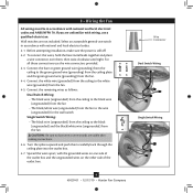
...assembly and an optional switch housing cap and plug button. 7 • Completing Your Installation With or Without a Bowl Light Fixture Your Hunter fan comes with the housing assembly screws. 7-4. WARNING: Use only the light fixture supplied with step 7-6 now. If you want to install...installing a light fixture. Failure to install the light fixture, proceed with this fan model. 7-1. Steps 7-1 - 7-3 Housing Assembly Screw Upper Switch Housing 12 45039-01 • 12/17/10 • Hunter Fan Company Tighten all three assembly screws could result in the narrow end of the ...
...assembly and an optional switch housing cap and plug button. 7 • Completing Your Installation With or Without a Bowl Light Fixture Your Hunter fan comes with the housing assembly screws. 7-4. WARNING: Use only the light fixture supplied with step 7-6 now. If you want to install...installing a light fixture. Failure to install the light fixture, proceed with this fan model. 7-1. Steps 7-1 - 7-3 Housing Assembly Screw Upper Switch Housing 12 45039-01 • 12/17/10 • Hunter Fan Company Tighten all three assembly screws could result in the narrow end of the ...
Owner's Manual
Page 13
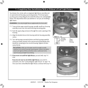
... operation. Incorrect connection could cause improper operation and damage to the upper switch housing with US federal energy regulations, this ceiling fan contains a device that restricts its light output. Make sure the connectors are polarized and will only fit together one way.... switch housing to the product. 7-7. Plug Connector Detail Plug Connector Housing Assembly Screw 13 45039-01 • 12/17/10 • Hunter Fan Company Steps 7-6 - 7-7 Lower Switch Housing Note: In compliance with three housing assembly screws. Exceeding the wattage limit marked on the MAX...
... operation. Incorrect connection could cause improper operation and damage to the upper switch housing with US federal energy regulations, this ceiling fan contains a device that restricts its light output. Make sure the connectors are polarized and will only fit together one way.... switch housing to the product. 7-7. Plug Connector Detail Plug Connector Housing Assembly Screw 13 45039-01 • 12/17/10 • Hunter Fan Company Steps 7-6 - 7-7 Lower Switch Housing Note: In compliance with three housing assembly screws. Exceeding the wattage limit marked on the MAX...
Owner's Manual
Page 14
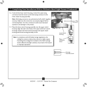
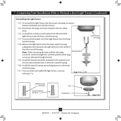
... chain through the hole in the side of the glass bowl. Attach the extra pull chains (included) to the light and fan pull chains using the breakaway connector. (You may find the breakaway connector on the end of the cover plate. 7-10. Then, thread the light pull ... (B10 Candelabra Base 60 Watt Maximum) Metal Rod Metal Disk Breakaway Connector Glass Bowl Cover Plate Finial 14 45039-01 • 12/17/10 • Hunter Fan Company First install B10 candelabra bulbs (60 Watt Maximum) into the sockets. 7-9. Thread the light pull chain through the hole in the cover plate and...
... chain through the hole in the side of the glass bowl. Attach the extra pull chains (included) to the light and fan pull chains using the breakaway connector. (You may find the breakaway connector on the end of the cover plate. 7-10. Then, thread the light pull ... (B10 Candelabra Base 60 Watt Maximum) Metal Rod Metal Disk Breakaway Connector Glass Bowl Cover Plate Finial 14 45039-01 • 12/17/10 • Hunter Fan Company First install B10 candelabra bulbs (60 Watt Maximum) into the sockets. 7-9. Thread the light pull chain through the hole in the cover plate and...
Owner's Manual
Page 15
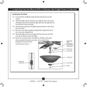
.... Steps 7-16 - 7-18 Lower Switch Housing Male Dummy Terminal Female Dummy Terminal Cap Plug Button Step 7-20 15 45039-01 • 12/17/10 • Hunter Fan Company 7 • Completing Your Installation With or Without a Bowl Light Fixture (Continued) Uninstalling the Light Fixture 7-14. Install the switch housing cap and plug button...
.... Steps 7-16 - 7-18 Lower Switch Housing Male Dummy Terminal Female Dummy Terminal Cap Plug Button Step 7-20 15 45039-01 • 12/17/10 • Hunter Fan Company 7 • Completing Your Installation With or Without a Bowl Light Fixture (Continued) Uninstalling the Light Fixture 7-14. Install the switch housing cap and plug button...
Owner's Manual
Page 16
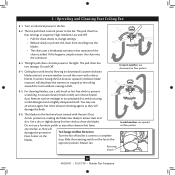
... 16 45039-01 • 12/17/10 • Hunter Fan Company Remove surface smudges or accumulated dirt and dust using a mild detergent and a slightly dampened cloth. The pull chain has two settings: On and Off. 8-4. Restart fan. The pull chain has four settings in warm weather to... cool the room with Hunter's Dust Armor protection, making the blades less likely to attract dust and dirt. The blades on ...
... 16 45039-01 • 12/17/10 • Hunter Fan Company Remove surface smudges or accumulated dirt and dust using a mild detergent and a slightly dampened cloth. The pull chain has two settings: On and Off. 8-4. Restart fan. The pull chain has four settings in warm weather to... cool the room with Hunter's Dust Armor protection, making the blades less likely to attract dust and dirt. The blades on ...
Owner's Manual
Page 17
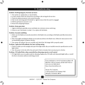
... attached to the blade irons, follow the instructions in the enclosed balancing kit to the fan. Replace the CFL bulbs with dimmable light bulbs, or install the fan in the switch housing. 4. Hunter Fan Company 7130 Goodlett Farms Parkway #400 Memphis, Tennessee 38016 17 45039-01 • 12.../17/10 • Hunter Fan Company Make sure the blades are installed meet the specifications on the light socket. 2....
... attached to the blade irons, follow the instructions in the enclosed balancing kit to the fan. Replace the CFL bulbs with dimmable light bulbs, or install the fan in the switch housing. 4. Hunter Fan Company 7130 Goodlett Farms Parkway #400 Memphis, Tennessee 38016 17 45039-01 • 12.../17/10 • Hunter Fan Company Make sure the blades are installed meet the specifications on the light socket. 2....
Parts Guide
Page 1
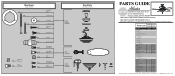
.../Shade Bottom Cap Finial Pull Chain Pendant Pull Chain Pull Chain Dummy Terminal, Male Dummy Terminal, Female Cap, Switch Housing Plug Button Balancing Kit Model # 21315 Asm. Dwg. # 98871-01 Finish Qnty 1 Roman Bronze Part # 96759-86 1 G0655-86 1 88738-01 1 97231-07 2 77646-04 1 97838...97832-02 1 66748-01 1 66747-01 2 74393-08 1 63756-47 2 63756-56 1 08198-01 1 08200-01 1 73853-01 1 73854-01 1 65666-01 Hunter Fan Company • 7130 Goodlett Farms Pkwy. #400 • Memphis, TN 38016 • www.hunterfan.com • 98000-01-936 12-21-2010 • ©...
.../Shade Bottom Cap Finial Pull Chain Pendant Pull Chain Pull Chain Dummy Terminal, Male Dummy Terminal, Female Cap, Switch Housing Plug Button Balancing Kit Model # 21315 Asm. Dwg. # 98871-01 Finish Qnty 1 Roman Bronze Part # 96759-86 1 G0655-86 1 88738-01 1 97231-07 2 77646-04 1 97838...97832-02 1 66748-01 1 66747-01 2 74393-08 1 63756-47 2 63756-56 1 08198-01 1 08200-01 1 73853-01 1 73854-01 1 65666-01 Hunter Fan Company • 7130 Goodlett Farms Pkwy. #400 • Memphis, TN 38016 • www.hunterfan.com • 98000-01-936 12-21-2010 • ©...


