
Owner's Manual
Page 1
... 12. Check Operation of Heating and/or Cooling System 13 If You Have A Problem ...15 Wiring Diagrams...16 ® U.S. CT8775A,C THE DIGITAL ROUND™ NON-PROGRAMMABLE THERMOSTATS CT8775A Heat Only Thermostat (20 to 30 Vac) and CT8775C Heating-Cooling Thermostat (20 to 30 Vac) Para obtener un documento con las instrucciones en español, por favor visite nuestro sitio de web a: www.honeywell.com/yourhome. Wire Wallplate Terminals...8 Step...
... 12. Check Operation of Heating and/or Cooling System 13 If You Have A Problem ...15 Wiring Diagrams...16 ® U.S. CT8775A,C THE DIGITAL ROUND™ NON-PROGRAMMABLE THERMOSTATS CT8775A Heat Only Thermostat (20 to 30 Vac) and CT8775C Heating-Cooling Thermostat (20 to 30 Vac) Para obtener un documento con las instrucciones en español, por favor visite nuestro sitio de web a: www.honeywell.com/yourhome. Wire Wallplate Terminals...8 Step...
Owner's Manual
Page 2
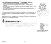
Turn the dial to adjust the temperature setting. • Large easy-to read display. This manual answers many of the questions that contains mercury in a sealed tube, do not place your Honeywell thermostat - Read these instructions can arise as you become familiar and comfortable with your old control in a dark room or hallway. • No batteries required. Contact your local waste management authority...
Turn the dial to adjust the temperature setting. • Large easy-to read display. This manual answers many of the questions that contains mercury in a sealed tube, do not place your Honeywell thermostat - Read these instructions can arise as you become familiar and comfortable with your old control in a dark room or hallway. • No batteries required. Contact your local waste management authority...
Owner's Manual
Page 3
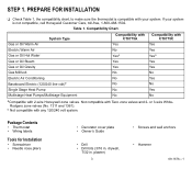
... Honeywell Customer Care, toll-free, 1-800-468-1502. Table 1. drywall, 7/32 in . Compatibility Chart. plaster) 3 • Screws and wall anchors • Hammer 69-1676-1 System Type Gas or Oil Warm Air Electric Warm Air Gas or Oil Hot Water Gas or Oil Steam Gas or Oil Gravity Gas Millivolt Electric Air Conditioning Baseboard Electric (120/240 line volt)b Single Stage Heat Pump Multistage Heat Pumps/Multistage Equipment Compatibility with CT8775A...
... Honeywell Customer Care, toll-free, 1-800-468-1502. Table 1. drywall, 7/32 in . Compatibility Chart. plaster) 3 • Screws and wall anchors • Hammer 69-1676-1 System Type Gas or Oil Warm Air Electric Warm Air Gas or Oil Hot Water Gas or Oil Steam Gas or Oil Gravity Gas Millivolt Electric Air Conditioning Baseboard Electric (120/240 line volt)b Single Stage Heat Pump Multistage Heat Pumps/Multistage Equipment Compatibility with CT8775A...
Owner's Manual
Page 4
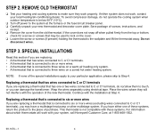
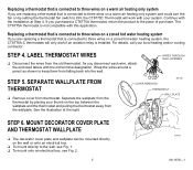
... heating and cooling systems to the place of purchase. Save package of the new thermostat. This thermostat is connected to six or more wires (excluding wires connected to six or more wires If you are replacing a thermostat that may have either system does not work, contact your new thermostat and decorator cover plate. Wrap the wires separately using electrical tape. If you are replacing: • A thermostat that has wires connected to C or C1 terminals. • A thermostat...
... heating and cooling systems to the place of purchase. Save package of the new thermostat. This thermostat is connected to six or more wires (excluding wires connected to six or more wires If you are replacing a thermostat that may have either system does not work, contact your new thermostat and decorator cover plate. Wrap the wires separately using electrical tape. If you are replacing: • A thermostat that has wires connected to C or C1 terminals. • A thermostat...
Owner's Manual
Page 5
... purchased a CT8775A thermostat, return the product to keep them from the thermostat by setting the thermostat fan switch to ON, the CT8775C Thermostat will only work with the installation at the right. Replacing a thermostat that is connected to three wires on a warm air heating only system If you are replacing a thermostat that is connected to three wires on a warm air heating only system and could turn the fan on by placing your thumb on the wall or...
... purchased a CT8775A thermostat, return the product to keep them from the thermostat by setting the thermostat fan switch to ON, the CT8775C Thermostat will only work with the installation at the right. Replacing a thermostat that is connected to three wires on a warm air heating only system If you are replacing a thermostat that is connected to three wires on a warm air heating only system and could turn the fan on by placing your thumb on the wall or...

Owner's Manual
Page 6
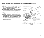
... decorator cover plate against the wall so that the UP indicator on the wallplate is WALL ANCHORS (2) DECORATOR COVER PLATE pointing up . ❑ Use a pencil to wall (heating-cooling wallplate and drill two 3/16 in the wall (if drywall) at the shown). Gently tap the provided anchors into the wall. ❑ If attaching the wallplate directly to the wall, pull the wires through the wiring hole on...
... decorator cover plate against the wall so that the UP indicator on the wallplate is WALL ANCHORS (2) DECORATOR COVER PLATE pointing up . ❑ Use a pencil to wall (heating-cooling wallplate and drill two 3/16 in the wall (if drywall) at the shown). Gently tap the provided anchors into the wall. ❑ If attaching the wallplate directly to the wall, pull the wires through the wiring hole on...
Owner's Manual
Page 7
... onto Electrical Box ❑ Pull the wires through the wiring hole on the decorator cover plate with the electrical box screw holes, and attach the decorator cover plate to the decorator cover plate with two 1/2 in. . screws. screws. ❑ Pull the wires through the wiring hole on the decorator cover plate. ❑ Place the decorator cover plate against the electrical box so that the UP indicator in . Turn the...
... onto Electrical Box ❑ Pull the wires through the wiring hole on the decorator cover plate with the electrical box screw holes, and attach the decorator cover plate to the decorator cover plate with two 1/2 in. . screws. screws. ❑ Pull the wires through the wiring hole on the decorator cover plate. ❑ Place the decorator cover plate against the electrical box so that the UP indicator in . Turn the...
Owner's Manual
Page 8
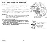
... these terminals. ❑ For wiring diagrams, see illustration). FACTORY INSTALLED JUMPER M19495 FOR STRAIGHT INSERTION STRIP 5/16 IN. (8 MM). M19496 69-1676-1 8 Refer to help prevent drafts from adversely affecting thermostat operation. Tighten the terminals. ❑ Plug the hole in the wall with local codes and ordinances. If unsure about household wiring procedures, call your new thermostat. Slip each wire beneath its matching terminal. IMPORTANT Remove the factory-installed jumper connecting terminals R and...
... these terminals. ❑ For wiring diagrams, see illustration). FACTORY INSTALLED JUMPER M19495 FOR STRAIGHT INSERTION STRIP 5/16 IN. (8 MM). M19496 69-1676-1 8 Refer to help prevent drafts from adversely affecting thermostat operation. Tighten the terminals. ❑ Plug the hole in the wall with local codes and ordinances. If unsure about household wiring procedures, call your new thermostat. Slip each wire beneath its matching terminal. IMPORTANT Remove the factory-installed jumper connecting terminals R and...
Owner's Manual
Page 9
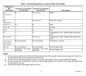
... Terminals Connect To Terminals on CT8775A on Old and New Thermostats. W - - - - Rc (see Note 2) W Y G O B (see Note 3) W2, H2 Y2 Connect to both Rh and R terminals on the old thermostat, remove jumper between R and Rc on the new thermostat, remove jumper between R and Rc. 3. Power for cooling Heat Cooling Fan Changeover in heat. (Single stage heat pump only). Transformer common Do not continue Do not continue Second stage heat. installation. installation. Connect O to O. Tape off wire with electri- cal tape and do not use...
... Terminals Connect To Terminals on CT8775A on Old and New Thermostats. W - - - - Rc (see Note 2) W Y G O B (see Note 3) W2, H2 Y2 Connect to both Rh and R terminals on the old thermostat, remove jumper between R and Rc on the new thermostat, remove jumper between R and Rc. 3. Power for cooling Heat Cooling Fan Changeover in heat. (Single stage heat pump only). Transformer common Do not continue Do not continue Second stage heat. installation. installation. Connect O to O. Tape off wire with electri- cal tape and do not use...
Owner's Manual
Page 10
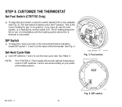
... CT8775A,C Thermostats will provide optimal temperature control if DIP switches 1 and 2 are set according to set the heat cycle rate. DIP switch. 10 The fuel switch is factory set the switch to turn on immediately with the heating system where the G terminal is the correct setting for gas or oil systems. If you have an electric heat system, or a heat pump, set in the F position. See Fig. 4. Set Heat Cycle Rate ❑ Use DIP switches 1 and 2 to your particular heating...
... CT8775A,C Thermostats will provide optimal temperature control if DIP switches 1 and 2 are set according to set the heat cycle rate. DIP switch. 10 The fuel switch is factory set the switch to turn on immediately with the heating system where the G terminal is the correct setting for gas or oil systems. If you have an electric heat system, or a heat pump, set in the F position. See Fig. 4. Set Heat Cycle Rate ❑ Use DIP switches 1 and 2 to your particular heating...
Owner's Manual
Page 11
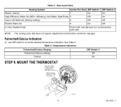
... OF THERMOSTAT AND WALL PLATE. Heat Cycle Rate. Temperature Indication. PRESS UPPER EDGE OF CASE TO LATCH M19498 11 69-1676-1 NOTE: The cooling cycle rate does not require adjustment and therefore cannot be changed. Fahrenheit/Celsius Display Fahrenheit (factory setting) Celsius DIP Switch 3 Off On STEP 9. Heating System Cycles Per Hour DIP Switch 1 DIP Switch 2 Steam, Gravity 1 High Efficiency Warm Air (90%+ efficiency), Hot Water, Heat Pump 3 On On Off On Gas or Oil Warm Air (factory setting) Electric Warm Air...
... OF THERMOSTAT AND WALL PLATE. Heat Cycle Rate. Temperature Indication. PRESS UPPER EDGE OF CASE TO LATCH M19498 11 69-1676-1 NOTE: The cooling cycle rate does not require adjustment and therefore cannot be changed. Fahrenheit/Celsius Display Fahrenheit (factory setting) Celsius DIP Switch 3 Off On STEP 9. Heating System Cycles Per Hour DIP Switch 1 DIP Switch 2 Steam, Gravity 1 High Efficiency Warm Air (90%+ efficiency), Hot Water, Heat Pump 3 On On Off On Gas or Oil Warm Air (factory setting) Electric Warm Air...
Owner's Manual
Page 12
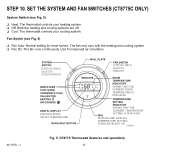
... heating and cooling systems are off. ❑ Cool: The thermostat controls your cooling system. Use for most homes. STEP 10. SET THE SYSTEM AND FAN SWITCHES (CT8775C ONLY) System Switch (see Fig. 5) ❑ Fan Auto: Normal setting for improved air circulation. 69-1676-1 (CT8775C ONLY) SELECTS COOL/OFF/HEAT (CT8775C ONLY) SELECTS ON/AUTO ROOM SET SHOWS THAT THE CURRENT ROOM TEMPERATURE IS DISPLAYED DISPLAYS ROOM OR SET TEMPERATURE SHOWS THAT THE CURRENT TEMPERATURE SETTING IS DISPLAYED DISPLAYS AND ADJUSTS TEMPERATURE SETTING/ TURNS BACKLIGHT...
... heating and cooling systems are off. ❑ Cool: The thermostat controls your cooling system. Use for most homes. STEP 10. SET THE SYSTEM AND FAN SWITCHES (CT8775C ONLY) System Switch (see Fig. 5) ❑ Fan Auto: Normal setting for improved air circulation. 69-1676-1 (CT8775C ONLY) SELECTS COOL/OFF/HEAT (CT8775C ONLY) SELECTS ON/AUTO ROOM SET SHOWS THAT THE CURRENT ROOM TEMPERATURE IS DISPLAYED DISPLAYS ROOM OR SET TEMPERATURE SHOWS THAT THE CURRENT TEMPERATURE SETTING IS DISPLAYED DISPLAYS AND ADJUSTS TEMPERATURE SETTING/ TURNS BACKLIGHT...
Owner's Manual
Page 13
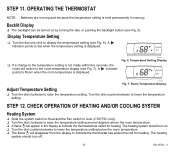
... OPERATION OF HEATING AND/OR COOLING SYSTEM Heating System ❑ Slide the system switch to Heat and the Fan switch to Auto (CT8775C only). ❑ Turn the dial clockwise to raise the temperature setting several degrees above the room temperature. ❑ A flame will switch to display the temperature setting (see Fig. 5). Adjust Temperature Setting ❑ Turn the dial clockwise to Set when the temperature setting is displayed. Room Temperature Display. STEP 12. ROOM SET M19490 Fig. 7. OPERATING THE THERMOSTAT NOTE: Batteries...
... OPERATION OF HEATING AND/OR COOLING SYSTEM Heating System ❑ Slide the system switch to Heat and the Fan switch to Auto (CT8775C only). ❑ Turn the dial clockwise to raise the temperature setting several degrees above the room temperature. ❑ A flame will switch to display the temperature setting (see Fig. 5). Adjust Temperature Setting ❑ Turn the dial clockwise to Set when the temperature setting is displayed. Room Temperature Display. STEP 12. ROOM SET M19490 Fig. 7. OPERATING THE THERMOSTAT NOTE: Batteries...
Owner's Manual
Page 14
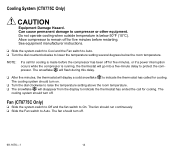
... snowflake will flash during this delay. ❑ After five minutes, the thermostat will go into a five-minute delay to Auto. The cooling system should run continuously. ❑ Slide the Fan switch to protect the compressor. The fan should turn off . 69-1676-1 14 See equipment manufacturer instructions. ❑ Slide the system switch to Cool and the Fan switch to Auto. ❑ Turn the dial counterclockwise to indicate the thermostat has...
... snowflake will flash during this delay. ❑ After five minutes, the thermostat will go into a five-minute delay to Auto. The cooling system should run continuously. ❑ Slide the Fan switch to protect the compressor. The fan should turn off . 69-1676-1 14 See equipment manufacturer instructions. ❑ Slide the system switch to Cool and the Fan switch to Auto. ❑ Turn the dial counterclockwise to indicate the thermostat has...
Owner's Manual
Page 15
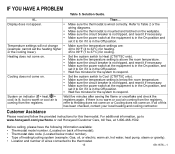
... information available: • Thermostat model number. (Located on indicator ( = heat, = cool) is lit, but no warm or cool air coming from the registers, refer to 32°C) for heating. If all of heating/cooling system (example: Gas, oil, or electric; IF YOU HAVE A PROBLEM Table 5. If... Refer to Table 2 or the wiring diagrams. • Make sure the thermostat is mounted and latched on . Cooling does not come on the wallplate...
... information available: • Thermostat model number. (Located on indicator ( = heat, = cool) is lit, but no warm or cool air coming from the registers, refer to 32°C) for heating. If all of heating/cooling system (example: Gas, oil, or electric; IF YOU HAVE A PROBLEM Table 5. If... Refer to Table 2 or the wiring diagrams. • Make sure the thermostat is mounted and latched on . Cooling does not come on the wallplate...
Owner's Manual
Page 16
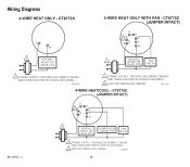
M19452 16 Wiring Diagrams R W 1 HEATING RELAY OR VALVE COIL 1 POWER SUPPLY. M19451 69-1676-1 O B 2 Rc G R Y W 1 HEATING COMPRESSOR FAN RELAY OR VALVE COIL CONTACTOR RELAY 1 POWER SUPPLY. PROVIDE DISCONNECT MEANS AND OVERLOAD PROTECTION AS REQUIRED. PROVIDE DISCONNECT MEANS AND OVERLOAD PROTECTION AS REQUIRED. 2 FACTORY INSTALLED JUMPER. PROVIDE DISCONNECT MEANS AND OVERLOAD PROTECTION AS REQUIRED. 2 FACTORY INSTALLED JUMPER. M19450 O B Rc 2 G R Y W 1 HEATING RELAY OR VALVE COIL FAN RELAY 1 POWER SUPPLY.
M19452 16 Wiring Diagrams R W 1 HEATING RELAY OR VALVE COIL 1 POWER SUPPLY. M19451 69-1676-1 O B 2 Rc G R Y W 1 HEATING COMPRESSOR FAN RELAY OR VALVE COIL CONTACTOR RELAY 1 POWER SUPPLY. PROVIDE DISCONNECT MEANS AND OVERLOAD PROTECTION AS REQUIRED. PROVIDE DISCONNECT MEANS AND OVERLOAD PROTECTION AS REQUIRED. 2 FACTORY INSTALLED JUMPER. PROVIDE DISCONNECT MEANS AND OVERLOAD PROTECTION AS REQUIRED. 2 FACTORY INSTALLED JUMPER. M19450 O B Rc 2 G R Y W 1 HEATING RELAY OR VALVE COIL FAN RELAY 1 POWER SUPPLY.
Owner's Manual
Page 17
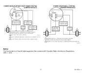
... 2 G R Y W COMPRESSOR CONTACTOR HEATING 1 RELAY OR VALVE COIL FAN RELAY 1 1 POWER SUPPLY. M19454 Notice: This thermostat is a Class B digital apparatus that complies with Canadian Radio Interference Regulations, CRC c. 1374. 17 69-1676-1 4 O Rc 2 R B G Y3 W COMPRESSOR CONTACTOR HEAT CHANGEOVER VALVE 1 FAN COOL RELAY CHANGEOVER VALVE 1 POWER SUPPLY. M19453 3 USE A JUMPER WIRE (NOT SUPPLIED) TO CONNECT W TO Y. 4 USE EITHER O OR B FOR HEAT PUMP CHANGEOVER. PROVIDE DISCONNECT MEANS AND OVERLOAD PROTECTION AS REQUIRED. 2 REMOVE FACTORY INSTALLED JUMPER...
... 2 G R Y W COMPRESSOR CONTACTOR HEATING 1 RELAY OR VALVE COIL FAN RELAY 1 1 POWER SUPPLY. M19454 Notice: This thermostat is a Class B digital apparatus that complies with Canadian Radio Interference Regulations, CRC c. 1374. 17 69-1676-1 4 O Rc 2 R B G Y3 W COMPRESSOR CONTACTOR HEAT CHANGEOVER VALVE 1 FAN COOL RELAY CHANGEOVER VALVE 1 POWER SUPPLY. M19453 3 USE A JUMPER WIRE (NOT SUPPLIED) TO CONNECT W TO Y. 4 USE EITHER O OR B FOR HEAT PUMP CHANGEOVER. PROVIDE DISCONNECT MEANS AND OVERLOAD PROTECTION AS REQUIRED. 2 REMOVE FACTORY INSTALLED JUMPER...
Owner's Manual
Page 18
... 4Z9 This warranty does not cover removal or reinstallation costs. HONEYWELL SHALL NOT BE LIABLE FOR ANY LOSS OR DAMAGE OF ANY KIND, INCLUDING ANY INCIDENTAL OR CONSEQUENTIAL DAMAGES RESULTING, DIRECTLY OR INDIRECTLY FROM ANY BREACH OF ANY WARRANTY, EXPRESS OR IMPLIED, OR ANY OTHER FAILURE OF THIS PRODUCT. Honeywells sole responsibility shall be free from the date of...
... 4Z9 This warranty does not cover removal or reinstallation costs. HONEYWELL SHALL NOT BE LIABLE FOR ANY LOSS OR DAMAGE OF ANY KIND, INCLUDING ANY INCIDENTAL OR CONSEQUENTIAL DAMAGES RESULTING, DIRECTLY OR INDIRECTLY FROM ANY BREACH OF ANY WARRANTY, EXPRESS OR IMPLIED, OR ANY OTHER FAILURE OF THIS PRODUCT. Honeywells sole responsibility shall be free from the date of...
Owner's Manual
Page 20
Honeywell Limited-Honeywell Limitée 1985 Douglas Drive North 35 Dynamic Drive Golden Valley, MN 55422 Scarborough, Ontario M1V 4Z9 69-1676-1 J.S. Rev. 6-04 www.honeywell.com/yourhome Automation and Control Solutions Honeywell International Inc.
Honeywell Limited-Honeywell Limitée 1985 Douglas Drive North 35 Dynamic Drive Golden Valley, MN 55422 Scarborough, Ontario M1V 4Z9 69-1676-1 J.S. Rev. 6-04 www.honeywell.com/yourhome Automation and Control Solutions Honeywell International Inc.


